manuals.online logo
Brands
  1. Home
  2. •
  3. Brands
  4. •
  5. ABB
  6. •
  7. Lighting Equipment
  8. •
  9. ABB Stanilite User manual

ABB Stanilite User manual

—
INSTALLATION MANUAL
Stanilite®
Platinum exit LED edgelit surface mount
DALI emergency
Doc no. 29-01166_1
This document covers What’s inside the box
Safety warning Surface mount base
assembly
Installation instructions Diffuser assembly
Removal instructions Surface mount base cover
Testing precautions Pictograph insert pack
Troubleshooting guide Installation manual
Warranty information
Troubleshooting guide
If you have installed and connected the fitting as per the instructions listed earlier and it does
not function correctly, use the following table as a guide to fixing the problem. Look up the
type of fault in the left column and check the possible causes from the right column.
If the fitting still does not work after checking these possible causes, contact ABB customer
service in Australia on 1800 60 20 20.
—
ABB Australia Pty Limited
For enquiries
ABB contact centre: 1800 60 20 20
E-mail: AU-ABB-Stanilite@abb.com
www.stanilite.com.au © Copyright 2020 ABB. All rights reserved.
9AKK107046A0981 - A - Feb 2020
No. Fault Possible causes
LED lamp and indicator LED not lit AC supply not connected; or
AC supply turned off
LED lamp not lit but red indicator is lit LED lamp damaged; or
LED lamp plug incorrectly inserted in the mother board
LED lamp not lit but indicator LED is flashing green LED lamp damaged; or
LED lamp plug incorrectly inserted in the mother board
LED lamp is lit but red indicator LED not lit LED damaged; or
Check battery connection
The LED lamp does not switch to emergency mode
when the test button is pressed
Test switch damaged
Indicator LED is constant green Test switch damaged; or
Self check fail - return to factory
Indicator LED not red after commissioning Check battery connection and battery plug polarity
The LED lamp works momentarily on emergency
when the test button is pressed

Thank you for choosing ABB product
Please read this document thoroughly before
commencing installation and retain for future
reference. Contact ABB customer service in
Australia on 1800 60 20 20 if you need any
assistance. The installation instructions were
correct at the time of print. To reflect changes in
technology and Australian standards; ABB
reserves the right to amend the instructions
without notice. Updated document can be found
on the Stanilite website.
Safety warning
In Australia and New Zealand, only licensed
electricians are permitted by law to work with
240 volt electrical installations.
Do not attempt to install or connect this product
unless you are a licensed electrician.
Turn off and isolate the electrical supply before
connecting this fitting to the building wires.
Do not touch the terminals of the terminal block
when the light fitting is energised.
The only user-serviceable part is the battery
pack. LED light source is not user-serviceable.
Do not attempt to service other parts of the
fitting as this will void the warranty.
As the installer, it is your responsibility to ensure
compliance with all relevant building and safety

the applicable standards for data and mains
cabling installation procedures and
requirements.
DALI (Digital Addressable Lighting Interface)
DALI is widely acknowledged as being an open
protocol as defined under IEC 62386 and is
designed only for communication in lighting
systems.
ABB exit and emergency luminaire with DALI
functionality comply with DALI standard IEC
62386.
The DALI edgelit surface mount wiring consists
of additional 2 way terminal block in the base
labelled as + and - for DALI control wires apart
from the mains terminals, ie: USA, N and E.
Note: No mains or mains carrying cables are to
be connected to DALI terminals or 2 control
wires (white and black).
Important to note:
• This product is designed for indoor use only.
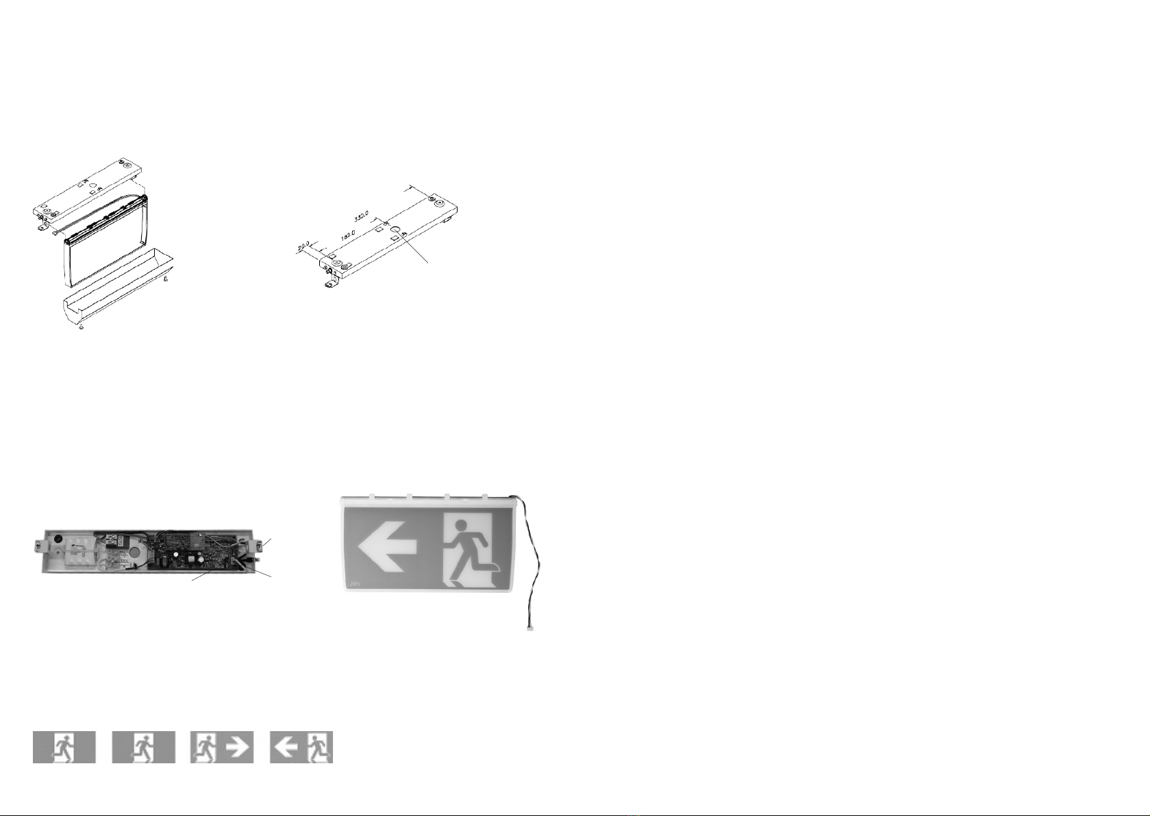
Figure 1a: Showing sequence of components
Note: Cable entry
hole is 24mm offset
from the centre of
the fitting
Figure 3: Pictograph inserts
Figure 2: Connect wire loom plug to the mother board
Figure 1b: Mounting and cable entry hole dimensions
Diffuser
holding
latch
White
wires
Mother board
Installation instructions
Note: The circuit supplying mains power to the fitting must not be energised until installation of
the fitting is completed.
1. 
hole dimensions shown in figure 1b can be used as a template, for the purpose of marking/drilling.
Once the base is installed on the ceiling, connect the incoming unswitched active, neutral and earth
to terminal marked USA, N and E respectively. Connect the DALI control wires to the DALI terminal
block.
Removal instructions
1. To remove/uninstall fitting from the ceiling,
the steps to be followed are the reversal of
installation process. Turn off mains power to
fitting, the fitting will automatically switch
onto emergency mode as the mains power
has been turned off. It will stay on in the
emergency mode until such time as the
battery cut-off threshold is reached.
2. Remove cover by undoing the 2 cover screws
turning anti-clockwise one by one using
suitable screwdriver, make sure to hold cover
with one hand while undoing the last screw.
Once the screws are undone, remove the cover
gently. The next step is to remove the diffuser
assembly.
3. To remove diffuser assembly, hold the diffuser
holding latch with thumb and fingers on one
end and push gently to the opposite end to
remove diffuser from the holding latch. Once
diffuser is removed from the latch, disconnect/
remove wire loom plug from the mother board.
Once the diffuser assembly is removed,
disconnect the battery pack plug on the
mother board. The next step is to remove base
of the installed fitting.
4. Undo the mains wire connections ie:
unswitched active, neutral and earth cable (and

terminal block using a suitably sized
screwdriver. Unscrew the mounting screws
turning anti-clockwise one by one using
suitable screwdriver, and make sure to hold
base with one hand while undoing the last
screw. Once the mounting screws are undone,
the base can be pulled down gently from the
ceiling.
5. When the fitting is reconnected to the mains
supply, it will need time to recharge its battery
before it will be capable of a full length
discharge again. The ability of the fitting to
operate on emergency is determined by the
age, charge level, operating temperature
conditions and environmental circumstances
of the battery in the fitting.
2. Once the base is secured to the ceiling, hold the diffuser assembly in your hand and connect the

should be towards the centre of the fitting. Once the plug is connected, lay the wire loom carefully

then push up the other side of the diffuser, the diffuser clicks and locks in place. Once the diffuser is
locked in place, the cover is easily fixed to the base via 2 screws. Hold the cover in your hand and bring
up to the base, pass diffuser through the cut out; make sure the side rectangular cut out on the cover
for the LED and test switch lines up with LED and test switch on the base. Once the holes on both
sides of the base and cover line up, secure with the screws provided.
3. Install the pictograph inserts by sliding into the diffuser. The pictograph inserts can be installed in
the diffuser prior to installing the diffuser assembly in the fitting. Fitting is supplied standard with all
pictograph insert options for single and double sided, as a complete one box solution to meet any
site/project needs.
4. The circuit supplying mains power to the fitting can now be energised.
5. Check the operation of the fitting to ensure that the installation was successful. When powered up,
allow a few minutes to give the battery a small charge, then press the manual test button located on
the fitting. Hold the test button in for a few seconds and observe the operation of the lamp switching
from mains to the emergency mode. If the lamp on emergency mode works momentarily, that’s okay.
Try again in a few more minutes because if the battery was completely discharged, it may take a little
time to charge up enough to operate even momentarily. After this time, press the test button again
and if the lamp does not work at all, check the supply, the connections and the troubleshooting guide
at the end of this document.
Important: 24 hours is required to allow the fitting battery to reach full capacity, ie: prior to a
discharge test. As the installer, it is your responsibility to conduct the initial discharge testing of
the installed fitting. Refer to AS/NZS 2293.
Construction sites
Continuously switching off the mains power
supply that is connected to emergency light
fittings during the construction phase of an
installation will cause these fittings to discharge
and charge their batteries many times over a
short period; this can shorten life of the battery.
ABB does not recommend such practices and
may not honour the warranty on batteries when
they are subjected to such harsh operating
conditions. Emergency light fittings are designed
to be discharge tested once every 6 months as
per AS/NZS 2293.2, subjecting the product to
repeated discharge or charge cycles is regarded
as an abuse of the fittings.
Testing precautions
Once the fitting is permanently connected to the
mains supply, a commissioning discharge test as
required in AS/NZS 2293.2 must be carried out.
You will need to allow 24 hours for the battery to
fully charge prior to conducting this test,

requires that fittings operate in emergency mode
for a period not less than 2 hours for their
commissioning test and for not less than 90
minutes thereafter (it is required that 6 monthly

keep the records for the commissioning test and
enter them into the building emergency services
logbook or via other recording methods as
allowed by AS/NZS 2293.2.

Other ABB Lighting Equipment manuals

ABB Stanilite Spitfire Standard User manual

ABB

ABB Stanilite Spitfire Standard User manual

ABB Thomas&Betts Standard User manual

ABB

ABB Thomas&Betts Standard User manual

ABB EGNL Series User manual

ABB

ABB EGNL Series User manual

ABB Stanilite Standard User manual

ABB

ABB Stanilite Standard User manual

ABB EMERGI-LITE Serenga Manual

ABB

ABB EMERGI-LITE Serenga Manual

ABB Stanilite Emergency User manual

ABB

ABB Stanilite Emergency User manual

ABB GE ReliaGear Lighting Panelboard User manual

ABB

ABB GE ReliaGear Lighting Panelboard User manual

ABB Stanilite Nexus RF User manual

ABB

ABB Stanilite Nexus RF User manual

ABB PrimEvo SM100E Manual

ABB

ABB PrimEvo SM100E Manual

ABB Stanilite Quickfit Nexus LX User manual

ABB

ABB Stanilite Quickfit Nexus LX User manual

ABB PrimEvo TW220E Manual

ABB

ABB PrimEvo TW220E Manual

ABB Stanilite Standard User manual

ABB

ABB Stanilite Standard User manual

ABB EMERGI-LITE Guideway Manual

ABB

ABB EMERGI-LITE Guideway Manual

ABB Thomas & Betts Standard User manual

ABB

ABB Thomas & Betts Standard User manual

ABB Stanilite Spitfire Standard User manual

ABB

ABB Stanilite Spitfire Standard User manual

ABB Stanilite Spitfire Standard User manual

ABB

ABB Stanilite Spitfire Standard User manual

ABB Emergi-Lite Serenga Sun-Lite Manual

ABB

ABB Emergi-Lite Serenga Sun-Lite Manual

ABB KAUFEL Lutia Manual

ABB

ABB KAUFEL Lutia Manual

ABB EMERGI-LITE Guideway Manual

ABB

ABB EMERGI-LITE Guideway Manual

ABB Thomas & Betts Standard User manual

ABB

ABB Thomas & Betts Standard User manual

ABB Stanilite Quickfit Standard User manual

ABB

ABB Stanilite Quickfit Standard User manual

ABB Stanilite Economy e-Luna circular LED User manual

ABB

ABB Stanilite Economy e-Luna circular LED User manual

Popular Lighting Equipment manuals by other brands

Norsup NORSUPONE Original manual

Norsup

Norsup NORSUPONE Original manual

RZB Lighting GSUN-S Instruction

RZB Lighting

RZB Lighting GSUN-S Instruction

Monster MLB7-1030 Operation manual

Monster

Monster MLB7-1030 Operation manual

Blue Square Q360 Homeowner's manual

Blue Square

Blue Square Q360 Homeowner's manual

Unilamp FUJI Round installation manual

Unilamp

Unilamp FUJI Round installation manual

ETC Source 4WRD Installation and user manual

ETC

ETC Source 4WRD Installation and user manual

XanLite BL200RUSB manual

XanLite

XanLite BL200RUSB manual

Feniex FUSION-S 400 manual

Feniex

Feniex FUSION-S 400 manual

Cree C-LITE C-WP-A-FCT3 Series installation instructions

Cree

Cree C-LITE C-WP-A-FCT3 Series installation instructions

RUTEC VARDAFLEX Select Ultra quick start guide

RUTEC

RUTEC VARDAFLEX Select Ultra quick start guide

Heitronic 47211 Installation and operating instructions

Heitronic

Heitronic 47211 Installation and operating instructions

RUTEC VARDAflex COB R-to-R Plus Instructions for use

RUTEC

RUTEC VARDAflex COB R-to-R Plus Instructions for use

Retlux RLS 103 operating manual

Retlux

Retlux RLS 103 operating manual

Wheelock CH90-24MCCH Series installation instructions

Wheelock

Wheelock CH90-24MCCH Series installation instructions

ETC Irideon AR50 user guide

ETC

ETC Irideon AR50 user guide

Martin FiberSource QFX 150 user manual

Martin

Martin FiberSource QFX 150 user manual

JB Systems ACCU MINI-PAR 12TC MK2 Operation manual

JB Systems

JB Systems ACCU MINI-PAR 12TC MK2 Operation manual

Chauvet Colorado 1-Quad Tour user manual

Chauvet

Chauvet Colorado 1-Quad Tour user manual

manuals.online logo
manuals.online logoBrands
  • About & Mission
  • Contact us
  • Privacy Policy
  • Terms and Conditions

Copyright 2025 Manuals.Online. All Rights Reserved.