Complete Solutions in Emergency Lighting STANILITEComplete Solutions in Emergency Lighting STANILITE
© Thomas & Betts (Australasia) Pty. Ltd. 2016 Rev: 2.0 24 February 2016 3© Thomas & Betts (Australasia) Pty. Ltd. 2016 Rev: 2.0 24 February 2016 2
INSTALLATION INSTRUCTIONS
Important Note: A M6 torx screw driver or drive bit is required for the installation.
1. Remove the unit from the packaging and inspect it for damage or imperfections. If any damage is found, do not install the unit and
notify the Thomas & Betts Product Support Hotline in Australia on 1300 666 595.
2. If all looks okay, proceed with the installation. Put the main frame upside down, remove six (6) special G6 x 1/2 counter sunk Torx
screws by using a Torx pin driver or screw driver. Gently insert a small at head screwdriver into the side of the front cover to lever
it out, remove the front cover. See Figure 3.
3. Loosen the thumb screws to remove the side diffusers. Leave the bottom diffuser on.
4. Remove the Quickt unit from the bracket by gently inserting a small screwdriver into the slot (at ‘D’ in Figure 4) on the front of the
bracket towards the right hand end of the tting to ease the locking tab into the tting and away from the bracket. The unit is then
free to slide to the right along the bracket for about 50mm, at which time the slots line up and it can be lowered away from the
bracket, allowing the two to separate.
Note: The main metal frame can be mounted on either side but inside can only be accessed from one end. Make sure to leave
a gap of at least 650mm to remove the Quickt unit from the metal frame.
5. Determine the mounting conguration and position, ie: Ceiling or Wall. Drill mounting holes at the positions as shown in Figure 1 or
Figure 2. All drilling locations are indicated on the metal frame by dimple features. Due to the wide variety of building construction
materials, mounting screws are not provided with the unit. Use appropriate hardware to suit the individual installation and structural
support needs of the unit (17kg approx). The cable entry hole for Wall mounting can be drilled through the polycarbonate panel
and the cable entry hole for ceiling mount must be drilled at the dimple at the centre of the top face, marked A as shown in
Figure 1.
6. Run the cables in the ceiling or wall space as appropriate through the cable hole into the bracket, a suitable bush may have to be
used to protect the cable as it passes through the cable entry hole into the mounting bracket. Secure the main frame to the wall
or ceiling before terminating any wiring. Strip, connect and terminate the cables as indicated in Figure 3. Ensure that the double
insulation of the cable/s passes completely into the terminal block enclosure so that no single insulation is exposed when the cover
is in place. Be careful with multi-strand conductors that all of the strands are twisted together before insertion into the terminal.
Any stray strands that inadvertently come into contact with their neighbouring terminal or the metal frame of the tting will cause
undesirable results when the tting is powered. Install the plastic panel over the terminal block.
Figure 3: Mains connection & how to get access to main frame
• Maintained ttings are design for permanent illumination: Connect incoming unswitched active, neutral and earth to terminal
marked USA, N and E respectively.
• Data connection for Nexus LX product installation:
The same colour wire from each data cables connects to the terminal marked +.
The other colour wire from each of the data cables connects to the terminal marked -.
When connected, replace the terminal block cover so that it clicks and locks into place.
• No mains or mains carrying cables are to be connected to the data terminals or cables.
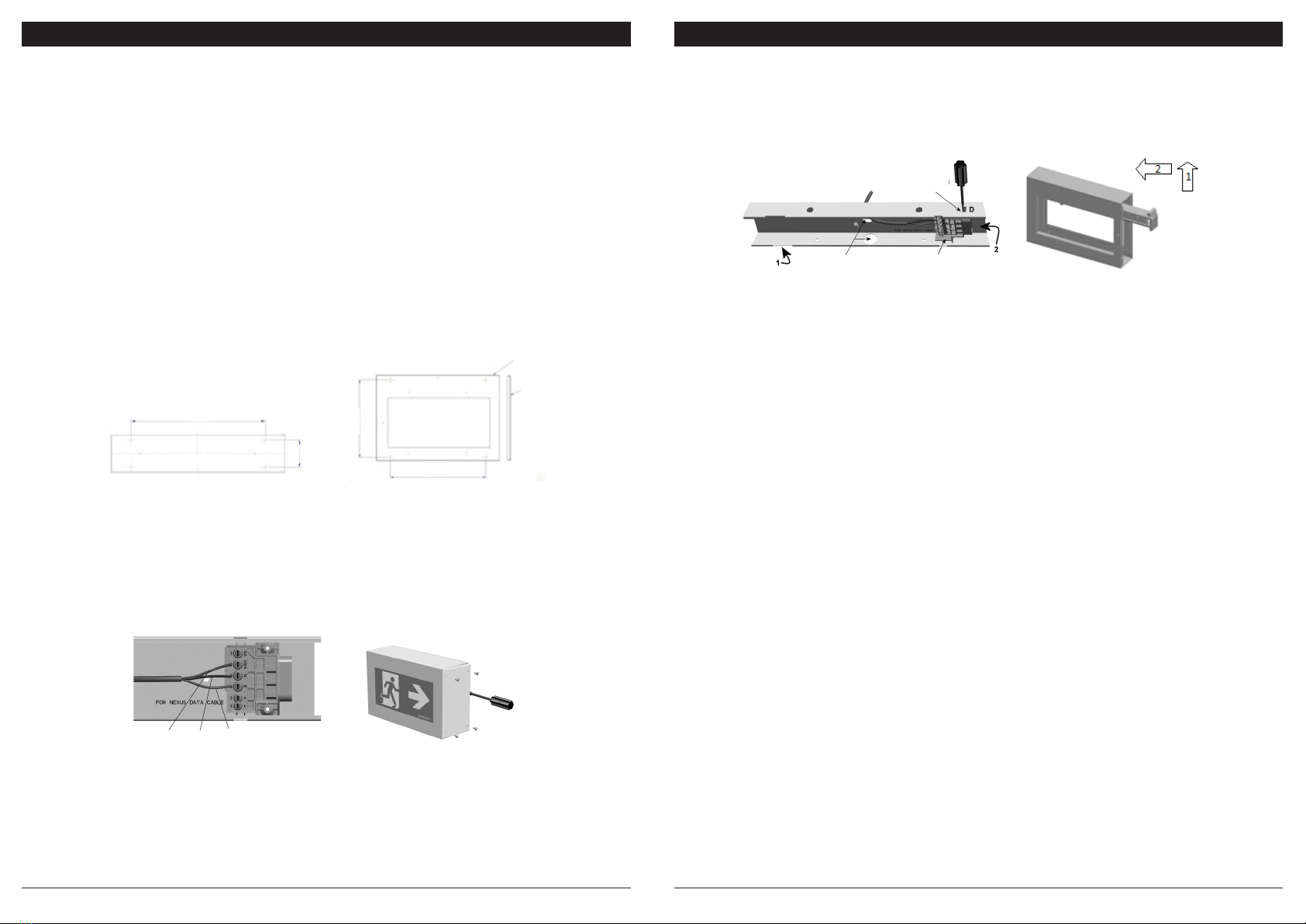
7. Fit the LED lamp (carefully follow the instruction label on top of the Quickt unit) and attach the Quickt unit to the mounting bracket
by aligning the top left hand end of the unit (the end without the protruding electrical connecting metal lugs) with the large cut-away
slot towards the left hand end of the bracket. Slip the left hand end of the unit up into the slot in the left hand end of the bracket
(Step (1) in Figure 4) and hold the unit horizontal to and parallel with the bracket. It should be approximately 50mm to the right of
its nal destination. Simply slide the unit (Step (2) in Figure 4) 50mm to the left along and into the bracket to engage the connection
and the locking tab. Once in place, the unit cannot be removed from the bracket without the use of a tool (a small screwdriver) to
push in the locking tab at ‘D’ in Figure 4.
Figure 4: Quickt Frame Insertion Diagram
8. Once powered up, the LED lamp should energise and remain lit until the power supply fails. The emergency function of the
light tting should only operate when the normal lighting power supply fails or when somebody presses the manual test button
located on the side of the unit. Normal status of the unit when powered, red LED indicates that the power is connected and the
battery is charging or when commissioned on the Nexus LX/RF network and the unit is receiving a command from the Nexus LX/
RF controller to switch into emergency mode. Normal initial uncommissioned status of the indicating LED on the unit is ashing
green. Once commissioned, the LED changes to a steady red and ashes red during test. Please refer to the Nexus LX/RF User
& Technical Guide for a full detailed description of all possible LED states and their meanings.
9. Check operation of the unit to ensure that the installation was successful. When powered up, allow a few minutes to give the battery
a small charge, then press the manual test button located at the top right hand side edge of the unit. Hold the test button in for a
few seconds and observe the operation of the lamp switching from mains to the emergency mode. If the lamp on emergency mode
works momentarily, that’s okay. Try again in a few more minutes because if the battery was completely discharged, it may take a
little time to charge up enough to operate even momentarily. After this time, press the test button again and if the lamp doesn’t work
at all, check the supply, the connections and the trouble shooting guide at the end of this document.
10. If the function test is successful, insert the side diffusers and tighten the thumbscrews by hand (clear polycarbonate panel must
be facing outside). Check and adjust the gasket on the end cover, make sure it is sitting ush on the edge. Fit the end cover to the
enclosure and secure it in place by six M6 Torx screws. For wall mount version you may not need screws on the that side.
REMOVAL INSTRUCTIONS
See steps 3 and 4 in the installation instruction.
TESTING PRECAUTIONS
Once the tting is permanently connected to the mains supply, a commissioning discharge test as required in AS/NZS2293.2 must be
carried out. You will need to allow 24 hours for the battery to fully charge prior to conducting this test, presently (at the time of writing),
the standard requires that ttings operate in emergency mode for a period not less than 2 hours for their commissioning test and for
not less than 90 minutes thereafter (it is required that 6 monthly discharge tests be carried out). You will need to keep the records for
the commissioning test and enter them into the building emergency services logbook or via other recording methods as allowed by
AS/NZ2293.2.
CONSTRUCTION SITES
Continuously switching of the mains power supply that is connected to emergency light ttings during the construction phase of an
installation will cause these ttings to discharge and charge their batteries many times over a short period; this can shorten the life of the
battery and will also result in shortened emergency lamp life for uorescent ttings. Thomas & Betts does not recommend such practices
and may not honour the warranty on batteries when they are subjected to such harsh operating conditions. Emergency light ttings are
designed to be discharge tested once every 6 months as per AS/NZS2293.2, subjecting the product to repeated discharge or charge
cycles is regarded as an abuse of the ttings.
Insert here
to remove
Cable Entry
Holes
Terminal
Block
Neutral Earth
Active
Side
A
100
500
407
500
Figure 1: Ceiling Mount Figure 2: Wall Mount
Top


