ABB i-bus KNX IPS/S 3.5.1 User manual

—
PRODUCT MANUAL
ABB i-bus®KNX
IPS/S 3.5.1
IP Interface Secure


ABB i-bus®KNX
Contents
IPS/S 3.5.1 | 9AKK107680A8655 EN Rev. A i
Contents
Page
1General ................................................................................................. 5
1.1 Using the product manual............................................................................................................ 5
1.1.1 Notes ........................................................................................................................................... 5
1.2 Cyber security (network security) ................................................................................................ 6
1.3 Preventing access to the different media..................................................................................... 6
1.4 Twisted pair cabling..................................................................................................................... 6
1.5 IP cabling inside the building ....................................................................................................... 6
1.6 Connection to the Internet ........................................................................................................... 7
1.7 KNXnet/IP Security...................................................................................................................... 7
1.8 Overview of product and functions .............................................................................................. 8
1.8.1 Overview of versions ................................................................................................................... 9
2Device technology ............................................................................. 11
2.1 Technical data ............................................................................................................................11
2.2 Connection diagram ...................................................................................................................13
2.3 Dimension drawing .....................................................................................................................14
2.4 Mounting and installation............................................................................................................15
2.4.1 Prerequisites for commissioning.................................................................................................15
2.4.2 Supplied state.............................................................................................................................15
2.4.3 Assignment of the physical address ...........................................................................................16
2.4.4 Download reaction......................................................................................................................16
2.4.5 Unloading the device and resetting to factory settings ...............................................................16
2.4.6 Cleaning .....................................................................................................................................17
2.4.7 Maintenance ...............................................................................................................................17
2.5 Description of inputs and outputs ...............................................................................................17
2.6 Operating controls ......................................................................................................................18
2.7 Display elements ........................................................................................................................18
3Commissioning.................................................................................. 19
3.1 Overview.....................................................................................................................................19
3.2 Parameters .................................................................................................................................19
3.3 Group objects .............................................................................................................................21
3.4 Use of the integrated tunneling servers......................................................................................22
3.4.1 Tunneling server settings............................................................................................................23
3.5 KNX Secure................................................................................................................................24
4Planning and application .................................................................. 25
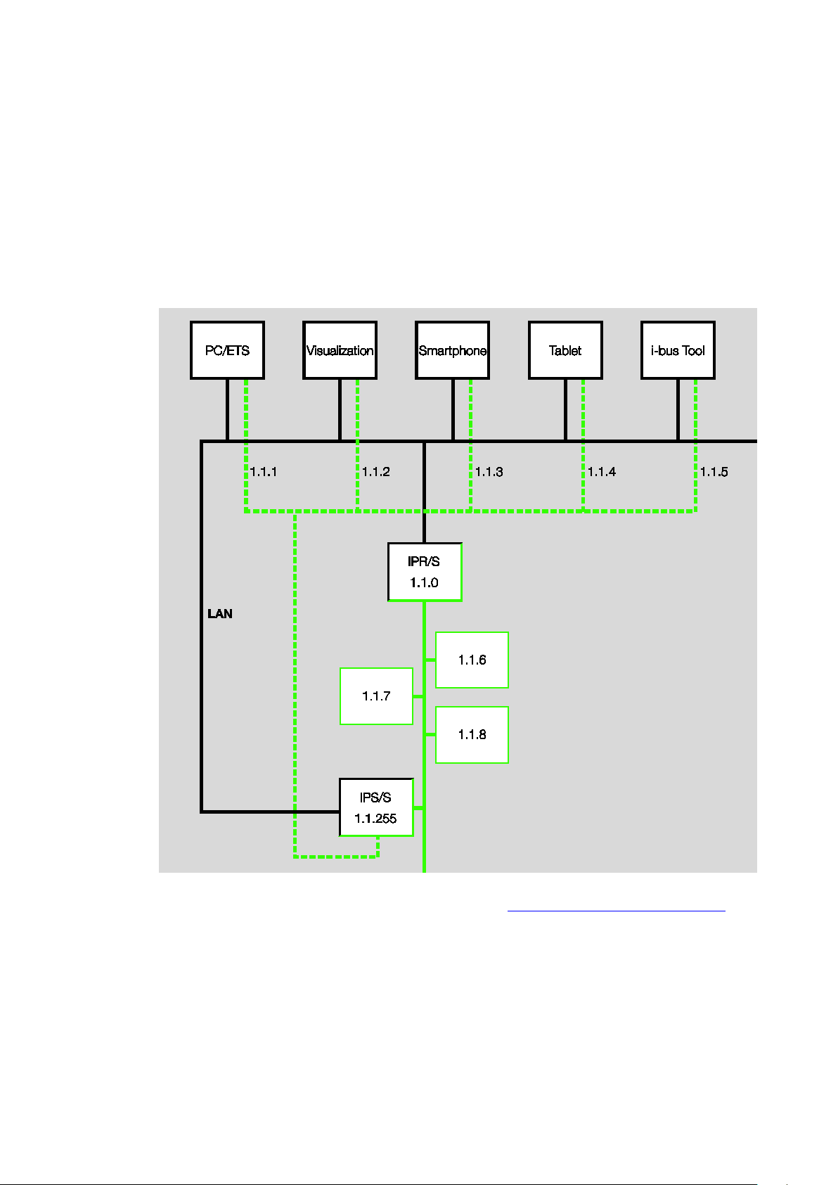
4.1 The IP Interface Secure in the network ......................................................................................25
4.1.1 Assignment of IP address...........................................................................................................25
4.1.2 Monitoring an IPS/S 3.5.1...........................................................................................................25
4.2 The i-bus®Tool...........................................................................................................................26
4.2.1 Discovery....................................................................................................................................26
4.2.2 Firmware update.........................................................................................................................27
AAppendix ............................................................................................ 29
A.1 Ordering details ..........................................................................................................................29
A.2 Open source software components ............................................................................................29


ABB i-bus®KNX
General
IPS/S 3.5.1 | 9AKK107680A8655 EN Rev. A 5
1 General
The ABB i-bus®IP Interface Secure IPS/S 3.5.1 connects the KNX bus to an Ethernet network.
KNX telegrams can be sent to or received from other devices via the network.
The device supports the KNX Secure protocol (KNXnet/IP Security).
1.1 Using the product manual
This manual provides detailed technical information on the function, installation and programming of the
ABB i-bus®KNX device. Explanations on how to use it are accompanied by examples.
This manual is divided into the following chapters:
Chapter 1 General
Chapter 2 Device technology
Chapter 3 Commissioning
Chapter 4 Planning and application
Chapter A Appendix
1.1.1 Notes
Notes and safety instructions are represented as follows in this manual:
Note
Tips on usage and operation
Examples
Application examples, installation examples, programming examples
Important
These safety instructions are used if there is danger of a malfunction without risk of damage or injury.
Caution
These safety instructions are used if there is danger of a malfunction without risk of damage or injury.
Danger
These safety instructions are used if there is a danger to life and limb with inappropriate use.
Danger
These safety instructions are used if there is an extreme danger to life with inappropriate use.

ABB i-bus®KNX
General
69AKK107680A8655 EN Rev. A | IPS/S 3.5.1
1.2 Cyber security (network security)
The industry is increasingly faced with cyber security risks. To increase the stability, security and
robustness of its solutions, ABB has introduced official robustness tests for Internet security as part of the
product development process.
In addition, the information below includes guidelines and mechanisms that you can use to improve the
security of KNX systems.
1.3 Preventing access to the different media
The basis for any protection concept is the careful shielding of the system against unauthorized access.
Only authorized persons (installers, janitors and users) should have physical access to a KNX system.
The critical points of every KNX medium must be protected as well as possible during planning and
installation.
In general, applications and devices should be permanently installed to prevent their easy removal and in
this way prevent access to the KNX system for unauthorized persons. Subdistributions with KNX devices
should be closed, or in rooms to which only authorized persons have access.
1.4 Twisted pair cabling
•The ends of KNX twisted pair cables should not be visible or protrude from the wall either inside or
outside the building.
•If available, use the anti-theft devices on the application modules.
•Bus cables outdoors represent an elevated risk. Ensure that physical access to KNX twisted pair
cables is especially difficult here.
•For extra security, devices installed in areas with limited protection (outdoor areas, underground
parking lots, restrooms, etc.) can be designed as a separate line. Enabling the filter tables in the
Line Couplers (KNX only) prevents attackers from gaining access to the whole system.
1.5 IP cabling inside the building
For building automation, use a separate LAN or WiFi network with its own hardware (routers, switches,
etc.).
Regardless of the KNX system, apply the usual security mechanisms for IP networks. These are
examples:
•MAC filter
•Encryption of wireless networks
•Usage of strong passwords and protection of these against access by unauthorized persons
Note
The device cannot be reached during IP, TCP or UDP flooding (access from the Internet). To prevent
this reaction, set a data rate limit at network level.
Please discuss the topic with your network administrator.

ABB i-bus®KNX
General
IPS/S 3.5.1 | 9AKK107680A8655 EN Rev. A 7
1.6 Connection to the Internet
The device is not intended for use on the public Internet. For this reason router ports in the direction of the
Internet must not be opened; this action will ensure KNX communication is not visible on the Internet.
Systems can be accessed via the Internet in the following ways:
•Access to KNX installations via VPN connections. However, this requires a router with VPN server
functionality.
•Use of manufacturer-specific solutions or visualizations, e.g. access via https.
1.7 KNXnet/IP Security
The device should always be operated in KNX Secure mode. This ensures security for the tunneling
servers and for commissioning the device itself.
See also chapter 3.5, KNX Secure.

ABB i-bus®KNX
General
89AKK107680A8655 EN Rev. A | IPS/S 3.5.1
1.8 Overview of product and functions
The ABB i-bus®IP Interface Secure IPS/S 3.5.1 connects the KNX bus to an Ethernet network.
KNX telegrams can be sent to or received from other devices via the network.
The Interface can be used as a programming interface (ETS), and clients, e.g. Visualisations, can access
the KNX bus via the IPS/S 3.5.1.
The device uses the KNXnet/IP protocol and the KNXnet/IP Security protocol from the KNX Association
(tunneling) for communication.
The Interface features five tunneling servers, see chapter 3.4, Use of the integrated tunneling servers.
They support both bus monitor mode and group monitor mode.
The tunneling servers can be operated in KNX Secure mode.

ABB i-bus®KNX
General
IPS/S 3.5.1 | 9AKK107680A8655 EN Rev. A 9
The power supply can be implemented via PoE (Power over Ethernet) according to IEEE 802.3af class 1
or via a supply voltage. If both options are connected simultaneously, PoE will be used.
The ABB i-bus®Tool, which is capable of detecting the Interface in the network (IP discovery), is available
for the IP Interface Secure (see chapter 4.2, The i-bus® Tool).
An ETS app (ABB Firmware Update 2.0) is available for the firmware update. If KNX Secure mode is not
activated for the devices, a firmware update can also be performed with the i-bus®Tool.
During the update process, the KNX bus (TP) must be connected in addition to the IP network (LAN).
Otherwise, the update process will fail.
It must be ensured that no voltage failure (KNX or IP) occurs during the update process, otherwise the
device can be destroyed.
1.8.1 Overview of versions
Device IPS/S 3.1.1 IPS/S 3.5.1
Application
IP Interface/1.1
IP Interface
Secure/1.0
ETS
from ETS 3
from ETS 5
Properties of the IP Interface
Number of tunneling servers 1 5
IP discovery (i-bus®Tool)
Firmware update with i-bus®Tool
*
Firmware update with ABB Firmware Update 2.0 -
Power over Ethernet
KNX Secure -
* Only if the device is not operated in KNX Secure mode


ABB i-bus®KNX
Device technology
IPS/S 3.5.1 | 9AKK107680A8655 EN Rev. A 11
2 Device technology
IPS/S 3.5.1
The ABB i-bus®IP Interface Secure IPS/S 3.5.1 connects the KNX bus to an Ethernet network.
KNX telegrams can be sent to or received from other devices via the network.
The Interface can be used as a programming interface (ETS), and clients, e.g. Visualisations, can access
the KNX bus via the IPS/S 3.5.1.
The device uses the KNXnet/IP protocol and the KNXnet/IP Security protocol from the KNX Association
(tunneling) for communication.
The device is powered by 12 to 30 V DC or PoE (Power over Ethernet) to IEEE 802.3af class 1.
If both options are connected simultaneously, PoE will be used.
2.1 Technical data
Supply
Supply voltage Us12…30 V DC (+10% / -15%)
or PoE (IEEE 802.3af class 1)
Power loss
Maximum 1.8 W
Current consumption, supply voltage Maximum 120 mA at 12 V
Rated voltage Un12 V DC
KNX current consumption < 10 mA
Connections
KNX Bus connection terminal
Operating voltage Plug-in terminal
LAN
RJ45 socket for 10/100BaseT,
IEEE 802.3 networks, AutoSensing
Operating and display elements Red LED and button Assignment of the physical address
Green “On” LED
Ready indicator
Yellow “LAN/Link” LED
Network connection indicator
Yellow “Telegram” LED
KNX telegram traffic indicator
Degree of protection
IP 20
To EN 60 529
Protection class
II To EN 61 140
Isolation category
Overvoltage category III to EN 60 664-1
Pollution degree 2 to EN 60 664-1
2CDC071008F0017

ABB i-bus®KNX
Device technology
12 9AKK107680A8655 EN Rev. A | IPS/S 3.5.1
KNX safety extra low voltage
SELV 30 V DC
Temperature range Operation -5 °C…+45 °C
Storage -25 °C…+55 °C
Transport -25 °C…+70 °C
Ambient conditions
Maximum air humidity
95%, no condensation allowed
Atmospheric pressure
Atmosphere up to 2,000 m
Design
Modular installation device (MDRC)
Modular installation device, pro
M
Dimensions 90 x 36 x 63.5 mm (H x W x D)
Mounting width 2 x 18 mm modules
Mounting On 35 mm mounting rail To EN 60 715
Mounting position Any
Weight 0.1 kg
Housing, color
Plastic, halogen free, gray
Approvals
KNX to EN 50491 and EN 60 669-2-5
CE marking
In accordance with the EMC and Low
Voltage Directives
Device type
Application
Maximum number of
group objects
Maximum number of
group addresses
Maximum number of
assignments
IPS/S 3.5.1
IP Interface Secure/…* 0 0 0
* … = Current version number of the application. Please refer to the software information on our homepage.
Note
ETS (ETS 5 version 5.7.4 or higher) and the current version of the device application are required for
programming.
If the device is to be operated in KNX Secure mode, the commissioning key (FDSK; see chapter 3.5,
KNX Secure) on the side of the unit will be required as well.
The latest version of the application and corresponding software information are available for download
from www.abb.com/knx. After import into ETS, the application is stored in the Catalogs window under
Manufacturers/ABB/System Infrastructure and Interfacing/IP Routers and Interfaces.
The device does not support the locking function of a KNX device in ETS. If you use a BCU code to
disable access to all the project devices, it has no effect on this device. Data can still be read and
programmed.
Exception: When KNX Secure mode is activated, the device can be programmed only using the
existing project.

ABB i-bus®KNX
Device technology
IPS/S 3.5.1 | 9AKK107680A8655 EN Rev. A 13
2.2 Connection diagram
IPS/S 3.5.1
Legend
1
Label carriers
6
Power supply connection U
s
2
Programming LED
7
Telegram LED
3
Programming button
8
LAN/LINK LED
4
KNX connection
9
ON LED
5
Cover cap
10
LAN or LAN/PoE connection
Note
It is also possible to power the Interface via the voltage output without choke of an ABB KNX power
supply (type SV/S).
This reduces the number of KNX devices that can be connected to the ABB KNX power supply
accordingly.
2CDC072009F0015
2CDC072010F0015

ABB i-bus®KNX
Device technology
14 9AKK107680A8655 EN Rev. A | IPS/S 3.5.1
2.3 Dimension drawing
IPS/S 3.5.1
2CDC072011F0015

ABB i-bus®KNX
Device technology
IPS/S 3.5.1 | 9AKK107680A8655 EN Rev. A 15
2.4 Mounting and installation
The device is a modular installation device for quick installation in distribution boards on 35 mm mounting
rails to EN 60 715.
The mounting position for the device can be selected as required.
The connection to the bus is implemented using the bus connection terminal supplied. The terminal
assignment is located on the housing.
The device is ready for operation after connection of the bus voltage and the supply voltage.
The device must be accessible for operation, testing, visual inspection, maintenance and repair in
compliance with DIN VDE 0100-520.
2.4.1 Prerequisites for commissioning
In order to commission the device, a PC with ETS (ETS 5 version 5.7.4 or higher) and a supply voltage of
12 to 30 V DC are required. Alternatively, the device can be powered via PoE (Power over Ethernet) to
IEEE 802.3af class 1.
The device is ready for operation after connection to the bus voltage and supply voltage.
Mounting and commissioning are allowed to be carried out only by electricians. The standards, directives,
regulations and specifications applicable in the related country must be observed during the planning and
setting up of electrical installations and security systems for intrusion and fire detection.
•Protect the device against damp, dirt and damage during transport, storage and operation!
•Operate the device only within the specified technical data!
•The device should be operated only in an enclosed housing (distribution board)!
•Disconnect the device from the supply of electrical power before mounting.
Danger
To avoid dangerous touch voltages that originate through feedback from differing phase conductors,
all poles must be disconnected when extending or modifying the electrical connections.
2.4.2 Supplied state
All physical tunneling connection addresses are set to 15.15.100 in the supplied state. In other words,
only one tunnel is visible to the outside. The tunneling connection addresses set in ETS will be adopted
only after the first download.
The IP address is set to automatic IP assignment (DHCP/AutoIP).

ABB i-bus®KNX
Device technology
16 9AKK107680A8655 EN Rev. A | IPS/S 3.5.1
2.4.3 Assignment of the physical address
The physical addresses and parameters are assigned and programmed in ETS.
The device features a Programming button for physical address assignment. The red Programming LED
lights up after the button has been pressed. It goes off as soon as ETS has assigned the physical address
or the Programming button is pressed again.
2.4.4 Download reaction
The device can be programmed in different ways: via one of the integrated tunneling servers or via another
programming interface (USB or IP).
Note
Any USB interface used for programming a KNX Secure device must support “long frames.”
One suitable USB interface is the USB/S 1.2 from ABB.
There must be a connection to the KNX TP (twisted pair) in order to program the device.
After the download is complete, the device reboots and closes all open tunneling connections.
If the device’s IP address was changed during the download, the tunneling connections must be
reconfigured manually in the tunneling clients. Tunneling clients establish the connection to the server via
the IP address.
The data programmed with ETS is adopted no later than 60 seconds after the download.
2.4.5 Unloading the device and resetting to factory settings
The device can be reset to the factory settings. This is a Secure device, so the following information must
be observed:
When the device is operated in KNX Secure mode, it can be reset via ETS only if ETS uses the project
with which the device was parametrized or if the commissioning key is available in the project.
The device can be unloaded by right-clicking it in ETS.
Option: unloading the application
•The IP address and IP configuration will be retained
•The passwords and IP addresses of the tunneling servers will be deleted
•The tool key assigned by ETS will be retained. In other words, the FDSK will not be needed for
reprogramming
•The physical address will be retained
Option: unloading the physical address and the application
•The device will be reset to the factory state
•The FDSK will be needed for re-commissioning unless it is still available in the ETS project from the
original commissioning process

ABB i-bus®KNX
Device technology
IPS/S 3.5.1 | 9AKK107680A8655 EN Rev. A 17
Resetting to factory settings can also be performed directly on the device. This is not a security risk,
because the device will no longer be part of the system afterward.
•Press the Programming button when the KNX bus is not connected
•Hold the Programming button down and plug on the bus terminal. The Programming LED flashes
(2 Hz)
•Press the button, hold it for at least 5 s and then release it. The Programming LED goes out, and the
device reboots with the factory settings
The Interface can be reprogrammed if ETS connects with the device after reset and if the device’s FDSK is
still known to ETS. ETS will report that the device was reset in this case.
See chapter 3.5, KNX Secure, for more information about the FDSK (Factory Default Setup Key).
2.4.6 Cleaning
Disconnect the device from the electrical power supply before cleaning. If devices become dirty, they can
be cleaned using a dry cloth or a cloth dampened with a soapy solution. Never use corrosive agents or
solutions.
2.4.7 Maintenance
In the event of damage, e.g. during transport and/or storage, repairs are not allowed to be made.
Please keep the device’s firmware up to date; see chapter 4.2.2, Firmware update.
2.5 Description of inputs and outputs
Supply voltage input 12 to 30 V DC
Only a DC voltage in a range of 12 to 30 V may be connected to the power supply input. We recommend
using the Auxiliary Power Supplies NT/S from our range.
It is also possible to power the Interface via the voltage output without choke of an ABB KNX power supply
(type SV/S).
Caution
The supply voltage must be 12 to 30 V DC, or the device is powered via PoE (Power over Ethernet) to
IEEE 802.3af class 1.
Connecting the device to a voltage outside the permissible range can destroy it!
KNX connection
The supplied bus connection terminal is used to connect to the KNX bus.
Note
Programming requires ETS (ETS 5 version 5.7.4 or higher).
LAN connection
The device connects to the network via an Ethernet RJ45 interface for LAN networks. The network
interface can be operated at a transmission speed of 10/100 Mbit/s. Network activity is indicated by the
LAN/LINK LED on the front of the device.

ABB i-bus®KNX
Device technology
18 9AKK107680A8655 EN Rev. A | IPS/S 3.5.1
2.6 Operating controls
There are no operating controls located on the IP Interface Secure.
2.7 Display elements
Three indicator LEDs are located on the front of the IPS/S:
ON
LAN/LINK
Telegram
ON
•The LED lights for a few seconds after connection of the supply voltage.
•After the supply voltage is connected, the LED initially lights up continuously.
After approx. 40 seconds, the LED starts flashing until the startup process is complete and
the LED lights up continuously again.
LAN/LINK
•The LED lights up when the supply voltage is present and the Interface is connected to an
Ethernet network.
•The LED flashes when the device detects activity on the network, e.g. when data is exchanged.
Telegram
•The LED lights up when the Interface is connected to a TP network and the startup process is
complete (see “On” LED).
•The LED flashes when the device detects activity on the KNX subline TP1 (twisted pair 1),
e.g. when data is exchanged.

ABB i-bus®KNX
Commissioning
IPS/S 3.5.1 | 9AKK107680A8655 EN Rev. A 19
3 Commissioning
The IPS/S is parametrized using the application and Engineering Tool Software (ETS).
The application can be found under Manufacturers/ABB/System Infrastructure and Interfacing/IP Routers
and Interfaces.
For parameterization purposes, a PC or laptop with ETS and a connection to the KNX bus are required.
3.1 Overview
The IPS/S is parametrized using Engineering Tool Software (ETS 5 version 5.7.4 or higher).
3.2 Parameters
This chapter describes the parameters of the IP Interface Secure using the parameter windows.
Parameter window IP settings
All parameters for the device are set in the Properties window of ETS.
Note: The device name, IP address and tunneling servers are set in the Properties window of ETS.

ABB i-bus®KNX
Commissioning
20 9AKK107680A8655 EN Rev. A | IPS/S 3.5.1
The IP parameters (device name, assignment of the IP address by DHCP or static) are configured in the
Properties window of ETS.
The device name can be entered in the Settings Properties window. The device name loaded into the
device can be changed in the Name field.
The device name is used for identification of the device on the LAN. After a search query, e.g. by the ETS,
every KNXnet/IP device reports its name and can be allocated accordingly. For example, the installation
location can be identified by the names assigned to the devices, e.g. IPS/S, HALL, SUB7, etc.
Note
The default device name on delivery is “IP Interface.” After the first download, the device name entered
in the Properties window of the ETS is loaded into the device.
Caution
Only the first 30 characters of the device name are loaded into the device; the rest is truncated.
Table of contents
Other ABB Recording Equipment manuals