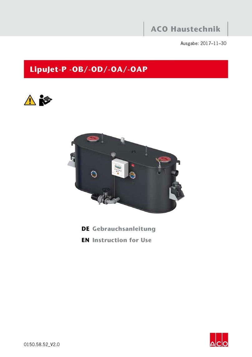
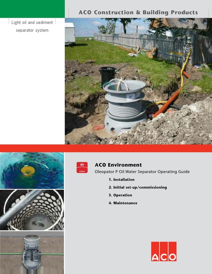
ACO NS3/450 Owner's manual

ACO Environment
Installation
Operation
Maintenance
Oleopator P Oil-Water Separator

888-490-9552 www.acousa.com
OLEOPATOR P OPERATION MANUAL
1
Contents
Oleopator P Series 1
System Components 2
1. Safety Considerations 3
1.1 Designated Use 3
1.2 Qualications of Personnel 4
1.3 Personal Safety Equipment 4
1.4 Responsibility of Owner 4
2. Installation 5
2.1 Onsite Handling 5
2.2 Ground Conditions 6
2.3 Separator Positioning 6
2.4 Installation 9
3. Initial Set-Up 11
3.1 Prior to Filling the System 11
3.2 Filling Separator System 12
4. Operation 13
4.1 Entering the Separator 13
4.2 Oil/Sludge Level Sensors 13
5. Maintenance 14
5.1 Maintenance Schedule 14
5.2 Cleaning Coalescence Units 15
5.3 Oil/Sludge Disposal 16
5.4 General Inspection 16
6. Alarms Assembly & Initialization 17
6.1 Sensor Support Position 17
6.2 Sensor Setting 18
6.3 Simple Commissioning 19
6.4 Advanced Commissioning 20
7. askACO 21
Oleopator P Series
ACO Oleopator P is a range of oil
separators that allow sediments and
oils to be separated out simultaneously
in one tank. Separator systems are
available with a range of dierent sludge
and oil capacities to suit specic site
requirements.
Alarm sensor systems are available to
notify personnel when maintenance is
required. Oil level sensors are required
for compliance with UL 2215.
Class I Light Oil Separators
An included coalescence unit traps oil
drops that are too small to oat to the
surface naturally and coalesces them to
form larger oil drops capable of being
separated out. These separators are
certied capable to EN 858 and capable
of achieving euent quality of 5 ppm.
Bypass Separators
A bypass version is available for when full
treatment of large ows is not required.
The unit will fully treat ows until it
reaches maximum inow volume (GPM),
at which point additional inow bypasses
the separator and diverts directly to the
outlet pipe. Typically most pollutants
are washed into the separator during
the initial ow so euent quality is not
drastically aected.
Product Information
Detailed product information is available
in associated spec info sheets, the EN100
ACO Environment Catalog, or
www.acoenvironment.us.

888-490-9552 www.acousa.com
OLEOPATOR P OPERATION MANUAL
ACO ENVIRONMENT
2
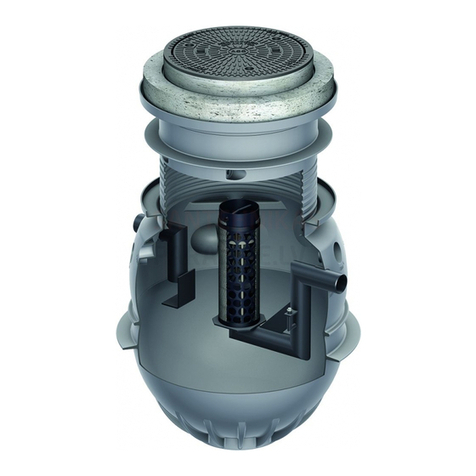
System Components
1. Cover
2. Load Distribution Plate*
3. Extension Shaft
4. Identication Plate
5. Coalescence Unit
6. Float
7. Bypass Inlet**
8. Inlet Connection
9. Inlet Pipe
10. Bae Plate
11. Tank
12. Outlet Pipe
13. Sampler Connection
14. Outlet Connection
15. Bypass Outlet**
* Load Class D only. Cast in place by others.
** Optional; sold as separate item.
2
3
3
715
1
1
4
9
11
10 12
6
14
5
13
8
Heavy Duty
Light Duty

888-490-9552 www.acousa.com
OLEOPATOR P OPERATION MANUAL
3
The safety guidelines in this chapter are to be read before using the separator. Serious
injuries or death could occur as a result of misuse.
1.1 DESIGNATED USE
Areas of Application
Oleopator separators are designed
to remove mineral light liquids from
wastewater.
Applications where mineral oils or mineral
light liquids are able to enter the sewer
system should have separator systems
connected downstream from drainage
collection points. Such applications
include gas stations, parking lots,
roadways, car washes, engine washes,
garages, vehicle recycling, scrap yards,
fueling stations, tank pits and transformer
stations.
Stormwater from areas where no light
liquids accumulate—such as roofs and
courtyards—should not be fed into the
separator.
Separators should be installed such that
no light liquids can escape in the event
of backow from the sewer or automatic
closure of the oat. An automatic alarm
may be required. Regulations may vary
by state.
No soaps are allowed in water entering
the separator, with the exception of
specially-formulated soaps with short
emulsication periods. No centrifugal
pumps that lead to emulsication of oils
are allowed prior to the separator.
Limitations
The separators are not to be installed for
residential wastewater.
When delivering wastewater into
the public sewer system, the local
hydrocarbon limits should be observed.
Further treatment may be required.
Foreseeable Misuse
No substances that pollute the water or
limit the functionality of the separator
should be introduced into the separator,
including but not limited to the
following:
wastewater containing feces
wastewater containing animal or
vegetable greases
wastewater in which a considerable
amount of stable emulsions is present
1Safety Considerations

888-490-9552 www.acousa.com
OLEOPATOR P OPERATION MANUAL
ACO ENVIRONMENT
4
1.2 QUALIFICATIONS OF PERSONNEL
All work performed on the separator
equipment is to be carried out by trained
personnel.
1.3 PERSONAL SAFETY EQUIPMENT
Personal safety equipment is necessary
for a variety of works on the separator.
1.4 RESPONSIBILITY OF OWNER
The owner is responsible for complying
with the following points:
Only operate the separator according
to regulations and in proper
conditions.
Ensure that protection devices are
functional.
Adhere to a scheduled maintenance
program and immediately repair
faults. Only repair faults yourself if
the measures are described in these
operating instructions. Contact ACO
for all other measures.
Inspect data plate on the separator for
completeness and legibility.
Adequate personal safety equipment
must be available and used.
Provide complete and legible
operating instructions at the
separator’s site of installation and
training based on this.
Only employ qualied and authorized
personnel.
HEALTH & SAFETY
Safety instructions are intended to
prevent injury to personnel or damage to
equipment and must be read before any
maintenance is performed.
The separated oils and any vapors are
ammable and/or combustible. Care
must be taken whenever the system is
opened.
All safety instruction labels must be
replaced if they become detached or
illegible.
Gas concentrations MUST be tested
before entering the separator;
breathing apparatus is recommended
for all personnel entering separator.
Safety lines, harnesses and radios/
whistles are advised if entering
separator.
Smoking and naked lights are
strictly forbidden anywhere in area
surrounding the system.
Installed devices (e.g. baes, inlet and
outlet parts, coalescence unit, etc.)
are intended for operation of separator
system and are not load bearing.
They must not be used as steps,
footholds or resting places for cleaning
equipment etc.
The separator system is dened as a
Zone 0 Explosion Hazard Area. Only
authorized, properly trained personnel
are permitted to perform work on the
electrical components of the separator
(where used).
Contact with wastewater
containing light liquids—e.g. during
maintenance—can lead to dry, irritated
skin, skin infections, headaches,
dizziness, nausea, vision problems,
loss of consciousness, and—in serious
cases—death. Ensure proper protective
clothing is used and immediately wash
any exposed skin.
888-490-9552 www.acousa.com
OLEOPATOR P OPERATION MANUAL
5
2
Oleopator P separators are intended
for in-ground installation. Care must be
taken to determine correct installation to
take into account site loadings and trac
patterns. Details are provided for both
light duty and heavy duty applications.
Inspect Oleopator P upon delivery and
before installation to check for damage
that may have occurred during shipping
or at the job site prior to installation.
Light oil separators can be extremely
large (depending upon ow and holding
capacity). Ensure correct equipment is
available for proper unloading, moving
around site and lowering into required
nal position.
Remove oats and lters during
installation and protect separator
openings from site run-o as stones and
debris may cause surface damage inside
the separator.
Installation
2.1 ONSITE HANDLING
Personnel
Carry separator with two people using
the circular ring as a grip and pipe
connections for additional stability.
Not suitable for single person lift.
Crane
Sling attachment points are provided
for proper handling of the tank. Do not
transport the separator with extension
shaft sections and/or covers assembled.

888-490-9552 www.acousa.com
OLEOPATOR P OPERATION MANUAL
ACO ENVIRONMENT
6
2.2 GROUND CONDITIONS
Where groundwater is present, certain
additional measures may need to be
taken to prevent lifting.
Light Duty Applications - if
groundwater level is less than 19.7" (500
mm) below grade no additional measures
are required. Where groundwater level
is higher than 19.7" (500 mm) below
grade, an on-site 63" (1600 mm) dia x 6"
(152 mm) thick concrete ring is cast
in-situ over the large, lower tank ridge
(see diagram below) to avoid oating.
Heavy Duty Applications - no
additional measures are required.
1
2
2.3 SEPARATOR POSITIONING
The purpose of a separator is to collect
light oils for proper disposal. Timely
emptying and maintenance is critical
for eective operation. Alarm systems
can help ensure light oils and sludge
are removed in a timely fashion and can
alert appropriate personnel to potential
maintenance issues.
Alarm failure (or Failure to Action alarm
alerts) and backow from sewers are
potential causes of operation error and
pollution. These can be overcome in
certain applications by adjusting the
height of the separator relative to the
collection vessel/drain. Super-elevated
positioning is where the cover of the
separator is higher by a minimum height
(V) than the collection point and inlet.
V
max 19.7"
(500 mm)
max 6.0"
(152 mm)
min Ø 63" (1600 mm)
1
2
V - Super-elevated Positioning
Size Pedestrian
in (mm)
Heavy Duty
in (mm)
Cover Only Cover & Shaft Cover & Shaft
OLEOPATOR P MODEL
NS3/450 1.78 (45) 2.75 (70) 5.90 (150)
NS3/670 1.78 (45) 2.75 (70) 5.90 (150)
N 3/950 1.78 (45) 2.75 (70) 5.90 (150)
NS6/660 1.57 (40) 2.56 (65) 5.71 (145)
NS6/1210 1.57 (40) 2.56 (65) 5.71 (145)
NS10/1080 1.97 (50) 2.95 (75) 6.10 (155)
see table below
for value of V

888-490-9552 www.acousa.com
OLEOPATOR P OPERATION MANUAL
7
INSTALLATION SITUATION
Super-Elevated
Positioning No No
Alarm System No Yes
OPERATING SITUATIONS
Ready for use
Normal operation Normal operation
Max Oil =
Float Closure =
Blockage
Oil will leak from cover Alarm will signal and
oil will leak from cover
Backow from sewer
Oil will leak from cover
unless a backow
prevention pump is
used downstream from
separator
Alarm will signal and oil
will leak from cover unless
a backow prevention
pump is used downstream
from separator
2.3 SEPARATOR POSITIONING (cont.)

888-490-9552 www.acousa.com
OLEOPATOR P OPERATION MANUAL
ACO ENVIRONMENT
8
INSTALLATION SITUATION
Super-Elevated
Positioning Yes Yes
Alarm System No Yes
OPERATING SITUATIONS
Ready for use
Normal operation Normal operation
Max Oil =
Float Closure =
Blockage
Oil will stay in separator,
wastewater will ood from
collection xture
Alarm will signal and oil
will stay in separator,
wastewater will ood from
collection xture
Backow from sewer
Oil will stay in separator,
wastewater will ood from
collection xture
Alarm will signal and oil
will stay in separator,
wastewater will ood from
collection xture

888-490-9552 www.acousa.com
OLEOPATOR P OPERATION MANUAL
9
2.4 INSTALLATION
Light Duty Installations
1. Excavate area 60" (1524 mm) wider
and 12" (305 mm) deeper than the
separator; this allows for a 12" (305
mm) aggregate base compacted to
Proctor density 97%.
2. Check level of unit and inverts of
inlet/outlet pipes.
3. Backll in 12" (305 mm) layers around
unit to the level of inlet/outlet pipes
(backll should be 2-16 mm sand/
gravel) and compact to Proctor
density 97%; take care to not damage
separator when compacting ll.
4. Connect inlet/outlet pipes - pipes
should be resistant to hydrocarbons.
Flexible couplings will be required
as inlet/outlet pipes are metric
dimensions.
5. Inlet pipes should be installed with
as few bends and slopes as possible
to prevent blockages and reduce
turbulence of incoming wastewater.
6. Install extension shaft (if used) - cut to
required height, place provided seal
in lowest notch of remaining section.
Grease seal and tank collar with acid-
free grease to ensure watertight seal.
7. Install wiring conduit for alarm system
(if used).
8. Recheck levels.
9. Continue to backll and compact.
10. Place cover with 4" (102 mm) deep
concrete collar onto shaft/tank
assembly.
11. Install alarm sensors (if used).
Heavy Duty Installations
1. Excavate area 60" (1524 mm) wider
and 12" (305 mm) deeper than the
separator; this allows for a 12" (305
mm) aggregate base compacted to
Proctor density 97%.
2. Check level of unit and inverts of
inlet/outlet pipes.
3. Backll in 12" (305 mm) layers around
unit to the level of inlet/outlet pipes
(backll should be 2-16 mm sand/
gravel) and compact to Proctor
density 97%; take care to not damage
separator when compacting ll.
4. Connect inlet/outlet pipes - pipes
should be resistant to hydrocarbons.
Flexible couplings will be required
as inlet/outlet pipes are metric
dimensions.
5. Inlet pipes should be installed with
as few bends and slopes as possible
to prevent blockages and reduce
turbulence of incoming wastewater.
6. Install extension shaft - cut to
required height, place provided seal
in lowest notch of remaining section.
Grease seal and tank collar with acid-
free grease to ensure watertight seal.
7. Install wiring conduit for alarm system
(if used).
8. Continue backlling up to 8" (203
mm) below top of access shaft.
9. Install reinforcement, form and pour
concrete load distribution plate
8" (203 mm) thick and extending
13.75" (350 mm) around shaft in all
directions (see next page for details).
10. Install cover, frame and concrete
adaptor plate to ensure it is held
securely in place.
11. Install alarm sensors (if used).

888-490-9552 www.acousa.com
OLEOPATOR P OPERATION MANUAL
ACO ENVIRONMENT
10
Load Distribution Plate
Ø 53.15"/25.60" x 8.00"
(1350 mm/650 mm x 203 mm)
Cross-Section
Ø 53.15" (1350 mm)
Ø 25.60" (650 mm)
8.00" (203 mm)
13.78"
(350 mm)
13.78"
(350 mm)
6.00"
(152 mm)
4.50"
(115 mm)
Concrete: 5,000 psi (35 MPa)
Concrete Steel: #4 Rebar (10 M)
Concrete Cover: 1.18" (30 mm)
(35) #4 Rebar @
3.15" (80 mm) Stirrups
(3) #4 Rebar (top)
(3) #4 Rebar (bottom)
Typical Reinforcement Plan
Ø 53.15" (1350 mm)
Ø 25.60" (650 mm)
8.00" (203 mm)
13.78"
(350 mm)
13.78"
(350 mm)
6.00"
(152 mm)
4.50"
(115 mm)

888-490-9552 www.acousa.com
OLEOPATOR P OPERATION MANUAL
11
3Initial Set-Up/Commissioning
3.1 PRIOR TO FILLING THE SYSTEM
Ensure all required air and water
tests are completed before nished
installation of unit.
All system components—baes,
coalescence units and internal piping—
must be inspected to ensure that
nothing is missing, loose or damaged.
Install provided identication plate
in the maintenance shaft as shown in
the diagram below. This will assist in
future maintenance and ordering of
consumables etc.
Identication plate provides:
Separator type identication
Nominal size
Class
Number of the LGA Test report
Volume of separator and sludge trap
Maximum storage volume and
maximum thickness of light oil layer
Maximum permissible sludge thickness
Fixing screw
Chain
Identification plate
Manhole ring
Cover levelling ring
Fixing screw
Chain
Identification plate

888-490-9552 www.acousa.com
OLEOPATOR P OPERATION MANUAL
ACO ENVIRONMENT
12
3.2 FILLING SEPARATOR SYSTEM
System MUST NOT be lled until
installation is complete and all
mortared and sealed joints have been
allowed to cure properly.
System should be cleaned before use.
Float must be removed before the
separator is lled. Failure to do so may
cause the outlet pipe to be blocked by
the oat and improper functioning of
the separator may occur.
Removing Float & Coalescent Unit
1. Lift the coalescence unit out of
separator via extension system.
2. Remove oat located in the
supporting cage.
3. Store coalescence unit and oat in
water, in safe place until separator
is lled and they are required for
reinstallation.
Filling Procedure
1. Ensure inlet and outlet valves are
open.
2. Fill the separator with clean water,
either via manhole cover or inlet/
trench drain.
3. When the separator is full, water will
start to ow out of the outlet; this can
be identied from the outlet sampling
chamber/hose (if used), or when
water reaches the outlet invert using
a depth gauge stick.
4. Allow water to continue to run to
check for blockages in the outlet
pipe. If water depth remains constant
then no blockage exists. If water starts
to back-up, then an investigation into
the cause of blockage is required.
5. Ret oat and coalescent unit.
6. Fit and check alarm sensors if used.
1
2
3
4
1
2
3
4

888-490-9552 www.acousa.com
OLEOPATOR P OPERATION MANUAL
13
Operation
4
ACO Oleopator P is designed to be easy to operate with minimal intervention required.
4.1 ENTERING THE SEPARATOR
All relevant local accident prevention
regulations must be strictly observed
when entering a separator. There is no
need to enter a separator for regular
maintenance.
Size NS 3 to NS 10 Separators can be
entered via maintenance shaft located
above the oat cage. The following steps
ensure easy accessibility:
1. Clean out separator sludge/oils.
2. Remove the coalescence unit (Class I
separators only).
3. Remove the oat.
4. Pull the oat cage from the holder
and remove it (if possible).
The separator can now be entered.
Once all work has been carried out,
ensure original condition of separator is
reinstated:
1. Place the oat cage back in the holder
(taking care to properly align pins in
the cage).
2. Replace oat after the separator has
been lled.
3. Install the coalescence unit (Class I
separators only).
4.2 OIL/SLUDGE LEVEL SENSORS
An optional alarm system makes
operation easier and ensures compliance
with UL2215. It does not replace visual
maintenance but ensures timely disposal
of oil and/or sludge to guarantee
continued operation of the system.
Sensors will signal when:
Oil has reached 80% maximum
capacity (once oil reaches 100%
capacity the oat will sink and close
the outlet pipe)
Sludge has reached 50% maximum
capacity (once sludge reaches 100%
capacity the inlet pipe will become
blocked)
When liquids in the separator reach a
specic level, alarm indicates that the
outlet pipe is blocked
When any of these events occur a signal
is sent to the building management
system which can send out audio, visual
and SMS alerts to ensure maintenance
can be carried out before the separator
system fails.

888-490-9552 www.acousa.com
OLEOPATOR P OPERATION MANUAL
ACO ENVIRONMENT
14
Maintenance
5
5.1 MAINTENANCE SCHEDULE
Table below provides a recommended schedule of maintenance and inspection to
ensure trouble-free operation of the separator.
Note: Refer to 4.1 Entering the Separator (pg 13) before maintenance is undertaken.
Measures What must
be done?
Who should
do it? Interval
Visual Inspection &
Maintenance
■Check proper functioning of self-
actuating closure and coalescence
unit in the separator
■Measuring thickness and volume
of oil layer separated out at top of
separator
■Measuring height of sludge layer in
sludge trap
■Empty and clean separator
as required (see disposal
requirements)
■Remove any coarse oating material
■Inspect all components of alarm
system (if used)
■Immediately rectify any faults
identied
■Report ndings and any work
carried out in operating
Properly
Qualied
Operative
Maximum every 6 months
and immediately after any
large oil spill incident and/
or excessive rainstorm.
Disposal Service The separator must be emptied when:
■80% of the maximum oil storage
volume has been reached, and/or
■50% of the max sludge trap volume
has been reached
Properly
Authorized
Disposal
Company
As required, but at least
every year.
Observe local municipal
and environmental
requirements.
General Inspection ■Separator must be emptied and
contents properly disposed of
■Inside of separator must be cleaned
■Check proper functioning of self-
actuating closure
■Check water-tightness of the system
■Check condition of installed devices and
interior surface condition
Properly
Qualied
Technician
Prior to initial use and then
every ve years.

888-490-9552 www.acousa.com
OLEOPATOR P OPERATION MANUAL
15
5.2 CLEANING COALESCENCE UNITS
Coalescence unit must be removed
periodically for cleaning. The separator is
not functional during this process.
1. Ensure inlet/outlet valves are closed.
2. Pull the coalescence unit up above
water level in the separator, using a
hoist where necessary.
3. Allow water to drip into the separator
before removing the coalescence
unit.
4. Clean the coalescence unit in a
bucket or other appropriate area
to contain wastewater for proper
disposal (contaminated water can be
poured back into the separator).
5. Completely remove all dirt* by
spraying with clean water from either:
a) minimum ¾" hose, under mains
pressure (minimum 58 psi), or
b) high pressure device using cold
water at a maximum of 870 psi.
6. Rinse thoroughly with a high pressure
device with max 870 psi and 140 °F
(60 °C).
Removing Coalescence Mats
Coalescence mats are attached to a
supporting basket at the top and bottom
of the coalescence unit with tensioners
and Velcro strips (uy side outwards).
Once these supports are removed, mats
can be unwound from basket. Mats only
need to be removed from the basket if
soiling is particularly bad.
Replacing Coalescence Mats
To replace coalescence mats, wrap the
mat around the supporting basket and
replace tensioners and Velcro straps
(uy side outwards). When wrapping
the mat around the basket ensure
no openings are left that could allow
wastewater to ow through untreated.
Avoid wrapping coalescence mats too
tightly to prevent damage.
Tip – Lengthy operational hold-ups can be
prevented by swapping dirty coalescence
units for clean back-up/spare coalescence
unit. The dirty coalescence unit can be
stored in a water-lled container until—to
prevent dirt drying hard onto unit—it can
be cleaned.
* Only use cleaning products when
absolutely necessary. Ensure cleaning
agent will not damage the separator by
consulting cleaning product MSDS details
for suitability.

888-490-9552 www.acousa.com
OLEOPATOR P OPERATION MANUAL
ACO ENVIRONMENT
16
5.3 OIL/SLUDGE DISPOSAL
Maximum levels for emptying the
separator are when:
80% of maximum oil storage has been
reached, and/or
50% of maximum sludge trap volume
has been reached.
The identication plate shows
maximum thicknesses of each layer (the
identication plate is located inside the
separator).
Even if levels remain below these limits,
the separator should be emptied at least
every year.
Contents of the separator must be
disposed of by an authorized disposal
company.
Care must be taken not to damage
inside walls and internal equipment of
the separator.
Rinse down walls and the base of the
separator using hot water to loosen
hardened solids and suction out left-
over slurry.
Rell the separator with clean
cold water, following initial set-up
procedure (See 3.2 Filling Separator
System on pg. 12).
5.4 GENERAL INSPECTION
Prior to initial use and thereafter at
regular ve-year intervals, a properly
qualied technician* must inspect
the separator to ensure it is in good
condition and operating properly.
The separator must be completely
emptied and cleaned before general
inspection can be carried out.
An integral part of every general
inspection is a water-tightness test carried
out in accordance with EN 858-2.
1. Close inlet & outlet pipes.
2. Fill the separator with water until full.
3. Check for changes in water level
indicating possible leaks.
4. Investigate/repair/replace as required.
* "Properly qualied technician" is
dened as equipped sta of independent
companies, independent experts, or other
institutions with certied special technical
knowledge on the operation, maintenance
and testing of the separators described
here.

888-490-9552 www.acousa.com
OLEOPATOR P OPERATION MANUAL
17
ACO Separators
Alarms Assembly Instructions
1 Fitting position of sensor support
red circles.
CAUTION Do not mount support above inlet
or outlet.
2 Sensor setting
sensors. The detail shows the extension of the sensor ca-
“idOil-30 Installa-
”. The different sensors
−H3,
referring to = upper edge of inlet submersible pipe (1).
(For dimensions, see below table).
Alarms Assembly & Initialization Instructions
6
6.1 FITTING POSITION OF SENSOR SUPPORT
The illustrations below depict correct tting position of sensor support with separators
without and with top system. The sensor cables or the extension cables (optional) are
laid up to the monitoring device through an in-situ empty tube.
The preferred tting positions are marked by red circles.
CAUTION: Do not mount support above inlet or outlet.
ACO Separators
Alarms Assembly Instructions
1 Fitting position of sensor support
red circles.
CAUTION Do not mount support above inlet
or outlet.
2 Sensor setting
sensors. The detail shows the extension of the sensor ca-
“idOil-30 Installa-
”. The different sensors
−H3,
referring to = upper edge of inlet submersible pipe (1).
(For dimensions, see below table).
Separator without Access Shaft Separator with Access Shaft

888-490-9552 www.acousa.com
OLEOPATOR P OPERATION MANUAL
ACO ENVIRONMENT
18
6.2 SENSOR SETTING
The illustration below depicts the completely mounted sensors. The detail shows the
extension of the sensor cable; also see hanging instructions in the idOil-30 Installation
and Maintenance Manual. The height of the sensors is relative to the upper edge of the
inlet pipe and must be set per the table and diagram below.
ACO Separators
Alarms Assembly Instructions
1 Fitting position of sensor support
red circles.
CAUTION Do not mount support above inlet
or outlet.
2 Sensor setting
sensors. The detail shows the extension of the sensor ca-
“idOil-30 Installa-
”. The different sensors
−H3,
referring to = upper edge of inlet submersible pipe (1).
(For dimensions, see below table).
1
1
Oleopator P Model
H1 Sludge Sensor
Height
in (mm)
H2 Oil Sensor
Height
in (mm)
H3 High Level
Sensor Height
in (mm)
NS3/450 30.32 (770) 11.02 (280) 1.38 (35)
NS3/670 34.25 (870) 11.02 (280) 1.38 (35)
NS3/950 38.19 (970) 11.02 (280) 1.38 (35)
NS6/660 34.65 (880) 12.99 (330) 0.59 (15)
NS6/1210 46.46 (1180) 12.99 (330) 0.59 (15)
NS10/1080 46.46 (1180) 12.99 (330) 0.59 (15)

888-490-9552 www.acousa.com
OLEOPATOR P OPERATION MANUAL
19
6.3 SIMPLE COMMISSIONING (MANDATORY)
To initialize alarm, a commissioning procedure must be followed:
1. Connect all required sensors.
2. Power up alarm unit.
3. Press sensor identication button on panel.
ACO Separators
Sensor Initialization Instructions
3 Simple Commissioning (Mandatory)
To inialize alarm, a commissioning procedure must be followed:
1. Connect all required sensors.
2. Power up alarm unit.
3. Press sensor idencaon buon on panel. (Figure 1.)
4 Advanced Commissioning (Optional)
• Set Date/Time
• Add Unit Name
• Access Alarm Log
1. Press reset buon on panel twice to inialize panel wi signal.
2. Connect phone/tablet/computer to panel wi signal “idOil30”.
Network password will be ve zeros (00000) + nal eight digits
of serial number found on panel.
(i.e. if serial number is 8540564_1112118J, the password
would be 000001112118J)
3. Open web browser of your device and enter the web address
of: 192.168.0.1
4. A connecon to the alarm unit has now been formed, sengs
can be updated, wi signal will auto shuto aer 10 minutes
of non-use.
Note: Certain sengs may require an addional password on the
browser interface, this password is: 1234
See Labkotec idOil30 installaon manual included with alarm for
addional instrucons and details.
ACO Systems, Ltd.
1-2880 Brighton Rd.
Oakville, ON L6H 5S3
T 905-829-0665
F 905-829-2908
www.acoenvironment.ca
1
1
This manual suits for next models
5
Table of contents
Other ACO Water Filtration System manuals

ACO
ACO Lipumax-P User manual

ACO
ACO Oleopator P Series User manual

ACO
ACO LipuJet-P User manual

ACO
ACO UNIFACE GS,SS/FR User manual

ACO
ACO UNIFACE GS User manual

ACO
ACO Oleolift-C User manual

ACO
ACO Lipumax-C-FST User manual

ACO
ACO Oleosmart-C-OST Manual

ACO
ACO LipuMobil-P Series User manual

ACO
ACO ECOJET User manual
Popular Water Filtration System manuals by other brands

Dantherm
Dantherm HRV 5 Service manual

Life
Life 7600/ 8100/ 8200 user manual

Watts Premier
Watts Premier DELUXE PLUS Installation, operation and maintenance manual

Oase
Oase BioMaster 250 operating instructions

Evo-water
Evo-water UO small 150l Manual use and maintenance

Hayward
Hayward hydrorite uvo3 owner's manual