Chapter 1 Motherboard Description /7Chapter 1 Motherboard Description /7
Chapter 1 Motherboard Description /7Chapter 1 Motherboard Description /7
Chapter 1 Motherboard Description /7
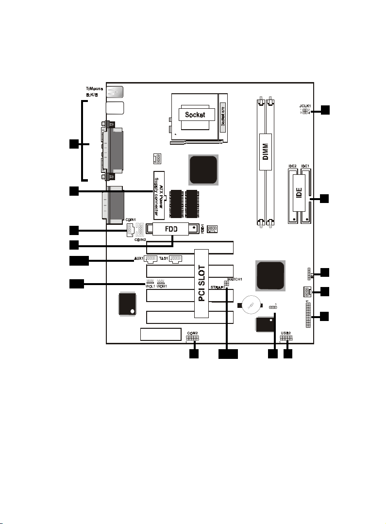
1.3 Motherboard Connectors
7
18
9
4,5
1.Back Pannel I/O Connectors1.Back Pannel I/O Connectors
1.Back Pannel I/O Connectors1.Back Pannel I/O Connectors
1.Back Pannel I/O Connectors 2.CD Audio-In Connector2.CD Audio-In Connector
2.CD Audio-In Connector2.CD Audio-In Connector
2.CD Audio-In Connector
3.Front COM2 Connector3.Front COM2 Connector
3.Front COM2 Connector3.Front COM2 Connector
3.Front COM2 Connector 4.Wake-On LAN Connector4.Wake-On LAN Connector
4.Wake-On LAN Connector4.Wake-On LAN Connector
4.Wake-On LAN Connector
5.Wake-On Modem Connector5.Wake-On Modem Connector
5.Wake-On Modem Connector5.Wake-On Modem Connector
5.Wake-On Modem Connector 6.Front Panel Connector6.Front Panel Connector
6.Front Panel Connector6.Front Panel Connector
6.Front Panel Connector
7.Fan Connectors(Fan1/2/3)7.Fan Connectors(Fan1/2/3)
7.Fan Connectors(Fan1/2/3)7.Fan Connectors(Fan1/2/3)
7.Fan Connectors(Fan1/2/3) 8.Floppy Connector8.Floppy Connector
8.Floppy Connector8.Floppy Connector
8.Floppy Connector
9.IDE Connectors9.IDE Connectors
9.IDE Connectors9.IDE Connectors
9.IDE Connectors 10.IR Connector10.IR Connector
10.IR Connector10.IR Connector
10.IR Connector
11.Front USB2 Connector11.Front USB2 Connector
11.Front USB2 Connector11.Front USB2 Connector
11.Front USB2 Connector 12.ATX Power Connector12.ATX Power Connector
12.ATX Power Connector12.ATX Power Connector
12.ATX Power Connector
13.CPU Freq. Selection(JCLK1)13.CPU Freq. Selection(JCLK1)
13.CPU Freq. Selection(JCLK1)13.CPU Freq. Selection(JCLK1)
13.CPU Freq. Selection(JCLK1) 14.Speaker Selection(WATCH1)14.Speaker Selection(WATCH1)
14.Speaker Selection(WATCH1)14.Speaker Selection(WATCH1)
14.Speaker Selection(WATCH1)
15.AUX Audio in Connector(AUX1)16.Telephone Connector(TAD1)15.AUX Audio in Connector(AUX1)16.Telephone Connector(TAD1)
15.AUX Audio in Connector(AUX1)16.Telephone Connector(TAD1)15.AUX Audio in Connector(AUX1)16.Telephone Connector(TAD1)
15.AUX Audio in Connector(AUX1)16.Telephone Connector(TAD1)
17.AC97 Serial data out(STRAP1)17.AC97 Serial data out(STRAP1)
17.AC97 Serial data out(STRAP1)17.AC97 Serial data out(STRAP1)
17.AC97 Serial data out(STRAP1)
18.CMOS Function Selection(CMOS1)18.CMOS Function Selection(CMOS1)
18.CMOS Function Selection(CMOS1)18.CMOS Function Selection(CMOS1)
18.CMOS Function Selection(CMOS1)
10
1
3
12
6
2
13
11
8
USB1
COM1
VGA
Printer
FAN2
FAN1
JACK1
JACK2
JACK3
GAME1
Intel
Intel
PANEL1
FAN 3
CNR SLOT
CMOS1
DIMM2
DIMM1
I/O CHIP
BIOS
1
PCI2
PCI3
PCI4
PCI1
2MB SDRAM
1MB*16 SDRAM
2MB SDRAM
1MB*16 SDRAM
Option
15,16
14,17