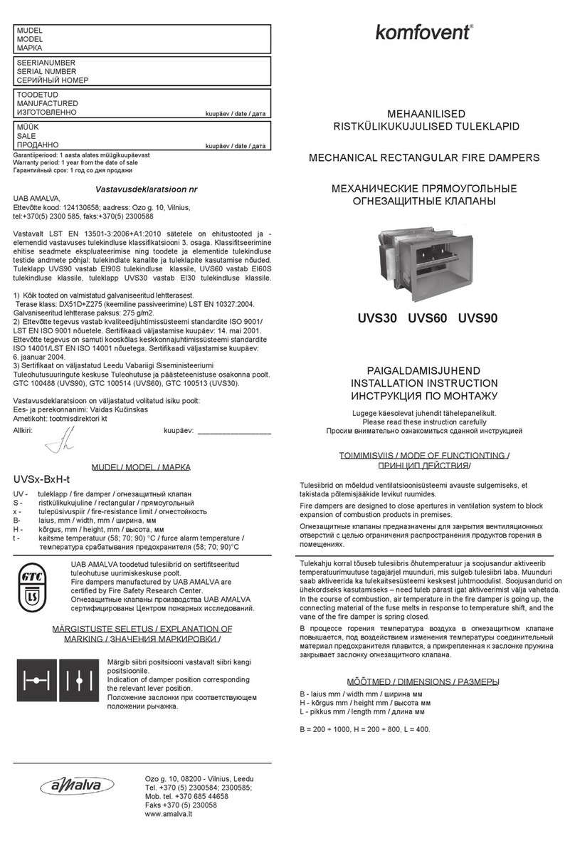
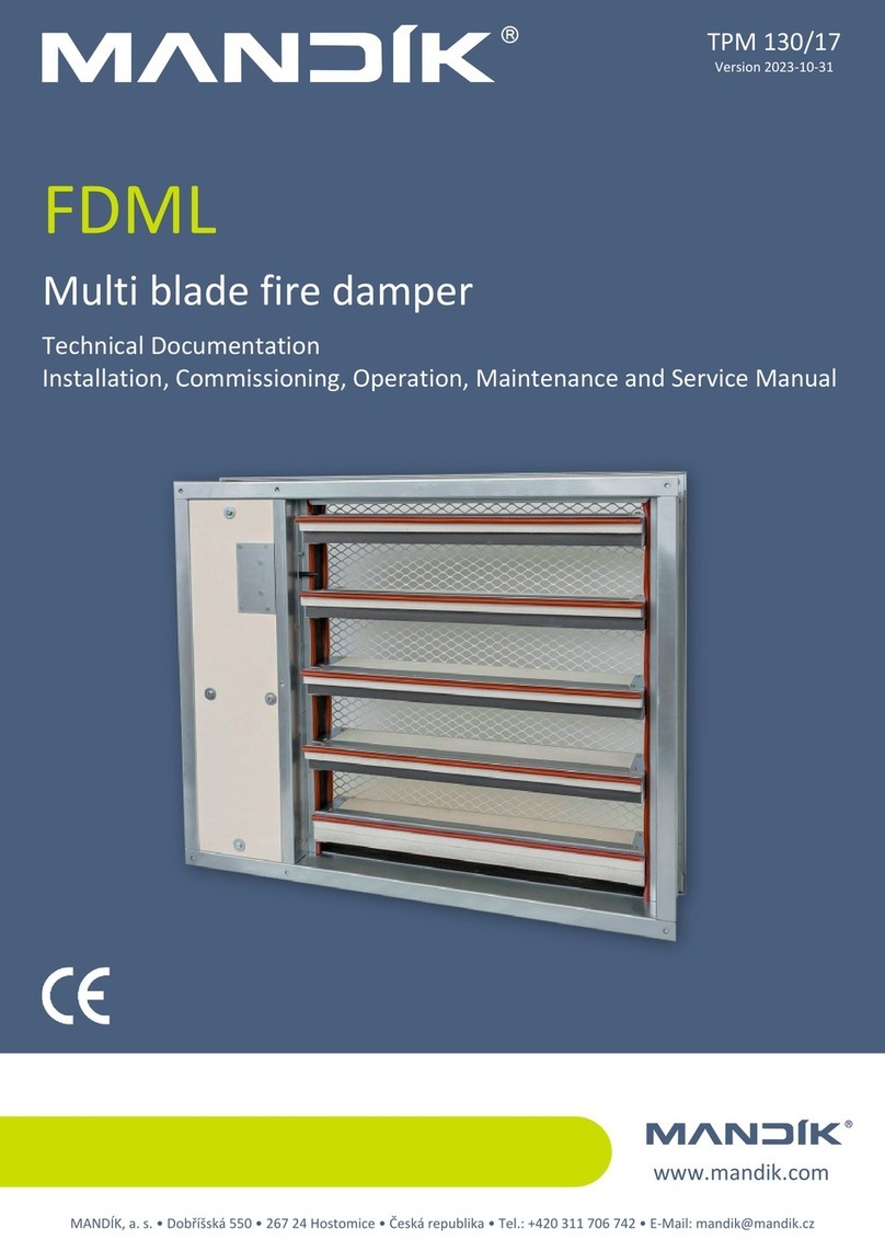
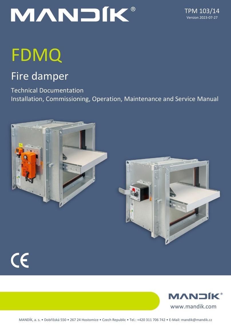
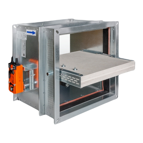
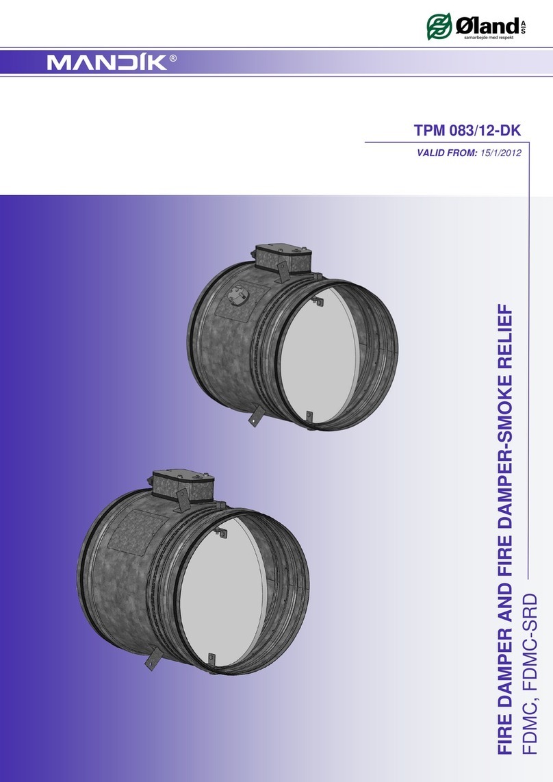
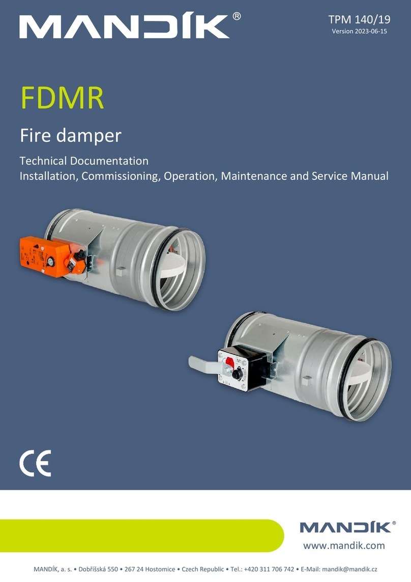
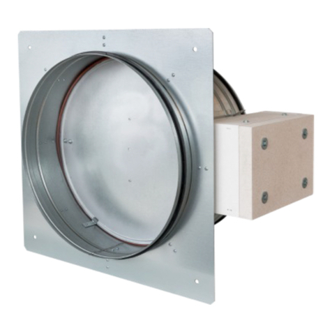
Mandik FDML User manual


1
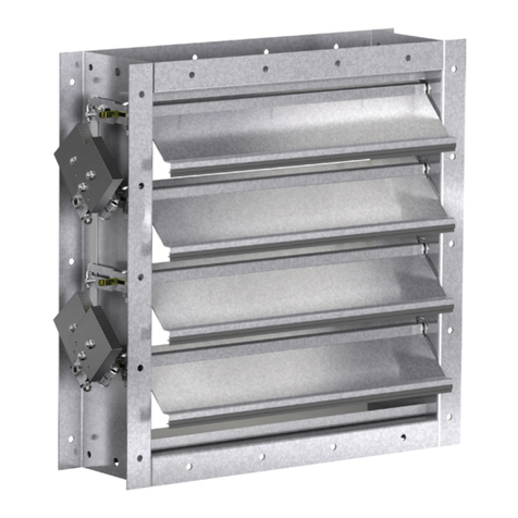
These specifications define the line of produced sizes, main dimensions, models and scope of application of FDML multi blade fire dampers.
The specifications are binding for design, manufacture, delivery, storage, assembly, operation, maintenance and serviceability checks.
Description........................................................................................................................................................
2
Design...............................................................................................................................................................
3
Material.............................................................................................................................................................
3
Dimensions and weight.....................................................................................................................................
4
Electrical components, wiring diagram..............................................................................................................
8
Installation and placement.................................................................................................................................
13
Checks..............................................................................................................................................................
18
Tests.................................................................................................................................................................
18
Logistic data......................................................................................................................................................
18
Guarantee.........................................................................................................................................................
18
Assembly...................................…......................................................…..........................................................
18
Putting into operation and serviceability checks...................................…........................................................
18
Spare parts......................................…..............................................................................................................
18
Nameplate..........................................…...........................................................................................................
19

2
FDML multi blade fire dampers are in motor-driven versions with servo drives and they have the following two main applications:
■They are applied as fire closures without following air condition duct with cover grids for closure of vents in fire dividingwalls,
constructions, elevator and other shafts, cable and other channels preventing spread of fire heat and other combustion
products.
■If applied as multi blade fire damper with air condition connecting pipes from both ends (without grids) or with connecting
pipe at one end (1x grid) they prevent spreading of heat and combustion products through such piping system.
If the damper is hit with fire it will automatically (or remotely as the case may be) be closed and spread of fire from one fire
sector to another will be prevented. Damper blades automatically close air flow using servo check spring. The servo check
spring is put into operation at activation of thermo-electric actuator by pressing reset button or with interruption of servo
feeding. Once the blades have been closed the damper is sealed using rubber seal against fume penetration. At the same
time damper blade is placed in a material which increases its volume by actuating higher temperature and seals the damper
hermetically. Dampers are not furnished with inspection chambers. If these dampers are used as dampers for simple
maintenance and revision they must be completed with connecting inspection equipment installed just behind the damper.
Plaster / Mortar Rigid wall structure, min. thickness 100 mm EI 90 S, E 120 S
Mineral wool (density min.140kg/m³) furnished
with fire stop SEALANT (min. thickness 1 mm)
(i.e. HILTI Acrylic sealant CFS-S ACR) and fire
stop COATING, min., thickness 1 mm
(for instance HILTI Firestop coating CFS-CT).
Rigid wall or plasterboard structure, min.
thickness 100 mm EI 90 S, E 120 S
■CE certification according to EN 15650
■Tested according to EN 1366-2
■Classified according to EN 13501-3+A1
■Fire resistance EI 90 S, E 120 S
■Damper casing air leakage category B, air leakage through damper blade category 3 according to EN 1751
■Cycling tests C10000 according to EN 15650
■Maximum airflow velocity 12m/s.
■Maximum pressure difference on damper blade 1500 Pa.
■Even distribution of air flow in complete damper cross section area.
■Damper operating characteristics are independent on airflow direction through the damper. The damper can be installed with
blade axis vertically or horizontally, temperature sensor must always be in damper upper part.
■Dampers are intended for airs without abrasive, chemical and sticky admixtures.
■Dampers are intended for environments protected from weathering with classification of climatic conditions category 3K5,
without condensing, icing, ice coating, water also from other sources different from rain and with temperature limits - 10 to
+50°C according to EN 60 721-3-3 amend..A2. When the damper is furnished with electrical elements the temperature
scope is reduced according to temperature limits of applied electrical elements.
■Optical smoke detector MHG 231 with socket MHY 734.031 is intended for environments protected from weathering of
categories 3K5/3Z1/3Z8/3B1/3C2/3S1/3M2 within temperature scope -25°C to +70°C, max. relative humidity 95% at 40°C,
without condensing, icing and ice formation according to EN 60 721-3-3 amend.A2.
■If the damper is used for self-ventilation it must be furnished with grids from both sides.
3
Servo drives with different torque strengths are used according to damper size. Two different servo finished products can be used,
Belimo and Gruner. When Belimo actuators are used they are marked: (230V) BFL, BFN, BF 230-T or (24V) BFL, BFN, BF 24-T
(hereinafter "servo") and when Gruner products are used their marking is (230V) 340TA-230D-03-S2/8F12, 340TA-230-05-
S2/8F12, 360TA-230-12-S2/8F12, 360TA-230-20-S2/8F12 or (24V) 340TA-024D-03-S2/8F12, 340TA-024-05-S2/8F12, 360TA-
024-12-S2/8F12, 360TA-024-20-S2/8F12. Actuators feature reverse spring loaded movement by 90°and include thermo-electric
actuation devices reacting to temperature +72°C. Having been connected to 24 V or to 23 V AC/DC power supply respectively
this device sets damper blade to working position OPEN and at the same time it switches over its own check spring. During the
time when servo is under voltage, damper blade is in the position OPEN and check spring is tensioned. Time for complete opening
of damper blade from CLOSED position to OPEN is max. 60s If servo powering is interrupted (by loss of supply voltage or by
pressing reset button on thermo-electric actuator BAT or when temperature exceeds +72°C), the check spring sets damper blade
to emergency position CLOSED. Time for complete changeover of damper blade from OPEN position to CLOSED is max. 20 s.
If supply voltage is restored (the blade may be in any position) servo starts to set the blade again to the position OPEN. This new
opening of the damper does not occur spontaneously after restoration of supply voltage if fuses Tf1 and Tf2 have been activated
(Tf1 with exceeding temperature in damper environment, Tf2 with exceeding of temperature inside air condition duct).
Damper frame is made from galvanized sheet metal.
Covering protection grills (similar to type KMM) are produced from sheet iron and coated with baking varnish in colour RAL 9010.
Requirements for other colours must be discussed with manufacturer in advance.
Damper blades are made from asbestos-free fire protective plates from mineral fibres.
Closing mechanism is zinc-coated. Coupling elements are zinc-coated.

4
2 – BFL
340TA-03
0,0276 2 – BFL
340TA-03
0,0410
2 – BFL
340TA-03
0,0284 2 – BFL
340TA-03
0,0422
3 – BFL
340TA-03
0,0349 3 – BFL
340TA-03
0,0520
3 – BFL
340TA-03
0,0423 3 – BFL
340TA-03
0,0630
4 – BFL
340TA-03
0,0440 4 – BFL
340TA-03
0,0654
4 – BFL
340TA-03
0,0522 4 – BFL
340TA-03
0,0776
4 – BFL
340TA-03
0,0554 4 – BFL
340TA-03
0,0825
5 – BFL
340TA-03
0,0620 5 – BFL
340TA-03
0,0922
5 – BFL
340TA-03
0,0669 5 – BFL
340TA-03
0,0996
5 – BFL
340TA-03
0,0702 5 – BFL
340TA-03
0,1044
6 – BFL
340TA-03
0,0718 6 – BFN
340TA-05
0,1069
6 – BFL
340TA-03
0,0735 6 – BFN
340TA-05
0,1093
6 – BFL
340TA-03
0,0800 6 – BFN
340TA-05
0,1191
6 – BFL
340TA-03
0,0833 6 – BFN
340TA-05
0,1240
7 – BFL
340TA-03
0,0899 7 – BFN
340TA-05
0,1337
7 – BFL
340TA-03
0,0981 7 – BFN
340TA-05
0,1459
8 – BFL
340TA-03
0,0997 8 – BFN
340TA-05
0,1484
8 – BFL
340TA-03
0,1079 8 – BFN
340TA-05
0,1606
2 – BFL
340TA-03
0,0360 2 – BFL
340TA-03
0,0444
2 – BFL
340TA-03
0,0370 2 – BFL
340TA-03
0,0457
3 – BFL
340TA-03
0,0456 3 – BFL
340TA-03
0,0562
3 – BFL
340TA-03
0,0552 3 – BFL
340TA-03
0,0681
4 – BFL
340TA-03
0,0574 4 – BFL
340TA-03
0,0708
4 – BFL
340TA-03
0,0681 4 – BFL
340TA-03
0,0840
4 – BFL
340TA-03
0,0723 4 – BFL
340TA-03
0,0892
5 – BFL
340TA-03
0,0809 5 – BFL
340TA-03
0,0998
5 – BFL
340TA-03
0,0873 5 – BFL
340TA-03
0,1077
5 – BFL
340TA-03
0,0916 5 – BFL
340TA-03
0,1130
6 – BFL
340TA-03
0,0937 6 – BFN
340TA-05
0,1156
6 – BFL
340TA-03
0,0959 6 – BFN
340TA-05
0,1183
6 – BFL
340TA-03
0,1044 6 – BFN
340TA-05
0,1288
6 – BFL
340TA-03
0,1087 6 – BFN
340TA-05
0,1341
7 – BFN
340TA-05
0,1173 7 – BFN
340TA-05
0,1447
7 – BFN
340TA-05
0,1280 7 – BFN
340TA-05
0,1579
8 – BFN
340TA-05
0,1301 8 – BFN
340TA-05
0,1605
8 – BFN
340TA-05
0,1408 8 – BFN
340TA-05
0,1737
Closed damper Open damper
Servo drive
Thermo-electric actuator
Blade
Frame
Depth with Covering protection grills
Depth of damper casing
A–A
150
A
A
164
B
A30
30
190
30
30

5
2 – BFL
340TA-03
0,0469 5 – BFN
340TA-05
0,1772
2 – BFL
340TA-03
0,0483 6 – BFN
340TA-05
0,1813
3 – BFL
340TA-03
0,0594 6 – BFN
340TA-05
0,1855
3 – BFL
340TA-03
0,0720 6 – BFN
340TA-05
0,2020
4 – BFL
340TA-03
0,0748 6 – BFN
340TA-05
0,2103
4 – BFL
340TA-03
0,0887 7 – BFN
360TA-12
0,2269
4 – BFL
340TA-03
0,0943 7 – BFN
360TA-12
0,2476
5 – BFL
340TA-03
0,1055 8 – BFN
360TA-12
0,2517
5 – BFL
340TA-03
0,1138 8 – BFN
360TA-12
0,2724
5 – BFL
340TA-03
0,1194 2 – BFL
340TA-03
0,0780
6 – BFN
340TA-05
0,1222 2 – BFL
340TA-03
0,0803
6 – BFN
340TA-05
0,1250 3 – BFL
340TA-03
0,0988
6 – BFN
340TA-05
0,1362 3 – BFL
340TA-03
0,1197
6 – BFN
340TA-05
0,1417 4 – BFN
340TA-05
0,1244
7 – BFN
340TA-05
0,1529 4 – BFN
340TA-05
0,1476
7 – BFN
340TA-05
0,1668 4 – BFN
340TA-05
0,1568
8 – BFN
340TA-05
0,1696 5 – BFN
340TA-05
0,1754
8 – BFN
340TA-05
0,1836 5 – BFN
340TA-05
0,1893
2 – BFL
340TA-03
0,0536 5 – BFN
340TA-05
0,1986
2 – BFL
340TA-03
0,0552 6 – BFN
360TA-12
0,2032
3 – BFL
340TA-03
0,0679 6 – BFN
360TA-12
0,2079
3 – BFL
340TA-03
0,0823 6 – BFN
360TA-12
0,2264
4 – BFL
340TA-03
0,0855 6 – BFN
360TA-12
0,2357
4 – BFL
340TA-03
0,1014 7 – BFN
360TA-12
0,2543
4 – BFL
340TA-03
0,1078 7 – BFN
360TA-12
0,2775
5 – BFN
340TA-05
0,1206 8 – BF
360TA-12
0,2821
5 – BFN
340TA-05
0,1302 8 – BF
360TA-12
0,3053
5 – BFN
340TA-05
0,1365 2 – BFL
340TA-03
0,0880
6 – BFN
340TA-05
0,1397 2 – BFL
340TA-03
0,0907
6 – BFN
340TA-05
0,1429 3 – BFN
340TA-05
0,1116
6 – BFN
340TA-05
0,1557 3 – BFN
340TA-05
0,1352
6 – BFN
340TA-05
0,1621 4 – BFN
340TA-05
0,1404
7 – BFN
340TA-05
0,1748 4 – BFN
340TA-05
0,1666
7 – BFN
340TA-05
0,1908 4 – BFN
340TA-05
0,1771
8 – BFN
360TA-12
0,1940 5 – BFN
360TA-12
0,1981
8 – BFN
360TA-12
0,2099 5 – BFN
360TA-12
0,2138
2 – BFL
340TA-03
0,0612 5 – BFN
360TA-12
0,2243
2 – BFL
340TA-03
0,0630 6 – BFN
360TA-12
0,2295
3 – BFL
340TA-03
0,0775 6 – BFN
360TA-12
0,2348
3 – BFL
340TA-03
0,0939 6 – BFN
360TA-12
0,2557
4 – BFL
340TA-03
0,0976 6 – BFN
360TA-12
0,2662
4 – BFL
340TA-03
0,1158 7 – BF
360TA-12
0,2872
4 – BFL
340TA-03
0,1230 7 – BF
360TA-12
0,3134
5 – BFN
340TA-05
0,1376 8 – BF
360TA-12
0,3186
5 – BFN
340TA-05
0,1485 8 – BF
360TA-12
0,3448
5 – BFN
340TA-05
0,1558 2 – BFL
340TA-03
0,0948
6 – BFN
340TA-05
0,1594 2 – BFL
340TA-03
0,0976
6 – BFN
340TA-05
0,1631 3 – BFN
340TA-05
0,1201
6 – BFN
340TA-05
0,1776 3 – BFN
340TA-05
0,1455
6 – BFN
340TA-05
0,1849 4 – BFN
340TA-05
0,1512
7 – BFN
360TA-12
0,1995 4 – BFN
340TA-05
0,1794
7 – BFN
360TA-12
0,2177 4 – BFN
340TA-05
0,1906
8 – BFN
360TA-12
0,2213 5 – BFN
360TA-12
0,2132
8 – BFN
360TA-12
0,2395 5 – BFN
360TA-12
0,2301
2 – BFL
340TA-03
0,0696 5 – BFN
360TA-12
0,2414
2 – BFL
340TA-03
0,0716 6 – BFN
360TA-12
0,2470
3 – BFL
340TA-03
0,0882 6 – BFN
360TA-12
0,2527
3 – BFL
340TA-03
0,1068 6 – BFN
360TA-12
0,2752
4 – BFN
340TA-05
0,1110 6 – BFN
360TA-12
0,2865
4 – BFN
340TA-05
0,1317 7 – BF
360TA-12
0,3091
4 – BFN
340TA-05
0,1399 7 – BF
360TA-12
0,3373
5 – BFN
340TA-05
0,1565 8 – BF
360TA-12
0,3429
5 – BFN
340TA-05
0,1689 8 – BF
360TA-12
0,3711

6
2 – BFL
340TA-03
0,0998 5 – BFN
360TA-12
0,2885
2 – BFL
340TA-03
0,1028 6 – BF
360TA-12
0,2952
3 – BFN
340TA-05
0,1265 6 – BF
360TA-12
0,3020
3 – BFN
340TA-05
0,1533 6 – BF
360TA-12
0,3289
4 – BFN
340TA-05
0,1592 6 – BF
360TA-12
0,3424
4 – BFN
340TA-05
0,1889 7 – BF
360TA-12
0,3694
4 – BFN
340TA-05
0,2008 7 – BF
360TA-12
0,4031
5 – BFN
360TA-12
0,2245 8 – BF
360TA-12
0,4098
5 – BFN
360TA-12
0,2424 8 – BF
360TA-12
0,4435
5 – BFN
360TA-12
0,2542 2 – BFL
340TA-03
0,1200
6 – BFN
360TA-12
0,2602 2 – BFL
340TA-03
0,1235
6 – BFN
360TA-12
0,2661 3 – BFN
340TA-05
0,1521
6 – BFN
360TA-12
0,2899 3 – BFN
340TA-05
0,1842
6 – BFN
360TA-12
0,3018 4 – BFN
360TA-12
0,1914
7 – BF
360TA-12
0,3255 4 – BFN
360TA-12
0,2271
7 – BF
360TA-12
0,3552 4 – BFN
360TA-12
0,2413
8 – BF
360TA-12
0,3612 5 – BFN
360TA-12
0,2699
8 – BF
360TA-12
0,3909 5 – BFN
360TA-12
0,2913
2 – BFL
340TA-03
0,1032 5 – BFN
360TA-12
0,3056
2 – BFL
340TA-03
0,1062 6 – BF
360TA-12
0,3127
3 – BFN
340TA-05
0,1308 6 – BF
360TA-12
0,3199
3 – BFN
340TA-05
0,1584 6 – BF
360TA-12
0,3484
4 – BFN
340TA-05
0,1646 6 – BF
360TA-12
0,3627
4 – BFN
340TA-05
0,1953 7 – BF
360TA-12
0,3913
4 – BFN
340TA-05
0,2075 7 – BF
360TA-12
0,4270
5 – BFN
360TA-12
0,2321 8 – BF
360TA-12
0,4341
5 – BFN
360TA-12
0,2505 8 – BF
360TA-12
0,4698
5 – BFN
360TA-12
0,2628 2 – BFL
340TA-03
0,1284
6 – BF
360TA-12
0,2689 2 – BFL
340TA-03
0,1322
6 – BF
360TA-12
0,2751 3 – BFN
340TA-05
0,1627
6 – BF
360TA-12
0,2996 3 – BFN
340TA-05
0,1971
6 – BF
360TA-12
0,3119 4 – BFN
360TA-12
0,2048
7 – BF
360TA-12
0,3365 4 – BFN
360TA-12
0,2430
7 – BF
360TA-12
0,3672 4 – BFN
360TA-12
0,2582
8 – BF
360TA-12
0,3733 5 – BF
360TA-12
0,2888
8 – BF
360TA-12
0,4040 5 – BF
360TA-12
0,3117
2 – BFL
340TA-03
0,1116 5 – BF
360TA-12
0,3270
2 – BFL
340TA-03
0,1149 6 – BF
360TA-12
0,3346
3 – BFN
340TA-05
0,1414 6 – BF
360TA-12
0,3423
3 – BFN
340TA-05
0,1713 6 – BF
360TA-12
0,3728
4 – BFN
360TA-12
0,1780 6 – BF
360TA-12
0,3881
4 – BFN
360TA-12
0,2112 7 – BF
360TA-12
0,4187
4 – BFN
360TA-12
0,2244 7 – BF
360TA-12
0,4569
5 – BFN
360TA-12
0,2510 8 – BF
360TA-12
0,4645
5 – BFN
360TA-12
0,2709 8 – BF
360TA-12
0,5027
5 – BFN
360TA-12
0,2842 2 – BFN
340TA-05
0,1368
6 – BF
360TA-12
0,2908 2 – BFN
340TA-05
0,1408
6 – BF
360TA-12
0,2975 3 – BFN
340TA-05
0,1734
6 – BF
360TA-12
0,3240 3 – BFN
340TA-05
0,2100
6 – BF
360TA-12
0,3373 4 – BFN
360TA-12
0,2182
7 – BF
360TA-12
0,3639 4 – BFN
360TA-12
0,2589
7 – BF
360TA-12
0,3971 4 – BFN
360TA-12
0,2751
8 – BF
360TA-12
0,4037 5 – BF
360TA-12
0,3077
8 – BF
360TA-12
0,4369 5 – BF
360TA-12
0,3321
2 – BFL
340TA-03
0,1132 5 – BF
360TA-12
0,3484
2 – BFL
340TA-03
0,1166 6 – BF
360TA-12
0,3565
3 – BFN
340TA-05
0,1436 6 – BF
360TA-12
0,3647
3 – BFN
340TA-05
0,1739 6 – BF
360TA-12
0,3972
4 – BFN
360TA-12
0,1806 6 – BF
360TA-12
0,4135
4 – BFN
360TA-12
0,2143 7 – BF
360TA-12
0,4461
4 – BFN
360TA-12
0,2278 7 – BF
360TA-12
0,4868
5 – BFN
360TA-12
0,2548 8 – BF
360TA-20
0,4949
5 – BFN
360TA-12
0,2750 8 – BF
360TA-20
0,5356

7
2 – BFN
340TA-05
0,1452 5 – BF
360TA-12
0,3912
2 – BFN
340TA-05
0,1495 6 – BF
360TA-12
0,4003
3 – BFN
340TA-05
0,1840 6 – BF
360TA-12
0,4095
3 – BFN
340TA-05
0,2229 6 – BF
360TA-12
0,4460
4 – BFN
360TA-12
0,2316 6 – BF
360TA-12
0,4643
4 – BFN
360TA-12
0,2748 7 – BF
360TA-20
0,5009
4 – BFN
360TA-12
0,2920 7 – BF
360TA-20
0,5466
5 – BF
360TA-12
0,3266 8 – BF
360TA-20
0,5557
5 – BF
360TA-12
0,3525 8 – BF
360TA-20
0,6014
5 – BF
360TA-12
0,3698 2 – BFN
340TA-05
0,1620
6 – BF
360TA-12
0,3784 2 – BFN
340TA-05
0,1668
6 – BF
360TA-12
0,3871 3 – BF
360TA-12
0,2053
6 – BF
360TA-12
0,4216 3 – BF
360TA-12
0,2487
6 – BF
360TA-12
0,4389 4 – BF
360TA-12
0,2584
7 – BF
360TA-12
0,4735 4 – BF
360TA-12
0,3066
7 – BF
360TA-12
0,5167 4 – BF
360TA-12
0,3258
8 – BF
360TA-20
0,5253 5 – BF
360TA-12
0,3644
8 – BF
360TA-20
0,5685 5 – BF
360TA-12
0,3933
2 – BFN
340TA-05
0,1536 5 – BF
360TA-12
0,4126
2 – BFN
340TA-05
0,1581 6 – BF
360TA-12
0,4222
3 – BFN
360TA-12
0,1947 6 – BF
360TA-12
0,4319
3 – BFN
360TA-12
0,2358 6 – BF
360TA-12
0,4704
4 – BFN
360TA-12
0,2450 6 – BF
360TA-12
0,4897
4 – BFN
360TA-12
0,2907 7 – BF
360TA-20
0,5283
4 – BFN
360TA-12
0,3089 7 – BF
360TA-20
0,5765
5 – BF
360TA-12
0,3455 8 – BF
360TA-20
0,5861
5 – BF
360TA-12
0,3729 8 – BF
360TA-20
0,6343
– – – 220 230 –
– – – 240 245 –
– – – 240 250 –
– – – 250 265 –
– – 240 270 280 –
– – 265 290 295 –
– – 295 300 315 –
– – 315 320 330 –
210 225 – 340 345 –
B>600 (2 nuts)400<B≤600 (middle nuts)
B
15
190
A
15
B
15
A
15
15
SS
B≤400 (without nuts)
15
15
A
15
15
Q
Q
R
15 190
15 190
15
B

8
12 S3
S1 S2 S5S4 S6
NL1
Caution: Power supply voltage!
<5° <80°
BAT
Tf Tf LED
The actuator must be protected by a fuse that does not exceed 16 A.
Parallel connection of other actuators possible. Observe the performance data.
Combination of power supply voltage and safety extra-low voltage not permitted
at the both auxiliary switches.
1 = blue
2 = brown
S1 = violet
S2 = red
S3 = white
S4 = orange
S5 = pink
S6 = grey
12 S3
S1 S2 S5S4 S6
Connection via safety isolating transformer.
<5° <80°
BAT
Tf Tf LED
Parallel connection of other actuators possible. Observe the performance data.
Combination of power supply voltage and safety extra-low voltage not permitted
at the both auxiliary switches.
~
- +
Application examples for integration
into monitoring and control systems
or into bus networks can be found in
the documentation of the connected
communication and power supply unit.
1 = blue
2 = brown
S1 = violet
S2 = red
S3 = white
S4 = orange
S5 = pink
S6 = grey
AC 230 V 50/60 Hz AC 24 V 50/60 Hz
DC 24 V
- motoring
- holding
3,5/5 W
1,1/2,1 W
2,5/4 W
0,8/1,4 W
6,5/10 VA (Imax 4 A @ 5 ms) 4/6 VA (Imax 8,3 A @ 5 ms)
II III
IP 54
- motor
- spring return
<60 s
~ 20 s
- normal duty
- safety duty
- non-operating temperature
- 30 °C … 55 °C
The safe position will be attained up to max. 75°C
- 40 °C … 55 °C
- motor
- auxiliary switch
cable 1 m, 2 x 0,75 mm² (BFL/BFN 24-T-ST) with 3-pin plug-in connectors
cable 1 m, 6 x 0,75 mm² (BFL/BFN 24-T-ST) with 6-pin plug-in connectors
duct outside temperature 72 °C
duct inside temperature 72 °C

9
12 S3
S1 S2 S5S4 S6
NL1
BF230-T: for separation from the mains, a device that
insulates polar conductors must be at disposal
Connection 24V through
an insulation transformer.
~
- +
BLF24-ST-T: Design with connector plugs for communication
Parrallel connection of other driver is possible.
Pay attention to the power input data.
<5° <80°
(Minimum distance between contacts - 3 mm).
to network and communication device BKN230-24
BAE72B-S
Tf1 Tf2 Tf3 LED
230V 50/60 Hz 24V AC/DC 50/60 Hz
- motoring
- holding
7 W
2 W
8 W
3 W
10 VA (Imax 8,3 A @ 5 ms) 12,5 VA (Imax 500 mA @ 5 ms)
III II
IP 54
- motor
- spring return
140 s
~ 16 s
- normal duty
- safety duty
- non-operating temperature
- 20 °C … + 50 °C
The safe position will be attained up to max. 75°C
- 40 °C … + 50 °C
- motor
- auxiliary switch
cable 1 m, 2 x 0,75 mm²
cable 1 m, 6 x 0,75 mm²
Tf1: duct outside temperature Duct 72 °C
Tf2/Tf3: duct intside temperature Duct 72 °C

10
230V 50/60 Hz 24V AC/DC 50/60 Hz
- motoring
- holding
4 W
1 W
4,5 W
1 W
9 VA 6 VA
II III
IP 54
- motor
- spring return
< 40 s
< 20 s
- normal duty
- safety duty
- non-operating temperature
-30 °C … +50 °C
> +75°C
-30 °C … +50 °C
- motor
- auxiliary switch
cable 1 m, 2 x 0,75 mm²
cable 1 m, 6 x 0,75 mm²
TF1 temperature inside Duct +72 °C
TF2 temperature outside Duct +71 °C
12
TA 72
TF1 TF2
LED
test
>80°
>5°
123456
S1 S2
WH WH WH WH WH WH
BU BN
NL
BU1 = blue
BN2 = brown
WH1 = white
WH2 = white
WH3 = white
WH4 = white
WH5 = white
WH6 = white
●Attention: Mains voltage!
●Servo must be protected by breaker max. 16 A.
●Parallel connection of other servo drives is possible. Respect power input data.
●Combination of mains voltage and use of signals from limit switches by very low
voltage is not allowed.
~
12
TA 72
TF1 TF2
LED
test
>80°
>5°
123456
S1 S2
WH WH WH WH WH WH
BU BN
●Connect through separating transformer!
●Parallel connection of other servo drives is possible. Respect power input data.
●Combination of mains voltage and use of signals from limit switches by very low
voltage is not allowed.
BU1 = blue
BN2 = brown
WH1 = white
WH2 = white
WH3 = white
WH4 = white
WH5 = white
WH6 = white

11
230V 50/60 Hz 24V AC/DC 50/60 Hz
- motoring
- holding
5,5 W
2 W
6,5 W
2 W
9,5 VA 9 VA
II III
IP 54
- motor
- spring return
< 75 s
< 20 s
- normal duty
- safety duty
- non-operating temperature
-30 °C … +50 °C
> +75°C
-30 °C … +50 °C
- motor
- auxiliary switch
cable 1 m, 2 x 0,75 mm²
cable 1 m, 6 x 0,75 mm²
TF1 temperature inside Duct +72 °C
TF2 temperature outside Duct +71 °C
230V 50/60 Hz 24V AC/DC 50/60 Hz
- motoring
- holding
5,5 W
1,5 W
5 W
2 W
11,5 VA 7 VA
II III
IP 54
- motor
- spring return
< 75 s
< 20 s
- normal duty
- safety duty
- non-operating temperature
-30 °C … +50 °C
> +75°C
-30 °C … +50 °C
- motor
- auxiliary switch
cable 1 m, 2 x 0,75 mm²
cable 1 m, 6 x 0,75 mm²
TF1 temperature inside Duct +72 °C
TF2 temperature outside Duct +71 °C
230V 50/60 Hz 24V AC/DC 50/60 Hz
- motoring
- holding
10,5 W
2,5 W
10,5 W
2,5 W
22,5 VA 14 VA
II III
IP 54
- motor
- spring return
< 75 s
< 20 s
- normal duty
- safety duty
- non-operating temperature
-30 °C … +50 °C
> +75°C
-30 °C … +50 °C
- motor
- auxiliary switch
cable 1 m, 2 x 0,75 mm²
cable 1 m, 6 x 0,75 mm²
TF1 temperature inside Duct +72 °C
TF2 temperature outside Duct +71 °C

12
24V AC/DC
AC 18 … 28 V
DC 24 … 30 V
(without servo drive) max. 50mA
IP 30
- 25 °C … + 70 °C
- 5 °C … + 40 °C
- mains
- drive (BF -Top)
cable 1m, connected to terminal board XT1
screw terminals in XT2 terminal board
AC 24V
AC 230V
L1
N
ZNP-10-24V
230V 24V
AC 24V

13
Dampers can be in-built in rigid wall structures made from concrete, porous concrete, bricks a light plasterboard wall structures
with min. thickness 100 mm. Dampers must be placed within wall structures to ensure optimal conditions for temperature
scanning, i.e. the thermo-electric actuator must be located in damper upper part. Optimal conditions for smoke scanning must be
ensured with optical smoke detector versions, i.e. the smoke detector must be in upper part of particular room.
Distance between the damper and structure (wall) must be at least 75 mm. When two or more dampers are to be inbuilt in one
fire dividing structure, the distance between neighbouring dampers must be minimally 200 mm. Dampers must be installed in a
way that transfer of load effects from any walls, structures and other parts onto damper frame are excluded completely.
During walling-in the damper frame must not be deformed. After having been built-in the damper, its blades must not rub on
damper frame or one another. When dampers are installed in walls, they must be built-in in such a way so that the damper side
with thermo-electric actuator mates with the wall and that hole on wall other side is permanently covered with the second Covering
grill attached to the frame for instance. In case of installation into wall structures with thickness smaller than 150 mm, the not
in-built damper parts must be lined with fire resistant plates. When the damper is installed into a plasterboard wall, the opening
for closure must be bordered with reinforcing sections.
B
B+100
5050
B
B+100
50
50
A
A+290
50
50 190
A
A+290
50 190 50
A+290
B+100
Insulation
Sheet metal sections
Plasterboard
Sheet metal sections

14
A
A
A–A
≥ 100
≥ 100
Damper FDML
Rigid wall structure
Plaster/mortar
Fire stop cover plates
50
A
A
A–A
≥ 100
≥ 100
≥ 50
Damper FDML
Rigid wall structure
Mineral wool with min. density 140kg/m³
(for instance Rockwool - Steprock HD)
Fire stop SEALANT, min. thickness 1 mm
(for instance HILTI Acrylic sealant CFS-S ACR)
Fire stop COATING, min. thickness 1 mm
(HILTI Firestop coating CFS-CT)
Fire stop cover plates

15
A
A
A–A
≥ 100
≥ 100
≥ 50
Damper FDML
Plasterboard wall structure
Mineral wool with min. density 140kg/m³
(for instance Rockwool - Steprock HD)
Fire stop SEALANT, min. thickness 1 mm
(for instance HILTI Acrylic sealant CFS-S ACR)
Fire stop COATING, min. thickness 1 mm
(HILTI Firestop coating CFS-CT)
Fire stop cover plates
A
A
A–A
≥ 100
≥ 100
Damper FDML
Plasterboard wall structure
Plaster/mortar
Fire stop cover plates
50

16
Damper FDML
Rigid wall structure
Plaster/mortar
Fire stop cover plates
Covered mechanism
Covered sensor
Duct
≥ 100
≥ 100
A
A
A–A
50

17
150
>150 >150 >150
Frame into the wall
Duct
Covering grill
Before walling-in the damper casing must be grounded.
Earth connection
screw

18
Dimensions are checked using common gauges according to the standards for not tolerated dimensions applied in air conditioning
sector. In-process inspections of parts and main dimensions are carried out according to drawing documentation.
After workshop assembly 100% functional test of closing device and electric elements is carried out.
Dampers are transported in bulk in covered transport means without direct weathering effects, without strong impacts and ambient
temperature must not exceed +50°C. If customer requires other packaging it will not be returnable and price of such a packaging
is not included in the price.
Dampers shall be considered as accepted unless it is specified otherwise in particular order.
During handling within transport and storage dampers must be protected from mechanical damage. Dampers must be stored in
roofed objects with environment without aggressive vapours, gases and dust. Temperature scope in such objects must be within
- 5 to + 40°C and relative humidity max. 80 %.
The delivery means complete Multi blade fire damper and warranty card with inspection stamp (warranty card is attached to invoice).
Manufacturer provides 24 month-guarantee from dispatching date.
Guarantee for FDML damper provided by the manufacturer becomes void if any non professional handling with closing mecha-
nism and control device by not trained persons has been performed, after dismantling electrical elements, i.e. limit switches, servo
drives, optical smoke detectors and thermo-electric actuators. Guarantee also becomes void when damper is used for other than
intended use and in working conditions not allowed by this standard or if it was damaged mechanically during handling.
If any damage occurs during the transport it is necessary to make a report during unloading with transport company for future claims.
Assembly, maintenance and serviceability checks may be performed only by persons capable for such activities, i.e. "AUTHORIZED
PERSONS" trained by the manufacturer. Training is organised and carried out by MANDÍK, a.s. who issues "CERTIFICATE" on
professional qualification with validity 5 years and its prolongation must be provided by "AUTHORIZED PERSON" itself directly at
trainer premises.
When terminates validity of the CERTIFICATE such CERTIFICATE becomes void and it is discarded from trainer files.
Only qualified persons can be trained who then answer for performed works.
Damper must be installed with respecting of all safety standards and regulations.
Closing mechanism and blade seating faces must be protected from clogging to ensure reliable functioning of the damper.
Before putting the damper into operation serviceability checks and functional tests must be carried out including testing of
functionality of all electrical elements. After putting into operation these serviceability checks must be carried out 2 times a year
at least. If no defect is found during two subsequent serviceability checks, it is possible to carry out such operational checks once
a year.
If dampers are found as non-functional due to any reason, they must be clearly marked. User is obliged to ensure that the damper
is put in conditions in which it is able to fulfil its function and before this user must ensure fire protection in some other sufficient
way. Results of regular inspections and checks, found deficiencies and all important facts related to functioning of the damper
must be recorded in the FIRE JOURNAL and reported to user immediately.
Before putting damper into serviceable condition after assembly and subsequent serviceability checks the following inspections
must be carried out:
■Visual check of correct walling-in of the damper, thermal fuse, closing mechanisms and blade seating faces.
Functionality of closing mechanism is done as follows:
■Press reset button on the thermo-electric actuator accessible through the hole in cover plate and check dislocation of blade
to the position "CLOSED" and signalling of positions "OPEN -CLOSED".
Serviceability checks of optical smoke detector are performed by manufacturer (LITES a.s. Liberec) or authorized company staff
with relevant electro-technical qualification and who were demonstrably trained by the manufacturer. Serviceability checks of
detectors are carried out within serviceability checks of fire dampers min. once a year.
Spare parts are supplied only on the basis of orders.

19
Certificate:
WEIGHT (kg):
Dobříšská 550
267 24 Hostomice
MANDÍK, a.s.
Czech Republic
MULTI BLADE FIRE DAMPER FDML
DESIGN:
SERIAL NUMBER:
SIZE:
1391
1391-CPR-2017/0092 14 EN 15650:2010
CLASSIFICATION:
TPM 130/17
EI 90 (ve i o) S
E 120 (ve i o) S
with servo drive Belimo or Gruner ( 230V AC) with thermo-electric actuator .40
with servo drive Belimo or Gruner (24V AC/DC) with optical smoke detector MHG
231 and supply unit BKN 230 -24-MP (assembly voltage 230V AC)* .41
with servo drive Belimo or Gruner (24V AC/DC) with thermo-electric actuator .50
with servo drive Belimo or Gruner (24V AC/DC) with optical smoke detector
MHG 231 (assembly voltage 24V AC)* .51
Optical smoke detectors MHG 231 and supply unit BKN 230-24-MP are in bulk
- 2 grills included (damper is inside wall, protected from both sites with
grills, there is no connection with air-ductwork)
- without grills (damper is part and connected to the air-ductwork)
- 1 grill included (air-duct is attached from one site)
MANDÍK, a.s.
Dobříšská 550
26724 Hostomice
Czech Republic
Tel.: +420 311 706 706
E-Mail: [email protected]
www.mandik.com
The producer reserves the right for innovations of the product. For actual product information see
www.mandik.com
Other manuals for FDML
1
Other Mandik Fire And Smoke Damper manuals

Mandik
Mandik FDMB Series User manual

Mandik
Mandik FDMC Series User manual

Mandik
Mandik FDMC User manual

Mandik
Mandik MSD Square Configuration guide

Mandik
Mandik FDMA User manual

Mandik
Mandik FDMQ User manual

Mandik
Mandik FDMB Guide

Mandik
Mandik FDMB User manual

Mandik
Mandik SEDM User manual

Mandik
Mandik VCDM Manual