Installation and Commissioning Guide Variable Capacity Commercial
7
Installation and Commissioning Guide - Split Ducted Variable Capacity Commercial Indoor Unit
Doc. No. 0525 - 068 Ver. 3 201104
. Installation Instructions
The installation instructions provided below are intended as a guide only and do not supersede the relevant council,
state and federal codes, regulations and building code standards. Compliance and consultation with the authorities
having jurisdiction with the installation of this equipment is the responsibility of the installer. ActronAir will not be held
liable for any damages or costs as a result of the installer’s failure to comply. Please refer to the matching outdoor unit
Installation and Commissioning Guide for further information and details.
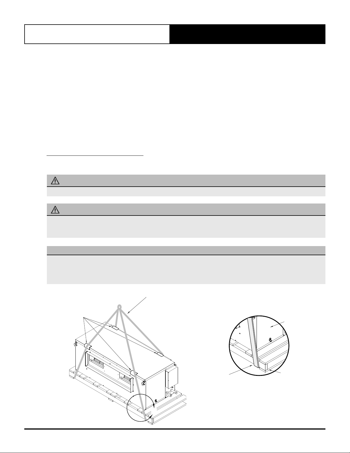
Lifting the Unit
The installation instructions provided, in Section 06, adhere to WH&S regulations for safe and secure lifting practices in
order to prevent physical injury.
Suggested lifting procedures are outlined in Section 06 as a reference guide to safely lift and transport the unit, however,
this does not over rule the industry WH&S practices.
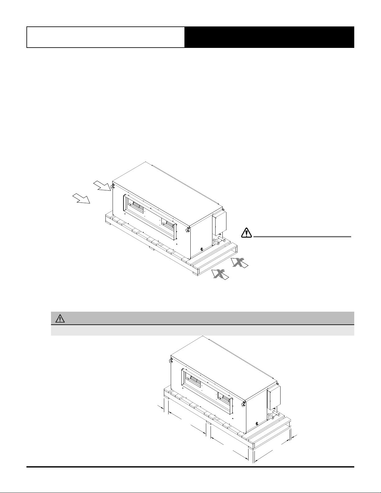
Location
This unit is intended for indoor installation only. It is highly recommended that this indoor unit and accessories, be
mounted in the roof cavity.
Mount the unit in a stable and rigid support wherein the weight is properly distributed, such as roof joist and rafters. Take
into consideration the minimum service access clearances provided in the unit drawings.
Locate the indoor unit away from the areas where noise is a critical factor. Use rubber mounting pad (not supplied) in
order to minimize the transfer of noise and vibration into building structures.
A hanging bracket assembly and rubber grommet (optional on other units) are also provided to secure the indoor unit
into the roof rafters. This configuration is most suitable for installations that require the unit to be rigidly secured up from
the roof joist.
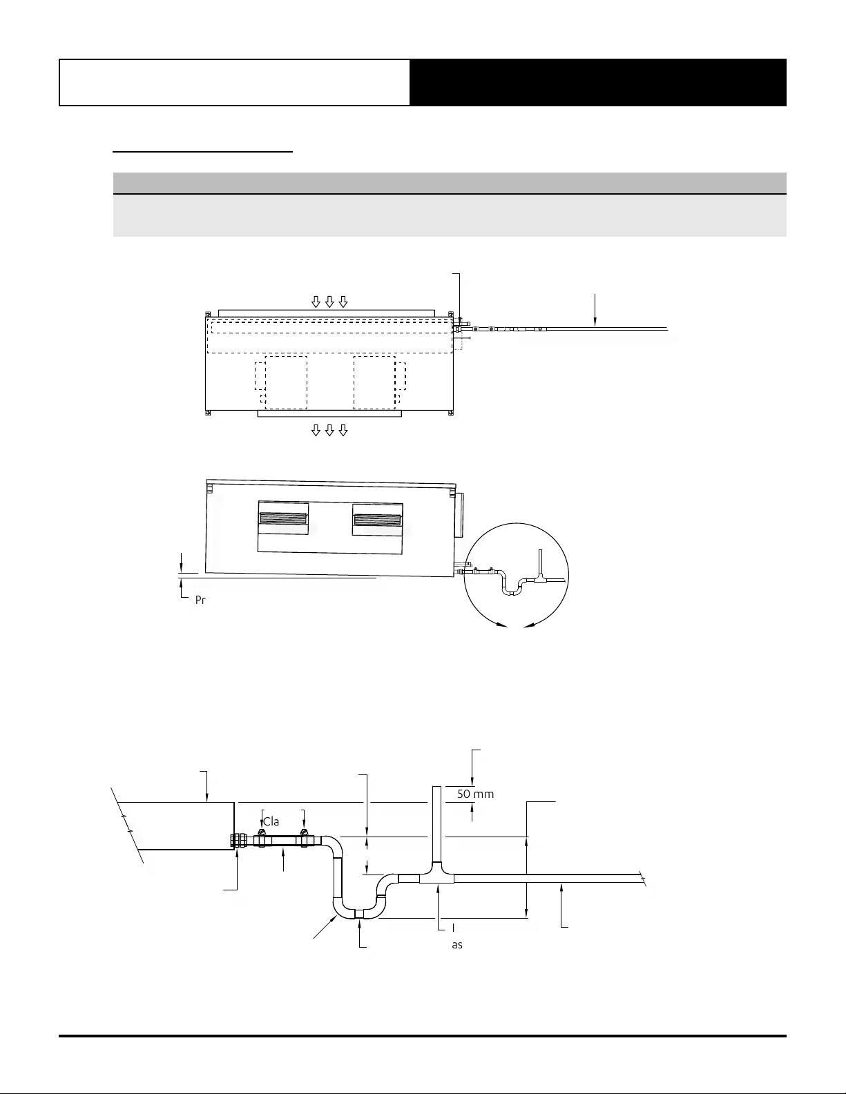
Condensate Drain
A drain kit (not supplied) is required for the condensate drain to be externally trapped from the indoor unit. Suggested
condensate drainage instructions are provided in Section 07 of this document for your reference.
ActronAir recommends the installation of a condensate safety tray and drain (not supplied).
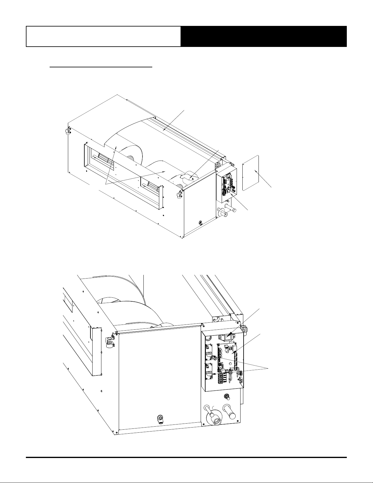
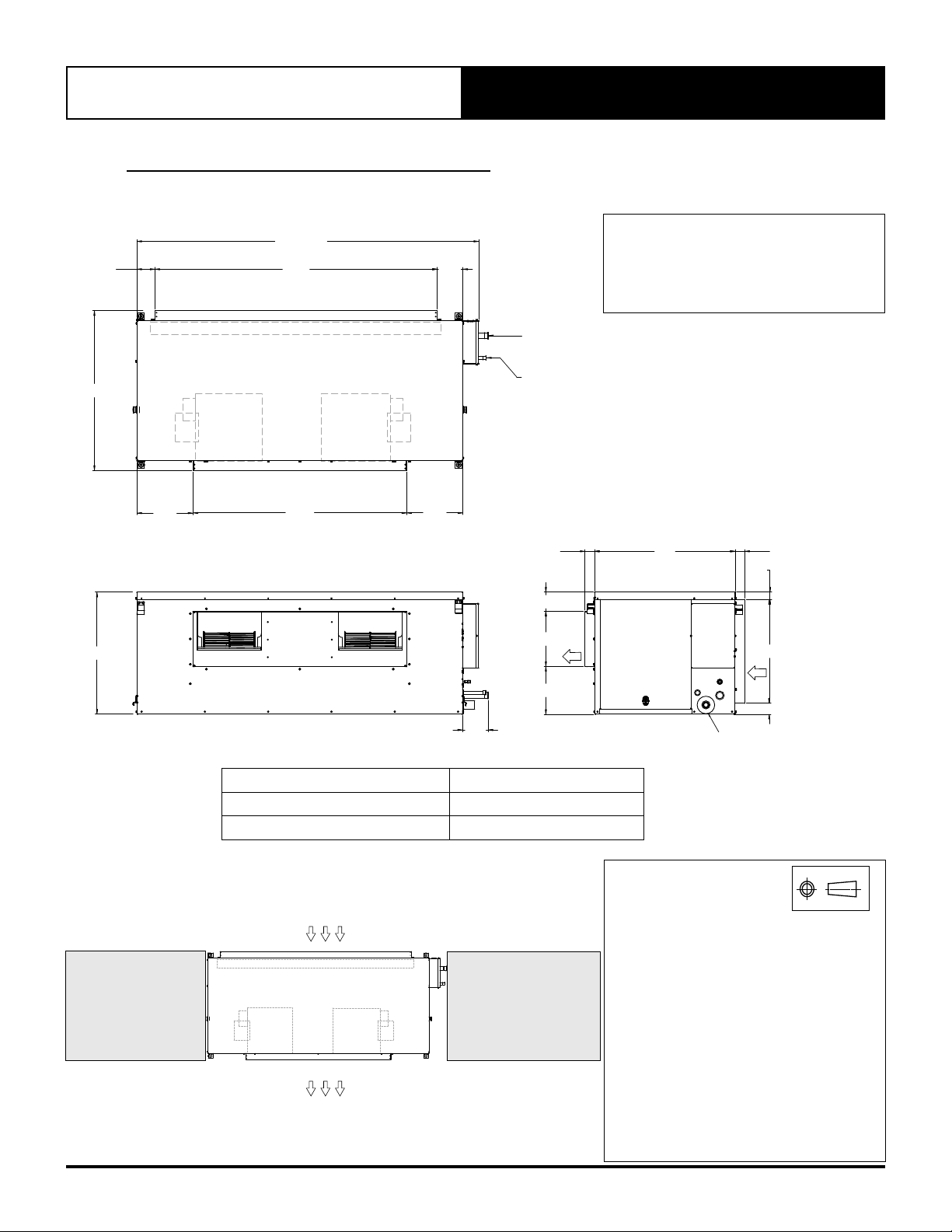
Supply Air and Return Air Duct
The indoor unit is supplied with a duct flange as standard in order to facilitate the system’s duct connection into the unit.
Supply and return air duct work must be adequately sized to meet the system’s air flow and static pressure requirements.
Refer to the unit drawing for supply air and return air duct dimensions, specific to your requirement.
NOTE
Fit a flexible duct connection in between the unit and the duct system, where noise and vibration is a critical consideration.
Return Air Filter
Return Air filters must be provided in the return air side of the unit to maintain the efficiency and prolong the operation
of the unit. These are also paramount to satisfy the requirement for a clean and hygienic room condition. Return Air
filters must be placed in an easily accessible location for service and maintenance.
NOTES
• Return Air filters are not supplied with the unit as individual air filtration requirements vary.
• Ensure that filters are cleaned / replaced regularly.