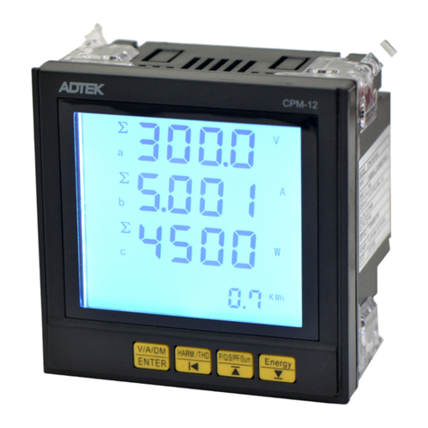
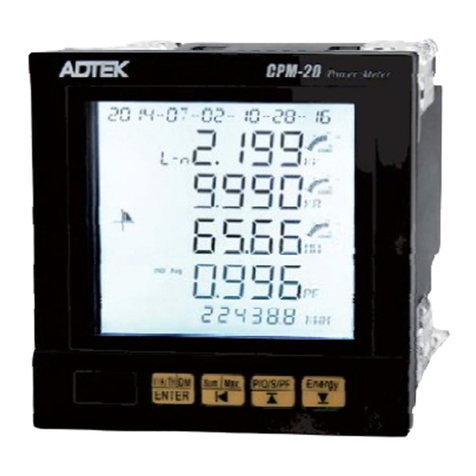
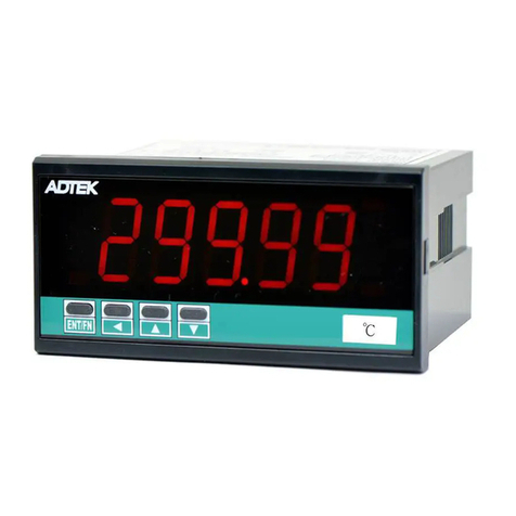
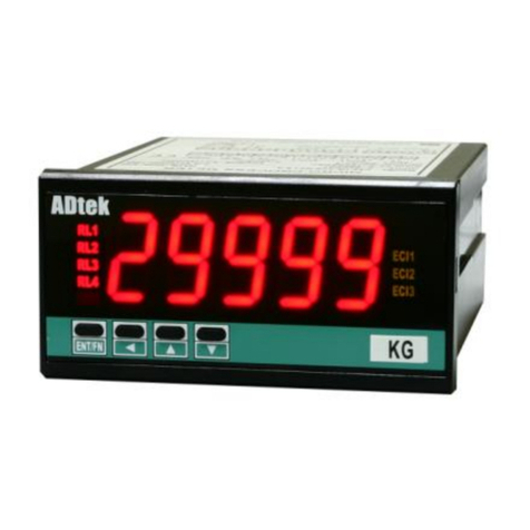
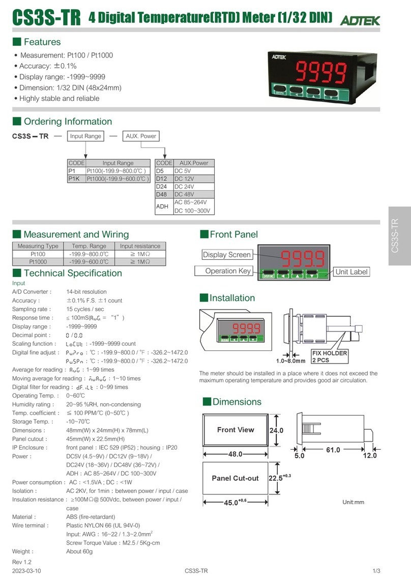
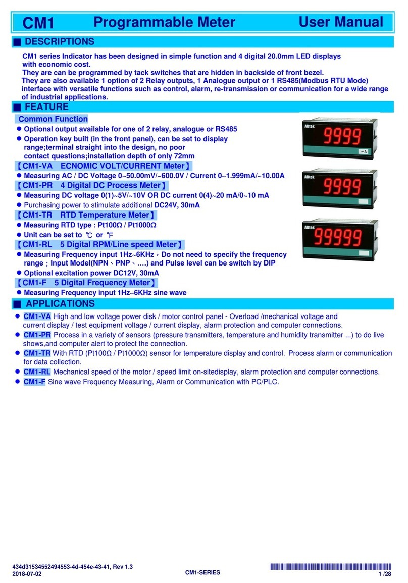
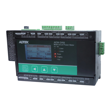
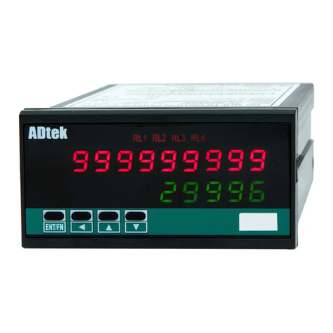
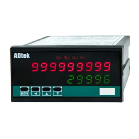
ADTEK CS1-SG User manual

CHANG SHUAN ELECTRONICS CO., LTD.
TEL:+886 2 29953100 FAX:+886 2 29953101
EMAIL: [email protected]
Website: www.adtek.com.tw

1 / 10 CS1-SERIES (V1.0) OPERATION MANUAL 2006-10-26
CS1-VA(V1.0) VOLT / CURRENT METERS
CS1-PR(V1.0) DC SIGNAL INDICATOR
CS1-SG(V1.0) STRAIN GAUGE INDICATOR
CS1-PM(V1.0) POTENTIOMETER INDICATOR
CS1-RS(V1.0) RESISTANCE INDICATOR
OPERATION
MANUAL
CS1-T(V1.0) TEMPERATURE INDICATOR
■ FEATURES
【CS1-VA VOLT / CURRENT METER】
¾Measuring Voltage 0~600V or Current 0~10A;DC / AC / TRMS
【CS1-PR DC SIGNAL INDICATOR】
¾Measuring DC 0~10V or 0(4)~20 mA in process
【CS1-SG STRAIN GAUGE INDICATOR】
¾Measuring Strain Gauge from 0~1.0/~2.0/~4.0 mV/V or 0~10.0/~20.0/~40.0
mV/V specify with excitation supply DC 5V or 10V, 30mA
¾Field calibration with strain gauge to meet the system requirement
【CS1-PM POTENTIOMETER INDICATOR】
¾Measuring Potentiometer 0.0Ω~2.0KΩ/ 0.0Ω~50 KΩ
¾Field calibration with potentiometer to meet the system requirement
【CS1-RS RESISTANCE INDICATOR】
¾Measuring Resistance(2-wired) 0~200.00Ω/2000.0Ω/20.000KΩ/200.00KΩ
¾Field calibration with potentiometer to meet the system requirement
【CS1-T TEMPERATURE INDICATOR】
¾Measuring Pt100Ω; T/C: K,J,E,T
FEATURES
● 1 relay, 1 Analogue output or RS 485 communication port can be
selected one in option
● Relay for Hi / Lo energized with Start Delay / Hysteresis / Energized &
De-energized Delay / Relay Energized Hold….. functions
● CE Approved
FUNCTIONS
■ DISPLAY FUNCTIONS ¾If the setting value is negative, it means the range
of under setting value will be 0; PV≤-Setting value,
the display will be 0;
EX:Low Cut is set for -0.01, if the display is ≤-0.01,
and all the display will be 0.
zDigital filter: seting range from 0(None)/1~99 times.
The digital filter can reduce the magnetic noise in field.
zDigital Fine Adjustment: seting range from
-19999~+29999 ;Users can get Fine Adjustment by
front key of the meter, and “Just Key In” the value
which user want to show in the current input signals.
■ RELAY FUNCTIONS
Front Key Function
The down key on front panel can be set rEL.Pv /
Pv.HLd / M.rSt / rY.rSt functions. When down key to
be pressed, the function customer selects 【dn.KEY】
in engineer level will be done .
zrEL.Pv: Relative present value
zPv.HLd: Present value hold
zM.rSt: Maximum and minimum memorize reset
zrY.rSt: Relay energized reset
Maximum and Minimum memorize:
The meter will keep update maximum and minimum
value in User Level during power on until manual reset
by front key.
Write to display by RS485 command
The display can be written by RS485 command. In past,
The meter nomorlly receive 4~20mA or 0~10V from AO
card or BCD card of PLC. We support a new solution by
RS485 writing in so that can be save cost and wiring
into PLC.
Low Cut / Digital Filter / Digital Fine Adjustment
zLow Cut: seting range from -5000~+5000 counts.
¾If the setting value is positive, it means the range of
absolute value will be 0; PV≤Setting value, the
display will be 0;
EX:Low Cut is set for 0.10, if the display is from
-0.10~+0.10, that will be 0.
Start Delay
Hysteresis: Settable range from 0~9999 Counts
Relay energized delay: Settable range from
0.1(second)~9(minutes)59.9(seconds);
Relay de-energized delay: Settable range from
0.1(second)~9(minutes)59.9(seconds)
Start Delay Energized
/
De-energized Delay
& Hysteresis
Start Dela
y
Time
Start Band
(
SB
)
Hi Settin
g
Rela
y
Ener
g
ized ON
Inhibit
Inhibit Hi Settin
g
Energized delay time
Rela
y
Ener
g
ized ON
H
y
steresis
De-energized
delay time
Relay energized mode Hi / Lo / Hi.HLd / Lo.HLd
zHi:Relay will energize when PV > Set-Point
zLo:Relay will energize when PV < Set-Point

2 / 10 CS1-SERIES (V1.0) OPERATION MANUAL 2006-10-26
■ ANALOGUE OUTPUT FUNCTIONS
zHi.HLd (Lo.HLd): When the PV Higher (or lower) than
set-point, the relay will be energized and latch until
manual reset by from key in【User Level】.
Hi o
r
Lo Relay Energized Hi(Lo) Energized Hold & Reset
Hi Settin
g
Hi Relay Energized ON
Lo Settin
g
Lo Relay Energized ON
Hi Settin
g
Hi.HLd(High Hold)
Rela
y
Ener
g
ized ON
Reset the relay Hold
by ECI or Front Key
ON
Level Trigger
SCALE Default:
A
i.Lo: 0%,
A
i.Hi: 100%; Lo.SC: 0.00, Hi.SC: 100.00
Change to
A
i.Lo: 0%,
A
i.Hi: 75%; Lo.SC: 0.00, Hi.SC: 199.99
0.00
199.99
100.00
0.
0
0%
100.00%50.00%
INPUT
75.00%
0.00% 100.00%50.00%
OUTPUT
199.99
100.00
0.00
Setted Scaling: Lo.SC: 0.00, Hi.SC: 199.99;
Desired Output: Ao.Lo: 50.00(PV),
A
o.Hi: 150.00(PV)
50.00
150.00
SCALE
FIELD CALIBRATION(This function is for CS1-SG, CS1-PM & CS1-RS)
In pass time, engineers have take a lot of time to adjust meters or converter to meet the structure of machinery zero
and span for the Load Cell and Potentiometer measuring. Now, our CS2-SG & CS2-PM support easlier process to
do it called “Field Calibration”.
zAdjust the structure of machinery to be “zero status”.
zEnter the right pass code of the meter to get into the Field Calibration Level.
zMove page to the CAL.Lo , and press ENT Key to stand by. Press ENT Key again to read the signal low of sensing
device. After it done, the page will change to CAL.Hi automatically. The low point will be the new zero.
zAdjust the structure of machinery to be “span status”.
zIn CAL.Hi page, press ENT Key to stand by. Press ENT Key again to read the signal high of sensing device. After it done,
the page will change to C.SEL automatically. The high point will be the new span.
¾Reading the signal will take few seconds.
¾Please check the setting of high scale Hi.SC and low scale Lo.SC again, after the “Field Calibration” has done.
zC.SEL(Calibration parameter selection): Field calibration don’t change the default calibration. So, after you do field
calibration, you can select default calibration if you want.
■ APPLICATIONS
Switch Boards
Motor Control Boards
Display Voltage or Amp for Mechanical Equipment
Machinery Control
Process Control Systems for pressure, level,….
sensing transducers
Automation System
Testing Instruments
AO
A
L
RS 485
RL1
CO
M
ENT/FN
◄
▲
▼
~
A
Measurin
g
Input
Coil of Transformer
Coil of Motor
RS 485 Modbus RTU Mode (up to 38400bps)
1 Relay Output:
Mode: High or Low Energized
Functions: Start delay / Energized &
De-energized delay / Hysteresis
Analo
g
Output 0~10V/0(4)~20mA
Display:
Mode: Measuring Value / Maximum Hold /
Minimum Hold / Reading value from
RS485 command
AL
RL1
CO
M
ENT/F
N
◄
▲
▼
~
A
RL1
CO
M
EN
◄
▲
▼
Hz
AL
Field Calibration(CS1=SG and CS1=PM only):
The meters can be calibrated for zero and span
with STRAIN GAUGE (POTENTIOMETER)
transducers in field.
■ FRONT PANEL ■ INSTALLATION
RL1
COM
ENT/F
N
?
?
?
Comm. status
Relay status
Indication
Operation Key Display screen
1.0~8.0 mm
FIX HOLDER:
72 mm(L) / W M3
R
COM
ENT/ FN
?
?
?
PANEL CU
T
-OUT:
92+0.2(W) x 44+0.2(H) mm

3 / 10 CS1-SERIES (V1.0) OPERATION MANUAL 2006-10-26
■ DIMENSIONS
96.0
48.0
92.0+0.2
44.0+0.2
PANEL CUT-OUT
FRONT VIEW
Unit: mm
8.0
12.0
60.0
Dimensions: 96mm x 48mm x 72mm
Panel Cutout: 93mm x 45mm (advise)
■ CONNECTION DIAGRAM
【CS1-VA VOLT / CURRENT METER】【CS1-PR PROCESS(DC) INDICATOR】
A3A1 A2 1 2 4 53 7 86 9 10
A
C230V
A
C115V
DC Power
A
UX. POWER
SIGNAL INPUT
FG
A
nalogue
out
p
ut
RS 485 port
A
B
Rela
y
b c a
Relay, Analogue
or RS485 can be
specified one only.
11 12 14 1513 16
SIGNAL INPUT
0~10V
0~20mA Excit.
Supply
DC24V
FG DC Power
A
C115V
A
UX. POWER
7 8 9 10
5 64
A
nalogue
out
p
ut
RS 485 port
A
B
Rela
y
b c a
【CS1-SG STRAIN GAUGE INDICATOR】【CS1-PM POTENTIOMETER INDICATOR】
mV/V
SIGNAL
INPUT
11 12 14 1513 16
10Vdc
Excit.
Supply
FG DC Power
A
C230V
A
C115V
A
UX. POWER
7 8 9 10
5 64
A
nalogue
out
p
ut
RS 485 port
A
B
Relay
b c a
POTENTIOMETER
11 12 14 1513 16
FG DC Power
A
C230V
A
C115V
A
UX. POWER
7 8 9 105 64
A
nalogue
out
p
ut
RS 485 port
A
B
Relay
b c a
■ ORDER INFORMATION
■ ORDERING INFORMATION
CS1−VA−
DC/AC/
TRMS
Input
Signal
−
Optional
Output
−
Aux.
Powered
CODE VOLT INPUT CODE CURRENT INPUT
CODE OPTIONAL O/P CODE AXU. POWER
D DC measuring D DC measuring N None A AC 115/230 V
A
AC measuring A AC measuring R1 1 Relay
T
TRMS measuring T TRMS
V1
0 ~ 199.99 mV A1 0 ~ 199.99 µA V 0(1) ~ 5 V /
0 ~ 10 V
V2 0 ~ 1.9999 V A2 0 ~ 1.9999 mA
V3 0 ~ 19.999 V A3 0 ~ 19.999 mA I 0 ~ 10mA
0(4)~20 mA
V4 0 ~ 199.99 V A4 0 ~ 199.99 mA 8 RS 485
V5
0 ~ 300.0 V A5 0 ~ 1.9999 A
V6
0 ~ 600.0 V A6 0 ~ 1.0000 A
VA
0~50 mV A7 0 ~ 5.000 A
Relay, Analogue Output
or RS485 Port can be
selected one only
VB
0~60 mV A8 0 ~ 10.000 A
VC
0~100 mV AO
Specify A input
VO
Specify V input
OPTION
■ ORDERING INFORMATION
CS1−PR−
Input
Signal
−
Optional
Output
−
Excit.
Supply
−
Aux.
Powered
CODE
INPUT RANGE CODE OPTIONAL O/P CODE EXCIT. SUPPLY CODE AXU. POWER
A1
0(4) ~ 20 mA N None N None A AC115/230V
V1 0 ~ 10 V R1 1 Relay E24 DC 24V
AV 0~10V/0(4)~20mA(all in one) EO
Optional
AO
Specify A input V 0(1) ~ 5 V
0 ~ 10 V
VO
Specify V input
I 0 ~ 10 mA
0(4)~20 mA
8
RS 485
Relay, Analogue Output
or RS485 Port can be
selected one only
OPTION
OPTION 5

4 / 10 CS1-SERIES (V1.0) OPERATION MANUAL 2006-10-26
■ ORDERING INFORMATION
CS1−SG−
Input
Signal
−
Optional
Output
−
Excitation
S
u
−
Aux.
Powered
CODE INPUT CODE INPUT CODE OPTIONAL O/P CODE EXCITATION CODE AXU. POWER
S1 1.0mV/V S8 10.0mV/V N None E05 DC 5V A AC 115/230 V
S2 2.0mV/V S9 20.0mV/V R1 1 Relay E10 DC 10V
S3 4.0mV/V SA 40.0mV/V EO Specify
SO Specify V 0(1) ~ 10 mA
0 ~ 10 V
I 0 ~ 10 mA
0(4) ~ 20 mA
8 RS 485
Relay, Analogue Output
or RS485 Port can be
selected one only
OPTION
■ ORDERING INFORMATION
CS1−PM−
Input
Signal
−
Optional
Output
−
Aux.
Powered
CODE INPUT RANGE CODE OPTIONAL O/P CODE AXU. POWER
P1
0~50Ω/~ 2.0 KΩN None A AC 115/230V
P2
0~50Ω/~ 100.0 KΩR1 1 Relay
PO
Specify input
V 0(1) ~ 5 V
0 ~ 10 V
I 0 ~ 10 mA
0/4 ~ 20 mA
8 RS 485
Relay, Analogue Output
or RS485 Port can be
selected one only
OPTION
■ ORDERING INFORMATION
CS1−RS−
Input
Signal
−
Optional
Output
−
Aux.
Powered
CODE INPUT RANGE CODE OPTIONAL O/P CODE AXU. POWER
R1
0.1Ω~ 200ΩN None A AC 115/230V
R2
0.1Ω~ 2000ΩR1 1 Relay
R3
0.1Ω~ 20.0KΩ
R4
0.1Ω~ 200.0KΩV 0(1) ~ 5 V
0 ~ 10 V
PO
Specify input
I 0 ~ 10 mA
0(4) ~ 20 mA
8 RS 485
Relay, Analogue Output
or RS485 Port one only
can be selected.
OPTION
■ ORDERING INFORMATION
CS1−T−
Input
Signal
−
Optional
Output
−
Aux.
Powered
CODE
INPUT RANGE CODE
INPUT RANGE CODE OPTIONAL O/P CODE AXU. POWER
P1 Pt100Ω-50.00~199.99 °C K1 Type K 0.0~1200.0 °C N None A AC 115/230V
P2 Pt100Ω-150.0~800.0 °C J1 Type J 0.0~750.0 °C R1 1 Relay
E1 Type E 0.0~1000.0 °C
T1 Type T 0.0~400.0 °C V 0(1) ~ 5 V
0 ~ 10 V
R1 T/C type R 400~1600 °C
S1 T/C type S 400~1600 °C I 0 ~ 10 mA
0(4) ~ 20 mA
B1 T/C type B 400~1800 °C 8 RS 485
Relay, Analogue Output
or RS485 Port can be
selected one only
OPTION
■ OPERATING STEPS:
STEP DESCRIPTION DISPLAY FLASH REMARK
BEFORE POWER ON, PLEASE CHECK THE SPECIFICATION AND
CONNECTION AGAIN.
SELF-DIAGNOSIS AND ERROR CODE:
: Display is positive-overflow (Signal is over display range) (Please check the input
signal)

5 / 10 CS1-SERIES (V1.0) OPERATION MANUAL 2006-10-26
: Display is negative-overflow (Singal is under display range) (Please check the input
signal)
: ADC is positive-overflow (Signal is higher than input 120%) (Please check the input
signal)
: ADC is negative-overflow (Signal is lower than input -120%) (Please check the input
signal)
/ : EEPROM occars error (Please send back to
manufactory for repaire)
/ : Calibrating Input Signal do not process (Please process Calibrating
Input Signal)
/ : Calibrating Input Signal error (Please check Calibrating
Input Signal)
/ : Calibrating Output Signal do not process (Please process Calibrating
Output Signal)
/ : Calibrating Output Signal error (Please check Calibrating
Output Signal)
*Please enter to Engineer Level to check and set the parameters when users start to install the meter
*KEY FUNCTIONS:
SHIFT: (1) In each Function Index Page, press this key about 1 second will return to the
Function Group.
(2) In Function Setting Page, press this key about 1 second will return to the
Function Index page.
(3) During Setting, press this key will move the bright digit (i.e. can be adjusted digit)
UP: (1) During number Setting, press this key can roll the digit up.
(2) In Function Setting Page, press this key can switch functions.
(3) In Function Index Page, press this key will back to the last Function Index Page.
DOWN: (1) During number Setting, press this key can roll the digit down.
(2) In Function Setting Page, press this key can switch functions.
(3) In Function Index Page, press this key will go to the next Function Index Page.
ENT ENTER: Press this key to confirm and save the setting.
¾In Engineer Level, the
screen will return to
Measuring Page after do
not press any key over 2
minutes, or press
for 1 second.
■ OPERATING DIAGRAM:
¾USER LEVEL
Power on
USER LEVEL
Press for 1 second can back to Measuring Page
Self-diagnosis 0
−
0
−
1
▲
▼
Pv: Present Value
If the display function has
been setted RS485, the
Measuring Page will show the
number what is from RS485
command. The reading will
move to this step for checking
0
−
4▲
▼
MAX:PV Maximum storage
Display the model
number
CS1.vA: (Volt/Current)
CS1.Pr: (10V/20mA)
CS1.SG: (Strain Gauge)
CS1.PM: (Potentiometer)
0
−
1
▲
▼
rY.1.SP.: Relay 1 Set-point
setting
(default:10000)
Settable Range: 0~29999
¾Press ENT to enter & setting
0
−
5▲
▼
M.rSt: Maximum & Minimum
storage reset
Selectable: YES / no
¾Press ENT to enter & select
Display the software
version
0
−
2
▲
▼
rY.rSt: Reset for energize
hold of Relay
Selectable: YES / no
¾Press ENT to enter & select
0
−
6▲
▼
CS1.Pr: The model number
vEr1.0: fameware version 1.0
ENT
MEASURING PAGE
Press 1sec.
Press 1sec.
0
−
3
▲
▼
Min:PV Minimum storage 0
−
1
▲
▼
Cyclic to first page
ENT
Enter the password to
get into Engineer Level
Y
ES
Correct
NO
Default=1000
ENGINEER LEVEL
INPUT GROUP

6 / 10 CS1-SERIES (V1.0) OPERATION MANUAL 2006-10-26
¾ENGINEER LEVEL – INPUT GROUP
ENT
MEASURING PAGE
ENGINEER LEVEL
In Function Index Page, press ENT to enter Function Setting Page for setting;
press over 1 second to return Function Group Page.
ENT
Pass code enter A
−
1
▲
▼
Pv.dP: Decimal Point of PV
(Default: 0);
Range: 0/ 0.0 / 0.00 / 0.000 /
0.0000
¾Press ENT to enter & setting
A
−
7
▲
▼
Lo.Cut: Low Cut to show “0”
(default: 0);
Settable: ±19999 counts
¾Press ENT to enter & setting
Y
ES
CHECK
NO
default=1000
A
−
2
▲
▼
Lo.SC: Low scale
(Default: 0);
Range: -19999~+29999
¾Press ENT to enter & setting
A
−
8
▲
▼
AvG: Average for PV
(default: 1time);
Settable:
1(no function)~99times
¾Press ENT to enter & setting
▲
▼
INPUT GROUP
Press EN
T
FN
Press 1sec.
A
−
3
▲
▼
Hi.SC: High scale
(Default: 199.99);
Range: -19999~+29999
¾Press ENT to enter & setting
A
−
9
▲
▼
d.FiLt: Digital filter
(default: 0);
Selectable:
0(no function)/1~99times
¾Press ENT to enter & setting
A
−
4
▲
▼
Pv.Zro: Fine Zero Adjustment
for PV display
(Default: 0);
Range: -19999~29999
¾Press ENT to enter & setting
A
−
1
0
A
−
5
▲
▼
Pv.SPn: Fine Span
Adjustment for PV display
(Default: 0);
Range: -19999~29999
¾Press ENT to enter & setting
▲
▼
dn.KEY: Down key function
(default: nonE);
選擇範圍: nonE / rEL.Pv /
Pv.HLd / M.rSt / rY.rSt
none(None): no function
rEL.Pv: Relative PV(∆PV)
Pv.HLd: PV hold
M.rSt: Reset for max./mini.
memorize
rY.rSt:Reset for Relay Lo/Hi
energized hold.
¾Press ENT to enter & setting
A
−
6
▲
▼
Z.S.CLr: Clear Fine Zero &
Span Adjustment for PV
display
(Default: nonE);
Range:nonE / Pv.Zro / Pv.SPn
/ botH
¾Press ENT to enter & setting
A
−
1
1
▲
▼
P.CodE: Pass Code for enter
Engineer Level
(default: 1000);
Selectable: 0000~9999
¾Press ENT to enter & setting
¾A
−
6
▲
▼
diPLY: Display Function
(default: Pv);
Selectable:
Pv / Mini.H / MAx.H / RS485
Pv: Present Value
Mini.H: Minimum. Hold
MAx.H: Maximum Hold
RS485: Writing to display
from RS485 command
¾Press ENT to enter & setting
A
−
1
2
▲
▼
F.LoCk: Function Level Lock
(default: nonE);
Selectable: nonE / USEr /
EnG / ALL
none: No lock
USEr: User Level lock
EnG: Engineer Level lock
ALL: All Level lock
¾Press ENT to enter & setting
A
−
1
▲
▼
Cyclic to first page

7 / 10 CS1-SERIES (V1.0) OPERATION MANUAL 2006-10-26
¾ENGINEER LEVEL --- RELAY GROUP, ANALOGUE OUTPUT, RS485 GROUP
(The groups will be hidden, if the meter without optional function)
ENGINEER LEVEL
In Function Index Page, press ENT to enter Function Setting Page for setting;
press over 1 second to return Function Group Page.
▲
▼
RELAY GROUP
Press EN
T
FN
Press 1sec.
B
−
1
▲
▼
rY.Sb: Start band for Relay
energized
(default: 0);
Settable: 0~9999 counts
¾Press ENT to enter & setting
B
−
4
▲
▼
rY1.HY.: Relay 1 Hysteresis
(default: 0);
Settable: 0~5000 counts
¾Press ENT to enter & setting
B
−
2
▲
▼
rY.Sd: Start delay time for
Relay energized
(default: 0:00.0);
Settable: 0:00.0~9(m):59.9(s)
¾Press ENT to enter & setting
B
−
5
▲
▼
rY1.rd: Relay 1 energized
delay time
(default: 0:00.0);
Settable: 0:00.0~9(m):59.9(s)
¾Press ENT to enter & setting
B
−
3
B
−
6
▲
▼
rY1.Fd: Relay 1 de-energized
delay time
(default: 0:00.0);
Settable: 0:00.0~9(m):59.9(s)
¾Press ENT to enter & setting
▲
▼
rY1.Md: Relay 1 energized
mode
(default: Hi);
Selectable:
oFF / Lo / Hi/ Lo.HLd / Hi.HLd
/ do
oFF:Turn off the Relay
Lo: Low Level Energized; The
relay energized when PV
<Setpoint.
Hi: High Level Energized; The
relay energized when PV>
Setpoint
Lo.HLd: Low Level energized
hold; When the PV lower
than set-point, the relay will
be energized and hold until
manual reset by from key in
User Level or E.C.I.
Hi.HLd: High Level energized
hold; When the PV higher
than set-point, the relay will
be energized and hold until
manual reset by from key in
User Level or E.C.I.
do(Digital Outptu):Relay
energized by RS485
command
¾Press ENT to enter & setting
B
−
1
▲
▼
Cyclic to first page
ENGINEER LEVEL
In Function Index Page, press ENT to enter Function Setting Page for setting;
press over 1 second to return Function Group Page.
▲
▼
ANALOGUE
OUTPUT GROUP
Press EN
T
FN
Press 1sec.
D
−
1
D
−
5
▲
▼
Ao.SPn: Fine Span
Adjustment for Analog High
Output
(default: 0);
Settable: -19999~29999
¾Press ENT to enter & setting
▲
▼
Ao.Typ: Analogue Output
type selection
(default: A.4~20);
Settable:
v.0-10 (0~10V) / v. 0~5(0~5V) /
v.1-5(1~5V) / A.0-20(0~20mA)
/ A.4-20(4~20mA) /
A.0-10(0-10mA)
¾Press ENT to enter & setting
D
−
2
▲
▼
Ao.LS: Analogue Low Output
relative Low Scale
(default: according to Lo.SC);
Settable: -19999~19999
¾Press ENT to enter & setting
D
−
6
D
−
3
▲
▼
A
o.HS: Analogue High Output
relative High Scale
(default: according to Hi.SC);
Settable: -19999~29999
¾Press ENT to enter & setting
▲
▼
Z.S.CLr: Zero & Span Clear
for Adjustment
(default: nonE);
Settable: nonE / Ao.Zro /
Ao.SPn / both
nonE: No clear
Ao.Zro: Clear Zero Adjustment
Ao.SPn: Clear Span
Adjustment
both: Clear Zero and Span
Adjustment
¾Press ENT to enter & setting
D
−
4
▲
▼
Ao.Zro: Fine Zero Adjustment
for Analog Low Output
(default: 0);
Settable: -19999~29999
¾Press ENT to enter & setting
D
−
1
▲
▼
Cyclic to first page

8 / 10 CS1-SERIES (V1.0) OPERATION MANUAL 2006-10-26
ENGINEER LEVEL
In Function Index Page, press ENT to enter Function Setting Page for setting;
press over 1 second to return Function Group Page.
▲
▼
RS485 GROUP
Press EN
T
FN
Press 1sec.
E
−
1
▲
▼
Adres: Device number of the
meter
(default: 1);
Settable: 1~255
¾Press ENT to enter & setting
E
−
3
▲
▼
PritY: Parity
(default: n.Stb.2);
Settable: n.Stb.1 (None, 1 stop
bit) / n.Stb.2 (None, 2 stop bits)
/ odd / EvEn (Even)
E
−
2
▲
▼
baud: Baud rate
(default: 9600);
Settable: 1200 / 2400 / 4800 /
9600 / 19200 / 38400
¾Press ENT to enter & setting
E
−
1
▲
▼
Cyclic to first page
▲
▼
Cyclic to Input
Group
¾FIELD CALIBRATION LEVEL【THIS FUNCTION FOR CS1-SG , CS1-PM & CS1-RS】
ENT
& ▲
▼
F
−
1
▲
▼
CAL.Lo: Field Calibration Low
¾Press ENT Key to stand by
¾Press ENT Key again to read
the signal low of sensing
device
Y
ES
CHECK
NO
default=2000
F
−
2
▲
▼
CAL.Hi: Field Calibration High
¾Press ENT Key to stand by
¾Press ENT Key again to read
the signal high of sensing
device
F
−
3
▲
▼
C.SELi: Calibration parameter
selection is Field Cal. Or
default Cal.
¾Press ENT to enter & select
((default: dEFLd);
Selectable: dEFLd / FiELd
■ RS485 ModBus RTU Mode
1. Function 03H (Read Holding Registers)
Request Data Frame; EX: Read the data of display value(0000H starts from 1 Word)
SLAVE
Address
FUNCTION
Starting
Address Hi
Starting
Address Lo
No. of Word
Hi
No. of Word
Lo
CRC
Lo
CRC
Hi
01H 03H 00H 00H 00H 01H 84H 0AH
Response Data Frame; EX: The response value is ”0”
SLAVE
Address
FUNCTION Byte
count
Data
Hi
Data
Lo
CRC
Lo
CRC
Hi
01H 03H 02H 00H 00H B8H 44H
Request Data Frame (EX: Continue to request the data of 10 points)
SLAVE
Address
FUNCTION
Starting
Address Hi
Starting
Address Lo
No. of Word
Hi
No. of Word
Lo
CRC
Lo
CRC
Hi
01H 03H 00H 00H 00H 0AH C5H CDH
Response Data Frame
SLAVE
Address
FUNCTION Byte
count
Data(1)
Hi
Data(1)
Lo
……Data(10)
Hi
Data(10)
Lo
CRC
Lo
CRC
Hi
01H 03H 14H 00H 00H … … 01H 00H -- --

9 / 10 CS1-SERIES (V1.0) OPERATION MANUAL 2006-10-26
2. Writing Command by Function 06H (Preset Single Register)
Request Data Frame
SLAVE
Address
FUNCTION
Code
Starting
Address Hi
Starting
Address Lo
Preset
DATA Hi
Preset
DATA Lo
CRC
Lo
CRC
Hi
01H 06H 00H 00H 00H 02H 08H 0BH
Response Data Frame
SLAVE
Address
FUNCTION
Code
Starting
Address Hi
Starting
Address Lo
Preset
DATA Hi
Preset
DATA Lo
CRC
Lo
CRC
Hi
01H 06H 00H 00H 00H 02H 08H 0BH
■ ADDRESS TABLE **Address numbers are Hexadecimal
¾User Level
Name Address Range Explain Initial Write/Read Note
PV 0000h -19999~29999 Present Value R
PV.HD 0001h PV Hold R
0002h -19999~29999 The Minimum of PV R
0003h -19999~29999 The Maximum of PV R
SYSTEM
STATUS
0004h SYSTEM STATUS
bit0=1 EEP fail;
bit1=1 Input calibration fail;
bit2=1 Input calibration NG;
bit3=1 Analogue Output calibration fail;
bit4=1 Analogue Output calibration NG
00h R
0005h 0~1 Reset Maximum & Minimum Value
0:No 1:Yes
00h R/W
0006h -19999~29999 PV showing from RS485 command(data) 00h R/W
¾Engineer Level
【Input Group】
Name Address Range Explain Initial Write/Read Note
RESERVED No use unless CS1-PR
0007h 0~5 The address is for CS1-PR only
Analogue Input Type
0: 0~10V 1: 0~5V 2: 1~5V
3: 0~20mA 4:4~20mA 5:0~10mA
0008h 0~4 PV Decimal Point
0: 00000 1: 0000.0 2: 000.00 3: 00.000
4: 0.0000
00h R/W
0009h -19999~29999 Low Scale 0 R/W
000Ah -19999~29999 High Scale 19999 R/W
000Bh -19999~29999 PV ZERO 0 R/W
000Ch -19999~29999 PV SPAN 0 R/W
000Dh 0~3 The clear of PV_ZERO and PV_SPAN
0: None 1: PV_ZERO 2: PV_SPAN
3: Both
00h R/W
000Eh 0~3 Display Mode
0:PV 1: Minimum Hold 2: Maximum Hold
3: RS485
00h R/W
000Fh -19999~19999 Low Cut 0 R/W
0010h 1~99
Average 5 R/W
0011h 0~99
Digital Filter 0 R/W
0012h 0000~9999
Pass Code 1000 R/W
0013h 0~3 Function Lock
0: none 1: User Level 2: Engineer Level
3: All
00h R/W

10 / 10 CS1-SERIES (V1.0) OPERATION MANUAL 2006-10-26
【RS485 Group】
Name Address Range Explain Initial Write/Read Note
0014h 1~255 RS485 address 1 R/W
0015h 0~5 RS485 baud rate
0:1200 1:2400 2:4800 3:9600 4:19200
5:38400
03h R/W
0016h 0~3 RS485 parity
0: n-8-1 1:n-8-2, 2: odd, 3: even,
01h R/W
This manual suits for next models
5
Table of contents
Other ADTEK Measuring Instrument manuals
Popular Measuring Instrument manuals by other brands
LumaSense technologies
LumaSense technologies IGAR 12-LO manual
Gossen MetraWatt
Gossen MetraWatt DIGISKY operating instructions
Crompton
Crompton SL1-01 instructions

METREL
METREL Instaltest 61557 MI 2087 instruction manual
Vibra
Vibra HT CEN Series Operation manual
E Instruments
E Instruments E8500 Plus instruction & operation manual
