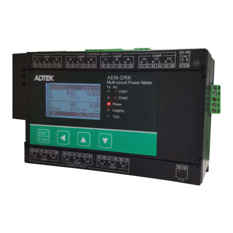
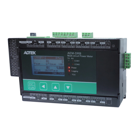
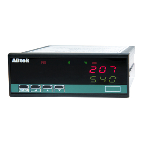
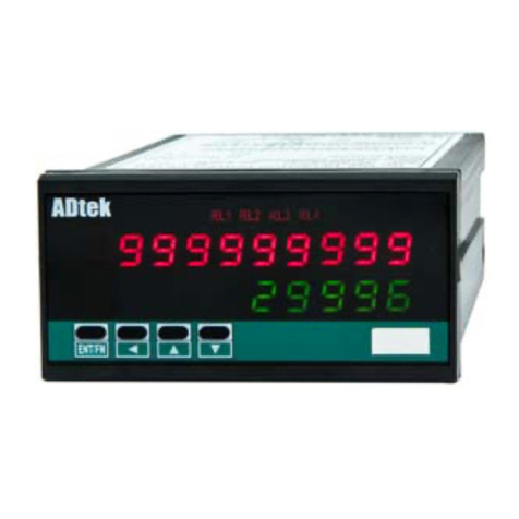
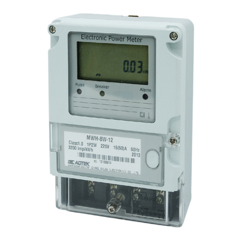
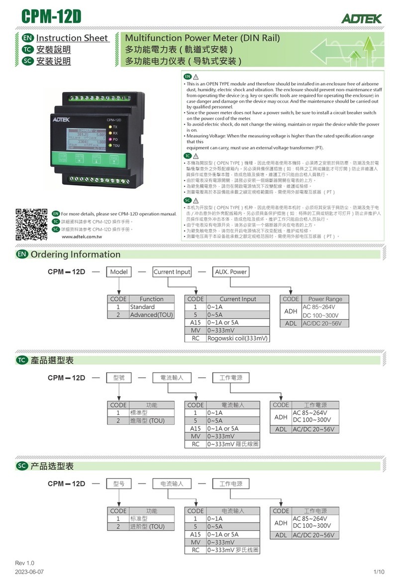
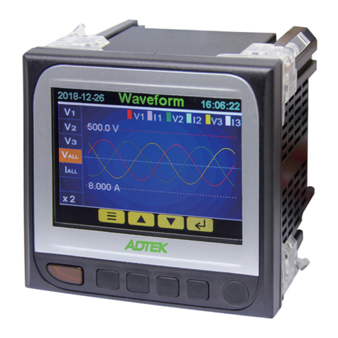
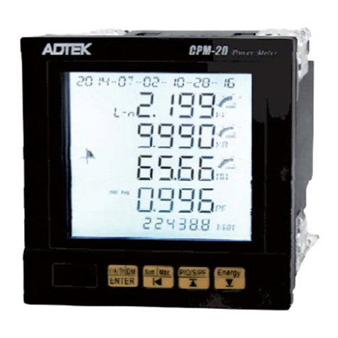
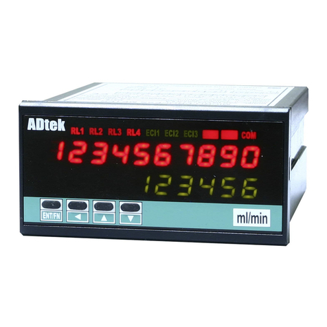
ADTEK MWH-10A User manual

MWH-10A
Operation manual
4d5748313041-4d-454e-53-41 Ver1 0,.
-2018 09-01
*4d5748313041-4d-454e-53-41*

1
FEATURE
Input 1P2W,1P3W,3P3W,3P4W Unbalanced load system's active power, reactive power,
apparent power and electric energy (Watts-Hr) etc parameters.
Dual display, 10 digits Watts-Hr,lower row 4 2/3 digits Watts.
1 set relay(SPDT) output, having relay function : Hi / Lo / Hi Hold / Lo Hold / OFF; further
advance function , start delay, hysteresis, time delay, reset delay etc
1 analogues output same as relay setting parameters.
Output range: Current 0~10mA / 0~20 mA / 4~20 mA (Default 4-20mA)
Output range: Voltage 0~5V / 1~5 V / 0~10 V / 0~±5 V (Default 0-10V)
Option pulse and RS 485 communication output.
ENT/FN
AWHPLS
COM
WMK
KV VRL1
ENT/FN
AWH
COM
WMK
KV VRL1
Wa -tt hr
LED display
Relay
Control button
Active power (Watt)
LED display
Low row:
Watt display
Voltage unit
KV V,LED
Up row:
Watt-hr
Rs485 Status
Front panel and button
output LED
MWH-10-A Operation manual
4Control buttonEnter / Shift / Up / Down
Up key: Increase /back to previous
Down key: Decrease /to next
Shift key: Change decimal/back to previous
or escape setting
Enter/Fun key: Enter setting/save changes and
enter next parameters
COM
RL1
Display digits
Operation button
LED status
RS 485 Com.: 1 rectangular orange LED,when
R 485 send/receive data,LEDS
blink´blink faster mean data
transfer
Relay: 1 rectangular red LED,LED light
when relay energized
KV
WH
LED Unit
Voltage unit LED rectangular red LED indicate KV: 2
or V ,on when display select V-A
Watt unit LED Rectangular green LED , on when: 3
display select KWH, automatic switch
KW or MW units
Watt-hr LED rectangular red LED, on when select: 1
KWH display , only display WH, K/M
unit follow Watt.
V
M
K
W
PV value: 4 2/3 digits; 0.28”(0.71cm)green LED
Accumulative value 10 digits; 0.28”(0.71cm):
red LED

2
Output wiring
AK AL
Please check if the voltage is correct and connect to the right terminal number when wiring
CL
AK AL CK
CL
BK
AK AL BL CK
Output
AO RS485
Output
Output
AO RS485
Output
If no PT please direct input
to terminal
source
Load
If no PT please direct input
to terminal
Output
AO RS485
Output
If no PT please direct input
to terminal
source
Load
source
Load
CL
BK
AK AL BL CK
Output
AO RS485
Output
If no PT please direct input
to terminal
source
Load
A1~A16: 20A/600Vac, M3.5, 22~12AWG;
13Kg-cm
:10A 300Vac, M2.6, 22~16AWG,
:5Kg-cm
7.0mm max
7.0mm max
2.0mm max
Wire terminal
Terminal:
Max Torque:
Output Terminal
Max Torque
Please use flat Pin
78 9 10
L
N
G
L
N
G
1A
AUX
Fuse
Transformer filter
Installation
Dimension
This meter is installed does not exceed the maximum
operating temperature and humidity environment.
Unit: mm
Size 96mm x 48mm x 120mm:
48.0
Front
Cut size 4.05+0.2
92.0+0.2
96.0 100.0
8.0 12.0
Cut size:29 m m x 4 5 m m
+0.2 +0.2
1.0~8.0 mm
FIX HOLDER:
104 mm(L) / W M3
PANEL CUT-OUT:
92+0.2(W) x 45+0.2(H) mm
ENT/
FN
?
RL
1
RL
2
EC
I1
EC
I2
k
w
h
M
K
k
w
W
?
W
H
1Phase 3 wire
1Phase 2 wire 3Phase 3wire 2CT (Unbalanced)
3Phase 4wire 3CT (Unbalanced)
Aux.Power Aux.Power
Aux.Power
Aux.Power

3
Output wiring Please check if the voltage is correct and connect to the right terminal number when wiring
37.0
L
K
K
L
K
L
63.6
41.0 Ø13.0(D)
L
K
K
L
K
L
Fixing by
Cable Tie
L
K
K
L
K
L
Max Load 50A
Connect to
Current input
of Meter
Optional modules: high-precision CT module – YMWH-CT10A – 0.1class
Do not ground the use of CT module - YMWH-CT10A
With YMWH-CT10A(CT ) 1P2WModule
50Amp CT Module (YMWH -CT10A)
Note Do not ground:
KL
L
N
SOURCE
AK AL
If no (PT)
,
please connect
to according terminals
LOAD
Aux.Power
UA UN
RS485
Port
Analogue
Output
With YMWH-CT10A(CT ) 1P3WModule
K L
N
L2
SOURCE
L1
AK AL CK CL
KL
50Amp CT Module(YMWH -CT10A)
Note Do not ground:
,
If no (PT) please connect
to according terminals
LOAD
UC
UA UN
RS485
Output
Analogue
Output
With YMWH-CT10A(CT ) 3P3WModule
KL
B
C
SOURCE
A
AK AL CK CL
KL
50Amp CT Module
(YMWH-CT10A)
Note Do not ground:
If no (PT)
,please connect
to according terminals
LOAD
UCUA UNUB
BK BL RS485
Output
Analogue
Output
With YMWH-CT10A(CT ) 3P4WModule
B
C
N
A
AK
UB UCUA UN
AL BK BL CK CL
KLKLKL
If no (PT)
,please connect
to according terminals
LOAD
50Amp CTModule(YMWH-CT10A)
Note Do not ground:
SOURCE
RS485
Output
Analogue
Output
1Phase 2 wire 1Phase 3 wire
3Phase 3wire 2CT (Unbalanced) 3Phase 4wire 3CT (Unbalanced)
Aux.Power
Aux.Power Aux.Power

4
CSM-
Voltage/Current
16
16
B
A
16
B
A
Analogue output
Please earth isolation net to maintain signal quality
Wire distance: 1200M
:
120~300ohm/0.25W
(typical: 150ohm)
End terminal ohm
Output mode: Selectable
within parameters setting,
voltage or current output need
to short J2 & J3 on output PCB
module.
Analogue + RS485
Voltage/Current
30V/60mA
()c()c()e()e
5 6 7
Pulse or relay output
Due to limitation on number of terminal , pulse and relay
output is having same terminal, choose either one
Open collector:(OPC1)
Max load
1A/230V 3A/115V,
COM NC
5 6 7
NO
Relay Pulse output: OPR1()
Contact: Action frequency
less than 30HZ
1A/230V 3A/115V,
COM NC
5 6 7
NO
Contact:
Alarm Relay output:(OR1)
RS Com485 .

5
■Operation flow chart:
Hold 1S
Check wiring
before power up
******
******
3p4W1
mwh-10a
ver1.0
Hold escape to measuring page
rYrst
Reset relay
0-2
Relay 1.1 setting
point
rLsp
0-1
veR10
wh-10a
Version Model
0-3
Self test
(LED all on) Wire type
Model
Software
To relay setting
group
rs485
group
ao
RELAY
GROUP
group
relay
enter
Pcode
NO
YES
ENT
P
ENT
P1S back
10)0
)0
ANALOGUE
OUTPUT
GROUP
RS485
GROUP
INPUT
GROUP
group
input
Password
P.code
Correct
Default:1000
PV value
W/H
W
Engineer level
INPUT
GROUP
group
input
cTsec
%000
A-5
tLrst
0000
A-9
1S back
ENT
P
Uunit
v
A-1
Primary PT unit:/VKV
pTpri
30)0
A-2
Primary PT voltage
50 100V~ KV
pTsec
30)0
A-3
Secondary PTvoltage
50 500V~ V
cTpri
5)0
A-4
Primary CT current
Secondary CT
current
avg-p
5
A-6
Active power
average
Reset Watt-Hr/Var-Hr
Pcode
1000
A-10
Change P. code
Flocy
none
A-11
Function lock
Press sec escape to measuring page1
)0)0
rl-fd
Relay delay de-
energize
B-8
)0)0
rl-sd
Relay start
delay
B-5
)00
rl-sb
Relay start
band
B-4
3)00
rl-sp
B-2
Relay set
point
hi
rl-md
Relay mode
B-1
RELAY
GROUP
group
relay basic
prog
Program:
BASIC back to B-1/
ADUNC down to B-8
B-3
)00
rl-hy
Relay
hysteris
B-6
)0)0
rl-rd
Relay delay
energize
B-7
1S back
ENT
P
Press 1 sec escape to measuring page
group
pulse
PULSE
GROUP
No optional Relay ouput ,
only show out Version Mode
w-div
off
A-7
Watt high-resolution:
OFF:0(Normal)
ON:1(High)
lOcut
)2
A-8
Low Cut:
0.0~100.0%

6
no
rYrst
0-2
veR10
wh10a
0-3
10000
rl-sp
0-1
Press 1Sec
User Level
■Operating Steps
Power on
Check the wiring
******
******
Self test
LED all on
mwh-10-a
ver1.0
Into the relay function menu
No need to set
Back to 0-1
There is no relay functions
Will only display version
and model
Parameters Display Setting Operation
Wiring Model
Version
Relay funtion
setting
Relay value range:
-19999 29999~
Enter
DecreaseIncrease
Shift
Press values blink press change value or selection,&
when done press to next setting or hold 1 sec
to previous selection list.
Enter
DecreaseIncrease
Shift
Press values blink press change value or selection,&
when done press to next setting or hold 1 sec
to previous selection list.
Reset relay
function Select:
yes no/
Version
Model View only
Press sec escape to begining page.1
group
ao
ANALOGUE
OUTPUT
GROUP
1S back
ENT
P
A4-20
aOtp
Analogue
output type and
range
C-1
)00
aOls
Analogue output
low-scale
C-2
)00
aOhs
Analogue output
hi-scale
C-3
0
aOzo
Analogue output
low fine tunning
C-4
0
aOsn
Analogue
output Hi fine
tunning
C-5
zSclr
Reset fine tunning:
none
C-6
11)00
aOlt
Output limit
C-7
group
pulse
PULSE
GROUP
plSdu
1
plShi
0
1S back
ENT
PE-1
Pulse/Count High-potential
output time
E-2
Press sec escape to measuring page1
RELAY / PULSE output of the outputs can
only choose a functional output
EX: Select PULSE output and then RELAY
function no output and vice versa
prity
Modbus paraity:
n.stb.1/n.stb.2/odd/e
ven
NstB2
D-3
9600
baud
Modbus baud rate:
1200/2400/4800/9600/
19200/38400
D-2
1
adres
Address:
1~255
D-1
group
rs485
RS485
GROUP
1S back
ENT
P
Press sec escape to measuring page1

7
cTsec
%000
A-5
cTpri
5)0
A-4
pTsec
30)0
A-3
pTpri
30)0
A-2
Uunit
v
A-1
group
INPUT
GROUP
input
ENT
Pass word
enter
Pcode
Password correct
NO
YES
ENT
P
22)0 10)0
)0
W
ENT
P
Engineer level
■Operating Steps
Measurement
Display
group
INPUT
GROUP
input
ENT
INPUT
GROUP
Display
Range : /vkv
※Please note that this setting is the choice of the
corresponding primary voltage units. For example, if
Vunit kv, while this pTpri set to 45) 0, then the set
primary voltage for 450.0KV.。
group
RELAY
GROUP
relay
ENT
group
RS485
GROUP
rs485
ENT
group
ANALOGUE
OUTPUT
GROUP
ao
ENT
P1s Back P1s Back P1s Back
Parameters Display Setting Operation
AV
Default 1000:
Enter
DecreaseIncrease
Shift
Primary PT
voltage
unit V.Unit:
Press values blink press change value or selection,, &
when done press secto next setting or hold 1.
to previous selection list
V / KV
Default :V
Primary voltage
setting range
Setting range:
50 100.0V .00KV~
Default:300 0.
Secondary voltage
setting range
Setting range:
50 500.0V~ .0V
Default:300 0.
Primary CT
setting range
(VIEW ONLY)
Default:50.00
Secondary CT
setting range
Setting range:
1.0A 2 .9A~ 999
Default:5 000.
Press values blink press change value or selection,, &
when done press secto next setting or hold 1.
to previous selection list
Press values blink press change value or selection,, &
when done press secto next setting or hold 1.
to previous selection list
Enter
DecreaseIncrease
Shift
ENT
group
PULSE
GROUP
pulse
P1s Back
RELAY / PULSE output of the outputs can only
choose a functional output
EX: Select PULSE output and then RELAY
function no output and vice versa
P1s Back
P1s Back
PPPPP
P

8
Flocy
none
A-11
Pcode
1000
A-10
tLrst
0000
A-9
avg-p
5
A-6
※R 485 Key in to resetS0。
Engineer level
■Operating Steps
Active power
average value
setting range
Setting range:
2~99
Reset watt-
hr/var-hr to zero
Password:
0~9999
Change
parameters level
password
Password:
0000~9999
Function lock select:
NONE/USER/ENG/ALL
Press values blink press change value or selection,, &
when done press secto next setting or hold 1.
to previous selection list
Enter
DecreaseIncrease
Shift
Enter
DecreaseIncrease
Shift
Enter
DecreaseIncrease
Shift
Press values blink press change value or selection,, &
when done press secto next setting or hold 1.
to previous selection list
Enter
DecreaseIncrease
Shift
Default:5
none( ): ,None No function lock user can enter and change
setting
user(): ,User Level User level lock can view setting cant
change parameters value
eng(Programming Level): Parameters setting lock ,can view
setting cant change parameters value
all(All Level): All level lock,can view setting cant change
parameters value
Enter
DecreaseIncrease
Shift
Return to -1A
※System may have interference or signal unstable
sometimes, causing display unstable: This function help
to decrease rapid change on the display. Increasing
average value make display more stable,
Parameters Display Setting Operation
Press 1 sec to measuring page
Engineer level ( 485 )RS Output
prity
NstB2
D-3
baud
9600
D-2
adres
1
D-1
NstB1(. .1):n Stb None, 1 stop bit
NstB2(. .2):n Stb None, 2 stop bit
odd():odd odd
even():EvEn Even
Back to D-1
group
RS485
GROUP
rs485
ENT
RS485
GROUP
Display
Press 1 sec to []rs485 group
Default:1
Default:n.stb.2
Parameters Display Setting Operation
Press values blink press change value or selection,, &
when done press secto next setting or hold 1.
to previous selection list
Enter
DecreaseIncrease
Shift
Setting range:
1~255
Address setting
Setting range:
1200/2400/4800/9600/
19200/38400
Modbus Baud rate
Press values blink press change value or selection,, &
when done press secto next setting or hold 1.
to previous selection list
Modbus pairty bit Setting range:
n.stb.1/n.stb.2/odd/even Enter
Cycle
Press 1 sec to measuring page
Default:NONE
Default:1000
Default:9600
Low Cut Setting range:
0.0~100.0%
Default:0.2
lOcut
)2
A-8
m-div
off
A-7 Watt high-
resolution
Setting range:
OFF:0(Normal)
ON:1(High)
Default:OFF
Press values blink press change value or selection,, &
when done press secto next setting or hold 1.
to previous selection list
Enter
DecreaseIncrease
Shift
Press values blink press change value or selection,, &
when done press secto next setting or hold 1.
to previous selection list
Enter
DecreaseIncrease
Shift
P1s Back
P

9
adunc
prog
B-3
rl-sp
3)00
B-2
rl-md
hi
B-1
Engineer level()Raely Output
■Operating Steps
Enter
DecreaseIncrease
Shift
Relay mode Setting type:
LO HI LO.HLD HI.HLD// / /
/OFF
lo:PV Setpoint relay energized<, 。
hi:PV Setpoint relay energized>, 。
lo.hld:Display Setpoint relay energized<, ,
and hold energized status。
hi.hld:Display Setpoint relay energized>, ,
and hold energized status。
off:Close relay function when relay is off,
,relay remain open, LED will not light。
Press values blink press change value or selection,, &
when done press secto next setting or hold 1.
to previous selection list
Enter
DecreaseIncrease
Shift
Parameters Display Setting Operation
Relay value
setting
Setting range:
-19999~29999 Press values blink press change value or selection,, &
when done press secto next setting or hold 1.
to previous selection list
Default:Hi
Program selection prog Programming for basic(
or advance setting )
Default:basic
Enter
DecreaseIncrease
Shift
In parameters setting level, default is basic during setting it,,
only show common functions,advance functions is hidden.User
can change setting in each group , set it[]prog
advnc()advance to show all functions.
rl-fd
)0)0
B-8
rl-rd
)0)0
B-7
rl-hy
)00
B-6
rl-sd
)0)0
B-5
rl-sb
)00
B-4 Relay stard band Setting range:
00.00~99.99
Default:0.00
Enter
DecreaseIncrease
Shift
When display exceed set start band and after Start
delay time then relay compare PV value, energized.,
Relay start delay
time Setting range:
0.00.00 9.59.9~
Default:0.00.0
Press values blink press change value or selection,, &
when done press secto next setting or hold 1.
to previous selection list
Relay hysteresis
time Setting range:
0. 0 50.000~
Default:0.00
Press values blink press change value or selection,, &
when done press secto next setting or hold 1.
to previous selection list
Relay start
delay time Setting range:
0.00.0~9.59.9
Default:0.00.0
Press values blink press change value or selection,, &
when done press secto next setting or hold 1.
to previous selection list
Relay
de-energized
delay time
Setting range:
0.00.0~9.59.9
Default:0.00.0
Press values blink press change value or selection,, &
when done press secto next setting or hold 1.
to previous selection list
Back to B-1
Default:.030 0

10
aOlt
11)00
C-7
zSclr
none
C-6
aOsn
0)00
C-5
aOzo
0)00
C-4
aOhs
)00
C-3
aOls
)00
C-2
Back to C-1
Engineer level()AO Output
■Operating Steps
Enter
DecreaseIncrease
Shift
Parameters Display Setting Operation
A/O Low scale
range
Setting range:
-19999~29999
Default :A.4~20
Enter
DecreaseIncrease
Shift
Ex When A O set display value as: / (4~20mA)A4-20
0~199.99 user may set 5 so when,; [ ] (Ao.LS)aOls
display value is 5 , A/O will give 4mA output
A O high/
scale range Setting range:
-19999~29999
Default :By Order
Enter
DecreaseIncrease
Shift
Ex When A O set mA display value as: / (4~20 )A4-20
0 199.99 user may set Ao HS 15so when,~; [](.)aOhs
display value is 1 5 , A/O will give 20mA output
A/O signal zero
fine tunning
Setting range:
-32768~32767
Default:0000
Enter
DecreaseIncrease
Shift
When A/O low value is different from display (low),fine
tunning can be done from front panel. During tunning
please connect a higher accuracy meter, to measure
output signal, so as calibration is within accuracy
A O signal span/
fine tunning
Setting range:
-32768~32767
Default:0000
Enter
DecreaseIncrease
Shift
When A/O high value is different from display
(high),fine tunning can be done from front panel. During
tunning please connect a higher accuracy meter, to
measure output signal, so as calibration is within
accuracy。
Clear fine
tunning value
Setting range:
NONE/AO.ZRO/AO.SPN/BOTH
Default:NONE
Enter
Cycle
none( ):None None clear
aOzro( . ):Ao Zro Zero clear
aOspn( . ):Ao SPn Span clear
both( ): &both Zero span clear
A/O range limit Setting range in %:
0~110% Enter
DecreaseIncrease
Shift
Press values blink press change value or selection,, &
when done press secto next setting or hold 1.
to previous selection list
Press 1 sec to measuring page
aOtp
A4-20
C-1 Analogue output
range
Setting range:
Voltage/Current
plShi
0
Back to E-1
ENT
group
PULSE
GROUP
pulse
PULSE
GROUP
Display
plSdu
1
E-2
E-1
RELAY / PULSE output of the outputs can only choose a functional
output
EX: Select PULSE output and then RELAY function no output and vice
versa
Engineer level()Pulse Output
■Operating Steps
Enter
DecreaseIncrease
Shift
Parameters Display Setting Operation
Press 1 sec to []pulse group
Pulse output
/Count setting
Setting range:
1~9999
Default:1
Enter
DecreaseIncrease
Shift
※When set 1,mean 1 count watt hr give 1 pulse: When
set 1000, mean 1000 count watt hr give 1 pulse.
Hi-voltage
output time
Setting range:
0( )~5000 ( 4 )AUTO x ms
Default:AUTO
Enter
DecreaseIncrease
Shift
※When set 0, mean Duty cycle.is 50%;setting
1~5000(x4ms.) time length,please beware at long
time length, high frequency the output may remain
at H-voltage and not completing a full pulse cycle,
resulting data not readable.
Press 1 sec to measuring page
Default :By Order
Enter
DecreaseIncrease
Shift
Current:
A0-10 A0-20: A 4-20:0~10 0~20 . :4~20AA A
A$B2) Ab1) Ab2):~ : :4 12~20A 10A 20A±±
Voltage:
V0-5 V1-5: V0-10:0~5 1~5 :0~10VV V
0~2.5~5V 0~3~5V 0~5~10VV)B5: V!B5: V)B10:
VB5: VB10:±±5V 10V
P1s Back
P

11
MWH-10-A MODBUS ADDRESS TABLE**Address number are Hexadecima
(User Level)
Name Address Range Explain Initial Write/Read Note
total*0000h
0~9999999999
Energy *(High Word) R
total*0001h Energy *(Mid Word) R
total*0002h Energy *(Low Word) R
rl-sp*0008h Relay1 Set Point (for watt only) 3000 R/W
aOls*000Eh Analogue Output Low Scale (for watt only) 0R/W
aOhs*
-19999~29999
Analogue Output High Scale (for watt only) 5000 R/W
pv*0019h Present Value R
pTpri*0021h 500~10000 Primary Voltage of PT *(Low Word) 5000 R/W
cTpri*0023h 10~29999 Primary Current of CT *(Low Word) 500 R/W
RELAY
STATUS
002Ch 0~1 RELAY STATUS
0=Relay off 1=Relay on 0R
SYSTEM
STATUS
002Eh 0~1 SYSTEM STATUS
bit0 =1 EEP fail;
bit1 =1 Input calibration fail;
bit2 =1 Input calibration NG;
bit3 =1 Analogue Output calibration fail;
bit4 =1 Analogue Output calibration NG
R
0:No( no)1:Yes( yes)
(Engineer Level)
(Input Group)
Name Address Range Explain Initial Write/Read Note
Vunit 0034h 0~1 Unit for Primary Voltage of PT
0: V ( v)1:kV( kv)
0R/W
pTsec 0035h 500~5000 Secondary Voltage of PT 3000 R/W
cTsec 1000/5000 Secondary Current of CT 5000 R
Wunit 0037h 0~6 Unit and Resolution of Power R
wHunt 0038h 0~6 Unit and Resolution of Energy
R
Avg-p 003Eh 2~99 Average display for Power(Watt) 5R/W
plSdv 0040h 1~9999 Pulse devider 1R/W
Pcode 0041h 0000~9999 Pass Code 1000 R/W
Flock 0042h 0~3 Function Lock
0: none( none) 1: User Level( user)
2: Engineer Level( eng) 3: All( all)
0R/W
0011h
-19999~29999
-19999~29999
-19999~29999
0036h
reset 0031h 0~1 The Reset for Energy and Batch Energy
0R/W
lOcut 003Dh
0R/W
w-div
0~1000
003Ch
Low Cut
0~1
0.0~100.0%2R/W
Watt high-resolution
0:OFF(Normal) 1:ON(High)
0: 0.1W ( 0.1 W)
3: 0.1KW ( 0.1W)
1: 1W ( W)
1
4: 1KW ( 1KW)
15: 0.01MW ( 0.01 MW)
6: 0.1MW ( 0.1MW) 7: 1MW ( 1MW)
2: 0.01KW ( 0.01KW)
0: 0.1W ( 0.1 W)
3: 0.1KW ( 0.1W)
1: 1W ( W)
1
4: 1KW ( 1KW)
15: 0.01MW ( 0.01 MW)
6: 0.1MW ( 0.1MW) 7: 1MW ( 1MW)
2: 0.01KW ( 0.01KW)

12
MWH-10-A MODBUS ADDRESS TABLE**Address number are Hexadecima
(Relay Group)
Name Address Range Explain Initial Write/Read Note
rl-sb 0045h 0000~9999 Start Band of input for relay energized 0R/W
rl-sd 0046h 0000~5999
(0.1second) Start Delay Time of input 1 for relay energized 0R/W
rl-md 0047h 0~1 Relay 1 Energized Mode
0: off(no use);
1: lo(Low Energized);
2: hi(High Energized)
3: lo hold(Low Energized Hold)
4: hi hold (High Energized Hold)
2R/W
rl-hy 0048h 0000~5000 Hysteresis of Relay 1 0R/W
rl-rd 0049h 0000~5999
(0.1second)
Energized Delay Time of Relay 1 0R/W
rl-fd 004Ah 0000~5999
(0.1second) De-Energized Delay Time of Relay 1 0R/W
rYrst 004Fh 0~1 Reset for Relay Energized Latch
0: No( no) 1: Yes( yes)
0R/W
(RS485 Group)
Name Address Range Explain Initial Write/Read Note
adres 005Eh 1~255 RS485 address 1 R/W
baud 005Fh 0~5 RS485 baud rate
0:1200 1: 2400 2:4800 3:9600
4:19200 5:38400
3
prity 0060h 0~3 RS485 parity
0: n-8-1( NstB1)1: n-8-2(
NstB2)
2: odd( odd) 3: even( even)
1
(AO Group)
Name Address Range Explain Initial Write/Read Note
aOtp 0058h 0~5 Analog Output Type
6: ±5V 7: ± 10V
8: 0~10mA 9: 0~20mA 10: 4~20mA
10 R/W
ZSclr 005Ah 0~3 The clear of Analogue output zero and
Analogue output span
0: None( none)
1: Analogue output zero ( aOzro)
2: Analogue output span ( aOspn)
3: Both( both)
0R/W
aOlmt 005Bh 00.00%~110.00% Analogue Output High Limit 11000 R/W
0: 0~5V 1: 1~5V 2:0~10V
3: 0~2.5~5V 4: 1~3~5V 5:0~5~10V
11: 4~12~20mA 12: ±10mA 13: ±20mA
R/W
R/W
Table of contents
Other ADTEK Measuring Instrument manuals

ADTEK
ADTEK AEM-DRB User manual

ADTEK
ADTEK CS1 Series User manual

ADTEK
ADTEK CS2-PR User manual

ADTEK
ADTEK CM1-TC User manual

ADTEK
ADTEK CPM-20 Series User manual

ADTEK
ADTEK CS2-SG User manual

ADTEK
ADTEK NED User manual

ADTEK
ADTEK CPM-80 Series User manual

ADTEK
ADTEK CS1-SG User manual

ADTEK
ADTEK CS1-PR User manual
Popular Measuring Instrument manuals by other brands

KICK ASS
KICK ASS MINI POWER BOX user manual

I-care
I-care ic200 quick guide

Shineway Tech
Shineway Tech OPM-10V-S user manual

Kyoritsu Electrical Instruments Works, Ltd.
Kyoritsu Electrical Instruments Works, Ltd. KEW SNAP 2033 instruction manual

Centech
Centech 59458 owner's manual

FRONIUS
FRONIUS LaserHybrid WF 25i operating instructions