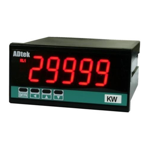
ADTEK MWH-10 User manual

MWH-10 Operating Manual 2017/10/17
1 / 39
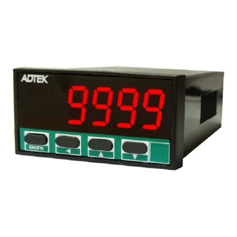
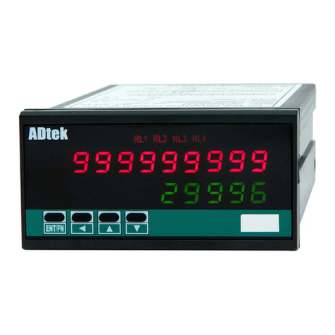
MWH-10 ACTIVE POWER & ENERGY METER
OPERATION MANUAL
■DESCRIPTIONS
MWH-10 Active power & Energy meter is destined with high accuracy measurement,
display, control and communication (Modbus RTU mode) with flexible functions and compact
size(96Wx48Hx120D). The main purpose is for power management of equipment, machinery
and consumption testing system.
At present, the electric cost in manufactory is higher and higher and the margin is slighter
and slighter. It’s more and more important that is to analyze and manage the electric cost. We
have designed the MWH-10 to supports the management of power consumption.
They have built in 2 External Control Inputs in standard, and 2 optional outputs in multi-cross
selection for 2 Relay, 1 Analogue, 1 Pulse and 1 RS485(Modbus RTU Mode) interface with
versatile functions such as remote I/O, alarm and communication. Please refer to the page
2/41~7/41 for detail description.
An innovation that has been designed in the meter. A timer has been built for accumulation
time setting of energy. When the time is over of setting, the energy will stop to accumulate; even
the load has been running. It’s very useful function for consumption testing of electric
appliances and equipments.
■FEATURES
●Measuring Active power & Energy / 1P2W, 1P3W, 3P3W, 3P4W Unbalanced
systems;
●Direct input 500V / 50A maximum with high accuracy current transformer.
●Dual display for 4 1/2 digits Active power/ 6 digits Batch energy & 10 digits
Energy and selectable engineer unit.
●2 relay can be programmed individual to correspond to Active power, Energy
or Batch energy with difference energize mode,
►Active Power: programmed Hi / Lo / Hi(Lo) Latch / Do with Start Delay /
Hysteresis / Energized & De-energized Delay functions, or to be a remote
control.
►Energy and Batch energy: programmed N/R/C mode with relay energized
period function.
●2 external control inputs can be programmed individual to correspond to
Active power, Energy/Batch energy or accumulation timer with difference
functions,
►Active Power(Watt): Relative PV (Tare) / PV Hold / Maxi. or Mini. Hold
►Energy/ Batch energy: Gate / Reset
►Other application: Start/Reset for accumulation Timer / DI (remote
monitoring) / Reset for Relay Energized Latch….
●Pulse output corresponds to energy and RS 485 communication port in option
■APPLICATIONS
Power consumption of Machinery management
Testing Instruments
Functions
●Safety & Protection Hi/Lo alarm and latch(hIhld / lOhld), Analogue output limited(aOlmt)
●Testing & Measuring Maximum/Minimum hold( maXh/ minIh), PV hold(pVhld), Relative
PV/Tare/∆PV(reLpv), Banks(bnK-_), accumulate energy timer(ttLtm)
●Remote Monitoring & Control RS485 communication port, Display function(rs485), ECI input
status( di), Relay energized( do)

MWH-10 Operating Manual 2017/10/17
2 / 39
RS 485 Modbus RTU Mode (up to 38400bps)
2 Relay Output:
Mode: Hi or Lo Energized / Energized Hold / DO
Functions:
Power: Start delay / Energized & De-energized delay / Hysteresis
Energy: N / R / C Mode
2 External Control Input:
Functions: Relative PV / PV Hold / Reset Max or Mini. Hold / DI /
Reset for Relay Energized Hold
Application: Thermal Switch / Circuit Breaker / Push Button /…
配電盤
MOTOR
Display: to show the value from
RS485 command of master
ENT/FN
▼
P L S
C O M
EC I 1
EC I 2
mwh
kwh
MK
kw
W
◄
WH
▲
■FUNCTION DEFINE
■Character Symbol
■Display Functions
A b C d E F G H i J K L M
a b c de f gh i j kl m
n o P q r S t U v W X y Z
no p qr s t u v w x y z
1 2 34 5 6 7 8 90 / .
1234567 8 90/.
There are dual display screen in MWH-10.
Please refer to the function description as below,
Display Screens
Up screen shows Energy.
Down screen can be programmed in Active power,
Batch energy or Timer(Option: accumulate energy
timer)
Display Functions in down screen
Programmable: pv / miNhd / maXhd /
batch / rs485
●pv(PV): Active power
●miNhd / maXhd: Minimum/Maximum Hold
When the [dsply]function in [input group]set
to be maXhd(Max. Hold) or miNhd(Mini. Hold), that
the meter will still display the values of PV in
maximum (or minimum) and the relative square
orange LED will be bright during power on, until
manual reset by front key in [user level],
Up/Down Key function has been done or ECI
terminal had been closed. The meter will update
immediately new maximum(minimum) values after
ECI is to be opened, or press Up/Down Key again.
The Reset functions will be described in ECI
functions.
Please paste the sticker
M.H
on the right side of
orange square LED to identify the status of display.
Max. ( Mini.) Hold & Reset
Reset the Max
(Mini) Hold by
ECI or F. Key
O
N
Level
Trigger
Maximum Hold
Present
Value
maXh
[dsply]
Mrst
[ecI_]
■Input Functions
Input Range Function
The meters had been set the input ranges and
calibration as per order code (ex. 0~5A or 0~1A)
in factory. The display of active power is
calculated by the input current, voltage and the
setting of PT and CT in [input group]. The
display of energy is accumulated by the display of
active power and timer in firmware. Please refer to
the description as below,
●Voltage input
The voltage input is 0 ~ 500Vℓℓ max. User can
connect directly to the meter if the measured
voltage is under 500Vℓℓ. In the case of PT installed,
user just set the primary and secondary voltage of
PT. The meter will calculate and display the active
power.
►The setting for voltage
Primary Voltage unit of PT: v(V) / kv(kV)
Primary Voltage of PT: 50.0V~999.99KV
Secondary Voltage of PT: 50.0~500.0V
●Current input
The current input is 0 ~ 1/ ~ 5/ ~ 50A. The input
range will be fixed in factory. If user specifies the
input for 50A input, please connect the meter with
the current transformer module (YMWH-CT10A)
that we offer with meter. Please find the modules
in box for 1P2W:1pc or 3P3W:2pcs or
3P4W:3pcs.
►The setting for current
Primary Current of CT: 1~9999.9A
Secondary Current of CT:1.000~9.999A
●Frequency: 50/60 Hz±3 Hz

MWH-10 Operating Manual 2017/10/17
3 / 39
●batch: Batch energy
This function is our innovation function.
User can use this function to measure and
analyze the electric consumption for each
production cycle in machinery, or the electric
consumption for each kind of product in a mass
production line.
For example,
A Reflow Machine for Product A and Product B
To set [dsply]to be batch(down screen shows
batch energy)
1.Engineer reset the energy and batch energy of
meter before producing the Product A, and then
go running.
After finished 500pcs of Product A
The energy shows 50.0kWh from 0.0
The Batch energy shows 50.0kWh from 0.0
2.The next order wants to produce Product B for
800pcs
Engineer reset the batch energy of meter before
producing the Product B, and then go running.
The energy shows 120.0kWh from 50.0
The Batch energy shows 70.0kWh from 0.0
According to the numbers of meter, engineer can
calculate the electric cost for each pc and model
as below,
the electric cost for Product A = 50.0kWh/500pcs
the electric cost for Product B = 70.0kWh/800pcs
It’s very easy to collect the data and report without
any extra cost, If the meter has built RS485 port
and I/O function.
●rs485(RS485 remote display)
When the [dsply]function set to be rs485, the
LED display no longer appear the input signal on
the meter then the down screen will show the data
from RS485 command. The data(number) will be
same as PV which it will compare with set-point,
analogue output and ECI functions so that is to
control analogue output, relay energized and so
on. At mean time, the energy will be accumulated
by the data in down screen.
Active power Max / Mini recording
In order to review & trace the drifting PV, the
meters will keep the values of maximum and
minimum in [ max]and [ min]of [user level]
during power on.
Active power (PV) Hold
When the [ ecI_](External Control input) set to be
pVhld(PV Hold) function in [eci group], that
display will be hold & kept, and the relative green
LED will be bright, when the ECI has been closed
or Up/Down Key function has been done, until it is
to be opened or press Up/Down Key again.
Please paste the sticker
PV.H
ECI
on the right side
of green square LED of ECI to identify the status of
display.
PV Hold & Reset
Present
Value
Reset Data
Hold by E.C.I.
or Front Key
O
N
Level
Trigger
ON
ON
PV Hold
pVhld
[ecI_]
Low Cut
Settable range from 0.00~100.00%.
The users can set a value here to cut the display
value to show "0".
●If the setting value is positive, it expressed the
PV will be 0 which it's within the range of
absolute value;
PV< l Setting value l, the display will be 0
EX: Low Cut is set for 0.50, if the display is from
-0.50~+0.50, that will be 0.
Low Cut set to be +0.50%
Low Cut is set for 0.50, if the PV is
from -0.50~+0.50, that display will be 0.
PV according
to input signal
Present
Value
Low cut
function
0.50%
-0.50%
)50
[lOcut]
Digital Fine Adjustment
Settable range from -19999~+29999 ;
Users can get "Fine Adjustment PV" by front key
on the meter for lower and/or higher points, and if
the user want to show the current input signals that
“Just Key-In” the value.
Especially, the [pVzro]&[pVspn]are not only in
zero & span of PV, but also any lower point for
[pVzro]& higher point for [pVspn]. The meter will
be linearization automotive for full scale.
The adjustment can be cleared in function
[ZSclr].
Default Input: [lOsc]: )00, [hIsc]: 19(99
Digital fine adjustment:
input 2.75V, [pVzro]set to be 8)00
input 9.00V, [pVspn]set to be 17)00
Display: Low point from 55.00 to 80.00
High point from 180.00 to 170.00
SCALE
INPUT
0V
10V
5V
2.75V
9.00V
19(99
[hIsc]
[lOsc]
)00
10)00
18)00
5%00
8)00
17)00
*Please make sure that the [pVzro]point must be
less than [pVspn]during the process of digital
fine adjustment. Generally, the internal should be

MWH-10 Operating Manual 2017/10/17
4 / 39
over 50% of input range. That may be made
bigger error in zero and span, if the interval is too
narrow.
Energy and Batch energy reset
There are 3 ways to reset the energy and batch
energy. In some case of application, it’s not allowed
to execute this function. Please contact with our
sales representative for the detail.
Timer for accumulation of energy(Optional
appendix code-SCT)
Settable range from 0.0(minutes)~
999(hours)59(minutes);
An innovation that has been designed in the
meter. A timer has been built for accumulation
time setting of energy. When the time is over of
setting, the energy will stop to accumulate; even
the load has been running. It’s very useful function
for consumption testing of electric appliances and
equipments.
Moving Average set to be 3
Sample 1
Sample 2
Sample 3
Sample 4
Sample 5
Sample 6
…….
In first 3 samples, Display Update Value
= (Sample 1 + Sample 2 + Sample 3)/3
Display Update Value
= (Sample 2 + Sample 3 + Sample 4)/3
Display Update Value
= (Sample 3 + Sample 4 + Sample 5)/3
Display Update Value
= (Sample 4 + Sample 5 + Sample 6)/3
Digital filter
Settable range from 0(None)/1~99 times.
The digital filter can reduce the influence of spark
noise caused by magnetic of coil.
If the values of samples are over digital filter
band(fix in firmware and about 5% of stable reading)
3 times (Digital Filter set to be 3) continuously, the
meter will admit the samples and update the new
reading. Otherwise, it will be as treat as a noise
and skip the samples.
Digital Filter set to be 3
Digital Filter Band
The values of samples are
two times only, so that the
reading will admit the
samples.
Digital Filter Function
The values of samples are
over the filter band and three
times, so that the reading will
accept the samples, and
update the reading.
Digital Filter Function
Present
Value
■Reading Stable Functions
Average Display update
Settable range: 1~99 times;
Jittery Display caused by the noise or unstable
signal. User can set number to average the
readings to get smoothly display.
Remark: The higher average setting will impact the
response time of Relay and Analogue
output slower.
The meter’s sampling is 15cycle/sec. If the
[ avg](Average) set to be 3, the meter will
express the sampling 3 readings and calculating
the average then update the display once. At
meantime, the display update will be 5 times/sec.
Average set to be 3
Sample 1
Sample 2
Sample 3
Sample 4
Sample 5
Sample 6
…….
Display Update Value =
(Sample 1 + Sample 2 + Sample 3)/3
Display Update Value =
(Sample 1 + Sample 2 + Sample 3)/3
Moving Average update
Settable range: 0(no function)/1~10 times;
Jittery Display caused by the reasons as like as
noise or unstable signal. User can set number to
average the readings, and get smoothly display.
Remark: The higher moving average setting
wouldn’t impact the response time of
Relay and Analogue output slower after
first 3 samples.
The meter’s sampling is 15cycle/sec. If the
[mVavg](Moving Average) set to be 3, in the
first cycle will be same as average function. In
following cycle, the function will get a new fourth
reading and throw away first reading to be newer
3reading, and calculating the average then update
display. At meantime, the display update will be 15
times/sec.

MWH-10 Operating Manual 2017/10/17
5 / 39
■Relay Functions
If the [ry_.md]has been set do, the relay will
be energized by RS485 command directly, and no
longer to compare with set-point.
Start delay band and Start delay time
The functions have been designed for,
1.To avoid alarm for the starting current of
inductive motor(6 times of rated current).
2.If the ry_.md relay energized mode has been set
to be lo(Lo) or lOhld(Lo & latch), the relay
will be energized, when the meter is power on
and no input due to the "0" display. User can set
a band and delay time to inhibit the energized of
relay.
Start band(Fig.2-)
Settable range from 0~9999 Counts
●Start delay time(Fig.2-)
Settable range from
0.0(second)~9(minutes)59.9(seconds);
Start Delay
Fig.2
Start Delay Time
Start Band
Hi Setting
Relay
Energized
ON
Inhibit
Inhibit
[ rYsb]
[ry_.sp]
[ rYsd]
Hysteresis(Fig.3-)
Settable range from 0~9999 Counts
The function is to avoid the relay on and off
frequently, when the display value is swing near by
the set point. The typical application is to control a
compressor. User can set a band to prevent the
relay on and off frequently
Relay energized delay(Fig.3-)
Settable range from
0.0(second)~9(minutes)59.9(seconds);
The function is to avoid the miss action caused by
noise. Sometime, the display value will swing
caused by spark of contactor. User can set a
period to delay the relay energized.
Relay de-energized delay(Fig.3-)
Settable range from
0.0(second)~9(minutes)59.9(seconds)
Energized / De-energized
Delay & Hysteresis
Fig.3
ON
Hysteresis
De-energized
delay time
Hi Setting
Relay
Energized
[ry_.sp]
[ry_.hy]
[ry_.rd]
[ry_.fd]
Energized delay time
MWH-10 offers two relay output with
Multi-Cross selection function. User can set the
relay functions to relative pv(Power), total
(Energy) or batch(Batch Energy). They can be
programmed individual with versatile control
functions. User programs easier in [relay
group]. Please refer to the detail description as
below,
To relative PV(Power)
Relay energized mode Hi / Lo / Hi.HLd / Lo.HLd /
DO
●Hi(Fig.1-): Relay will be energized when
PV > Set Point
●Lo(Fig.1-): Relay will be energized when
PV < Set Point
Hi / Lo Relay Energized
Fig.1
Hi Setting
Hi Relay Energized
ON
Lo Setting
Lo Relay Energized
ON
hi
lo
[ry_.sp]
[ry_.sp]
[ry_.md]
●Hi.HLd (Lo.HLd)
The relay energized and latched function is for
electrical safety and human protection.
For example, a current meter relay installed for
over current alarm of motor. Generally, over current
of motor caused by over load, mechanical dead
lock, aging of insulation and so on. In the case of
alarm of meter, if the user doesn't figure out the real
reason and re-start the motor. It may damage the
motor. The function is designed that must be
manual reset the alarm after checking out and
solving the issue. It's very important idea for
electrical safety and human protection.
If the PV Higher (or lower) than set-point, the relay
will be energized and latch until manual reset by
from key in [user level]or [ eci](ECI) input.
Hi(Lo) Energized Latch & Reset
Hi.HLd(High Hold)
Relay Energized
ON
ResettherelayHold
byECIorFront Key
ON
Level Trigger
Hi Setting
hIhld
[ry_.md]
rYrst
[ ecI_]
[ry_.sp]
●DO
The function has been designed that is not only a
meter but also an I/O interface. In the case of motor
control cabinet, it does normally can not get the
remote function. It's very easily to get the status of
switch and remote ON/OFF of the switch from CS2
series with RS485 function.

MWH-10 Operating Manual 2017/10/17
6 / 39
To relative Energy or Batch Energy
Relay energized mode N/R/C
For totalizer such as energy and batch energy, The
relay output is not only energizing with time but
also the reset of relay and totalizer.
●Relay output time(ry_.ot)
Settable range from
0.0(second)~9(minutes)59.9(seconds);
In the case of R and C mode set, the time is not
only control the relay energizing but also the reset
the totalizer(energy or batch energy). Please refer
to the description in following,
●N MODE
Energy/Batch energy & relay reset by manual
When the condition of Set Point is met:
1. The relay will be energized;
2. The totalizer will run as same as usual, until
manual reset by front key or by rear terminal, the
totalizer will be reset to “0” and the relay will be
de-energized.
Set
Point
Relay
Output
ON
Totalizer
Manual
Reset
●R MODE
Energy/Batch energy & relay reset by time
setting of relay output time(ry_.ot)
When the condition of Set Point is met:
1. The relay will be energized, until the time is over
Relay output time ry_.ot(Relay1(2) output
times).
2. The totalizer will run as same as usual; until the
time is over Relay output time ry_.ot(Relay1(2)
output time),The totalizer will be reset to “0”.
ON
Auto
Reset
Relay output Time
Totalizer
Set
Point
Relay
Output
●C MODE
Energy/Batch energy auto reset & relay reset
by time setting of relay output time(ry_.ot)
When the condition of Set Point is met:
1. The relay will be energized, until the time is over
Relay output time ry_.ot(Relay1(2) output
times).
2. The totalizer will be reset to “0”, then counts-up
from “0”.
ON
Relay
Output
Set
Point
Auto
Reset
Totalizer
Relay output Time
■External Control Inputs(ECI)
MWH-10 offers 2 point external control inputs
(ECI) with Multi-Cross selection function. User can
set the ECI functions to relative pv(Power),
total(Energy) or batch(Batch Energy). They
can be programmed individual with versatile
display and control functions. The front key
function can be set to execute ECI function. At
meantime, ECI terminals will be disabling. The
input from terminal has designed level trigger.
Please refer to description as below,
To relative PV(Power)
ECI Functions
Relative PV / PV Hold / Reset for Maximum or
Minimum Hold / DI(Digital Input) / Reset for Relay
Energized Latch
●Relative PV(Active power)
The [ ecI_]can be set to be reLpv(Relative PV)
function. When the ECI is closed, the reading will
show the differential value with PV(Active power).
●PV(Active power) Hold
The [ ecI_]can be set to be pVhld(PV Hold)
function. The display will be hold when the E.C.I. is
closed, until the ECI is to be open. Please refer to
the below figures.
PV Hold & Reset
Present
Value
Reset PV Hold
by E.C.I. or
Front Key
O
N
Level
Trigger
ON
ON
PV Hold
pVhld
[ecI_]
●Reset for Maximum or Minimum Hold
The [ ecI_] function can be set to be Mrst
function to reset the maximum and minimum value
by terminal of ECI.
Especially, the [dsply] function in [input group]
can be set to be to maXh or minIh to operate in
coordination with DO of PLC. It is easier to achieve
the maximum value testing in automation. Please
refer to the below figures.

MWH-10 Operating Manual 2017/10/17
7 / 39
Max. ( Mini.) Hold & Reset
Reset the Max
(Mini) Hold by
E.C.I. or F. Key
O
N
Level
Trigger
Maximum Hold
Present
Value
maXh
[dsply]
Mrst
[ecI_]
●DI(Digital Input)
The [ ecI_] can be set to be dI (Digital Input)
function, when the meter building in RS485 port.
The computer is easier to get a switch status
through the meter as like as DI of PLC.
●Reset for Relay Energized Latch
If the relay energized mode has been set to be
hIhld(Energized latch), and the [ ecI_]can be
set to be rYrst(Reset Relay function). When the
PV meets the condition of relay energizing, the
relay will be energized and latch until the ECI is to
be closed.
To relative Energy or Batch Energy
ECI Functions
Gate / Energy Gate / Batch energy Gate
Reset / Energy Reset / Batch energy Reset
Gate function
Gate for Energy / Batch Energy
Energy
/ Batch
Gate by ECI
or Front Key
O
N
Level Trigger
ON
ON
ON
●gate(Gate): Energy and Batch energy will be
stopped to count, when ECI is closed, until the
ECI open again.
●tLgte(Totalizer Gate): Energy will be stopped to
count, when ECI is closed, until the ECI open
again.
●bTgte(Batch Gate): Batch energy will be stopped
to count, when ECI is closed, until the ECI open
again.
Reset Functions
Reset for Energy / Batch Energy
Reset by ECI
or Front Key
O
N
Edge Trigger
ON
ON
Energy
/ Batch
●reset(Reset): Energy and Batch energy will be
reset to “0”, when ECI is closed, until the ECI
open again. The energy or batch energy will
accumulate from 0 after the ECI open.
●tLrst(Totalizer Reset) : Energy will be reset to
“0”, when ECI is closed, until the ECI open
again. The energy or batch energy will
accumulate from 0 after the ECI open.
●bTrst(Batch Reset) : Batch energy will be reset to
“0”, when ECI is closed, until the ECI open
again. The energy or batch energy will
accumulate from 0 after the ECI open.
Timer functions for accumulation of
energy(Option)
The ECI can be set to enable or reset the timer of
accumulation of Energy or Batch energy.
●tmRen(Timer enable) : Energy and Batch energy
will start to accumulate, when ECI is closed.
●tmRrs(Timer reset) : The timer of accumulation of
Energy and Batch energy will be reset, when
ECI is closed.
■Pulse Functions
The meter offers a pulse output to relative
energy or batch energy. It’s a popular application
to connection a DI of PLC to manage the power
consumption.
The pulse output is 1000Hz maximum, and
50% duty cycle(0.5msec. minimum).
Remark: The frequency of pulse will be changed
according to the consumption.
Pulse divider(plSdv)
Settable range from 1~9999.
►plSdv set to be 1: It will output 1 pulse,
when Energy(totalizer) increases “1Count”.
Ex: It will output 1 pulse, when energy from
12345.678 increase to 12345.679,
►plSdv set to be 1000: It will output 1 pulse,
when Energy(totalizer) increases “1000Count”.
Ex: It will output 1 pulse, when energy from
12345.678 increase to 12346.678.
●The maximum frequency of output is 1000Hz.
Please sets lower resolution of Energy(totalizer),
when the output over 1000Hz.
●plShi(Duty Cycle): User can set the period of
output high level from 0(Auto)~1/~5000x4ms
►Please specify Relay or Open Collect output in
order
■Analogue Output Functions
Please specify the output type either a 0~10V
or 4(0)~20mA in ordering. MWH-10 offers one
analogue output with Multi-Cross selection
function. User can program the output to relative
pv(Active Power), total (Energy) or
batch(Batch Energy), and also the output low and
high can be programmable which it's related to
various display values easier in [ao group].
Amend:2010/4/26: Add new function for plShi(Duty Cycle):

MWH-10 Operating Manual 2017/10/17
8 / 39
Reverse slope output is possible by reversing point
positions. Please refer to the detail description as
below,
The output range related to various display
values
Programmable range:
PV(Active power):0~99999
Totalizer(Energy):0000000000~9999999999
Totalizer(Batch energy): 000000~999999
●Analogue Output low related display
Low[aOls]
Setting the Display value Low to versus output
range Low(as like as 4mA in A4-20).
●Analogue Output high related display
high[aOhs]
Setting the Display value high to versus output
range high(as like as 20mA in A4-20).
Please refer to the figure as following,
SCALE
Default: [aOls]: 0.00, [aOhs]: 100.00
Change to [aOls]: 50.00, [aOhs]: 19(99
OUTPUT
)00
0.00%
100.00%
50.00%
10)00
5)00
19(99
[aOhs]
[aOls]
*The range between [aOhs]and [aOls]should
be over 20% of span minimum; otherwise, it will
reflect the less resolution of analogue output.
Fine Zero & Span Adjustment for Analog Output
Users can get Fine Adjustment of analogue output
by front key on the meter. Please connect standard
meter to the terminals of analogue output. To
press the front key(up or down key) of meter for
adjusting and checking the output.
●[aOzro]: Fine Zero Adjustment for Analog
Output; Settable range: -38011~27524;
●[aOspn]: Fine Span Adjustment for Analog
Output; Settable range: -38011~27524;
High Limited for Analog Output
Settable range: 0.00~110.00% of output High;
User can set the high limit of output to avoid
destroying the receiver or protection system.
Set Scaling: [lOsc]: )00, [hIsc]: 19(99;
Output: [aOls]: 5)00 (Display value Low),
[aOhs]: 15)00 (Display value High);
[aOlmt]: 8)00%( of Output Range)
0.00%
100.00%
50.00%
OUTPUT
Ao.LMt: 80.00%
80.00%
SCALE
19(99
[hIsc]
)00
[lOsc]
10)00
5)00
[aOls]
15)00
[aOhs]
[aOlmt]
■RS 485 Communication
MWH-10 supports Modbus RTU mode protocol
to be used as Remote Terminal Unit (RTU) for
monitoring and controlling in a SCADA (Supervisor
Control And Data Acquisition) system. The baud
rate can be up to 38400 bps. It's not only can be
read the measured value and DI (external control
inputs) status but also controls the relays output
(DO) by RS485 communication ports.
●Protocol: ModBus RTU Mode
●Baud Rate:
Programmable 1200/2400/4800/ 9600/ 19200/
38400
●Data Bits: 8 bits
●Stop Bits: Programmable 1 bit or 2 bits
●Parity: Programmable Even / Odd / None
●Divice Number: Settable 1~255
MWH-10 APPLICATION FOR RS485 WRINTING
RS 485 Modbus RTU Mode (up to 38400bps)
RS485 wiring 1.2KM maximum
Terminate Resistor:
ENT/FN
▼
PLS
CO M
EC I 1
EC I 2
mwh
kwh
MK
kw
W
◄
WH
▲
ENT/FN
▼
PLS
CO M
EC I 1
EC I 2
mwh
kwh
MK
kw
W
◄
WH
▲

MWH-10 Operating Manual 2017/10/17
9 / 39
■Bank Function(Suffix-3BK)
The function is for testing difference load with a same meter.
For example; a power consumption testing equipment; it has to measure multi-range with difference load. The meter
can be pre-set 4 groups parameters to show difference scales and relay energized with difference set-points. The
operator just selects the bank number (bank1) to meet the process (product A). To make easier operating and to
avoid making mistake in process operating.
4 banks pre-set for all relay functions are correspondence to 4 difference scaling, decimal point, above select by 3
External Control Inputs(E.C.I.) or front key.
Example: Current testing
Product A: Power consumption rated: 110Vx5Aac=550W; NG: over 550W
Product B: Power consumption rated: 220Vx20Aac=4400W(connection with CT); NG: over 4400W
Setting: BANK1: [Wdp]: )0 [pTpri]: 20)0 [pTsec]: 20)0[cTpri]: %0 [cTsec]: %000
[ry!md]: hi [ry!sp]: 55)0[ry!rd]: )0)5
BANK2: [Wdp]: 0[pTpri]: 50)0 [pTsec]: 50)0 [cTpri]: 2)0[cTsec]: %000
[ry!md]: hi [ry!sp]: 4400 [ry!rd]: )0!0
[ ecI1]: banK1 [ ecI2]: banK2; connect a selector (or DO of PLC) to ECI1 and ECI2 terminals
●The order want to produce Product A must switch selector to A(Label A on panel), and ECI.1 close that the square
green LED bright to express the meter will work as per bank1 set. When PV is over 550.0W that relay1 will be
energized.
●The second order want to produce Product B must selector to B(Label B on panel), and ECI.2 close that the square
green LED bright to express the meter will work as per bank2 set. When PV is over 4400W that relay1 will be
energized..
Only 1 Bank can be selected, if it is double selection. The priority is Bank1 > Bank2 > Bank3 in order,
■OEM function is wellcome

MWH-10 Operating Manual 2017/10/17
10 / 39
■ORDERING INFORMATION
ORDERING INFORMATION
MWH–10–
Connection
−
A Input
range
V Input
range
Input
Frequency
−
Optional
Output 1
Optional
Output 2
−
Aux.
Power
−
*Optional
Function
CODE
CONNECTION
CODE
INPUT RANGE
CODE
INPUT FREQ.
CODE
OUTPUT 1
CODE
OUTPUT 2
CODE
AUX. POWER
CODE
*OPTIONAL FUNC
12
1P2W Unbalanced
A1
0 ~ 1 A
5
50Hz ±3Hz
N
None
N
None
A
AC 115/230V
N
None
13
1P3W Unbalanced
A5
0 ~ 5 A
6
60Hz ±3Hz
PC
Pulse(O.C)
8
RS485
SCT
Accumulate Timer
33
3P3W Unbalanced
PR
Pulse(Relay)
R
Relay(2nd)
3BK
Bank function
34
3P4W Unbalanced
AF
0 ~ 50 A (with CT
module YMWH-CT10A)
I
4(0)~20 mA
V1
50 ~ 500V
V
0~10 V
ADH
AC85~264V /
DC100~300V
V2
220-110 V(1P3W)
R
Relay(1st)
ADL
DC20~56V
AO
VO
Specify (A & V i/p)
Can not support
any Relay output,
if pulse output is
specified.
OPTION 1
OPTION 4
OPTION
OPTION 2
Remark:The output functions can be specified
2 due to the limited terminals. Please
specified according to the list table of
output 1 and output 2.
OPTION 4
■INSTALLATION
Please check the specification, wire diagrams and functions on the lable of the meter before
installation.
■Dimensions & Panel Cut Out
■Installation
96.0
48.0
92.0+0.2
44.0+0.2
PANEL CUT-OUT
FRONT VIEW
Unit: mm
8.0
12.0
100.0
Dimensions: 96mm x 48mm x 120mm
Panel Cutout: 92mm x 44mm (advise)
1.0~8.0 mm
FIX HOLDER:
104 mm(L) / W M3
PANEL CUT-OUT:
92+0.2(W) x 44+0.2(H) mm
▼
PL
S
CO
M
EC
I1
EC
I2
m
wh
M
K
k
w
W
▲
W
H
▲
ENT/FN
■Wiring Diagram
Connector
Terminals A1~A16: 20A/600Vac,
M3.5, 12~22AWG;
Max torque: 13Kg-cm
Others:10A 300Vac, M2.6, 16~22AWG,
Max torque: 5Kg-cm
Please use cord end terminal.
7.0mm max
7.0mm max
2.0mm max
AUXILLARY POWER
Please check the voltage of power supplied
first, and then connect to the specified terminals.
Herein, recommended that power supplied to the
meter with protection by a fuse or circuit breaker.
Filter or Transformer
L
N
G
L
N
G
1AFuse
AC115/230V
AC85~264V
6
7
8
9
10

MWH-10 Operating Manual 2017/10/17
11 / 39
INPUT CONNECTION
Please casefully, PT can not be shorted and
CT can not be opened.
Optional : High precision CT module
(YMWH-CT10A 0.1class)
1P2W input connection
Connection with current transformer
L
N
SOURCE
11
12
13
14
15
16
Ak
LOAD
1
2
3
4
5
6
7
8
9
10
Al
External Control Input
ECI1
ECI2
COM
L
N
ADL: AC20~56V
DC20~56V
ADH: AC85~264V
DC100~300V
ADH
ADL
AC230V
AUX. POWER
AC115V
OUTPUT
TERMINALS
BLOCK
Connection with YMWH-CT10A
1P3W input connection
Connection with current transformer
N
L2
SOURCE
L1
11
12
13
14
15
16
L1k
P2
P1
Pn
LOAD
1
2
3
4
5
6
7
8
9
10
L1l
L2k
L2l
External Control
Input
ECI1
ECI2
COM
ADH
ADL
AC230V
AUX. POWER
AC115V
ADL: AC20~56V
DC20~56V
ADH: AC85~264V
DC100~300V
Connection with YMWH-CT10A
3P3W input connection
Connection with current transformer
B
C
SOURCE
A
11
12
13
14
15
16
Ak
Pc
Pa
Pb
LOAD
1
2
3
4
5
6
7
8
9
10
Al
Ck
Cl
External Control
Input
ECI1
ECI2
COM
ADH
ADL
AC230V
AUX. POWER
AC115V
ADL: AC20~56V
DC20~56V
ADH: AC85~264V
DC100~300V
Connection with YMWH-CT10A
3P4W input connection
Connection with current transformer
B
C
SOURCE
N
A
11
12
13
14
15
16
Ak
Pb
Pc
Pa
Pn
LOAD
1
2
3
4
5
6
7
8
9
10
Al
Bk
Bl
Ck
Cl
External Control
Input
ECI1
ECI2
COM
ADH
ADL
AC230V
AUX. POWER
AC115V
ADL: AC20~56V
DC20~56V
ADH: AC85~264V
DC100~300V

MWH-10 Operating Manual 2017/10/17
12 / 39
Connection with YMWH-CT10A
OUTPUT CONNECTION
Due to the terminals limited, the left two terminals
can be defined for relay, analogue or pulse output
and the right two terminals can be defined for relay
or RS485 port.
RS485 Communication Port
A
B
Max. Distance: 1200M
Terminate Resistor (at
latest unit):
120~300ohm/0.25W
(typical: 150ohm)
15
16
Pulse Output
Open Connect Output RelayContact Output
Max load
30V/60mA
(c)
(e)
15
16
15
16
Analogue Output
Specified in order for
0~10V or 4~20mA
15
16
2 Relay Output
Dual FORM-A,
1A/230Vac, 3A/115V
RL1
RL2
15
16
1 Relay output + RS485 Communication Port
RL1
15
16
A
B
1 Analogue output + RS485 Communication
Port
15
16
A
B
Amend:2010/4/26: Modify DC power supply (Code: ADL) range from DC20~90V to DC20~56V

MWH-10 Operating Manual 2017/10/17
13 / 39
■OPERATIONS
■Front Panel
ENT/FN
▼
P L S
CO M
EC I1
ECI 2
mwh
kwh
MK
kw
W
▲
WH
▲
Engineer Unit for
Active Energy
Engineer Unit for
Active Power
Down screen for 5 digts Active
Power / 6 digits Batch Energy / SCT
Up screen for
Active Energy
Pulse/RL output
Indication
Operation Key
Comm/RLstatus
Indication
ECI status
Indication
There are two display screens in MWH-10. The
decription as below,
Number screen
●Up screen:
: 0.28”(0.71cm) red
high-brightness LED for 10 digits Energy.
●Down screen:
0.28”(0.71cm) green
high-brightness LED for 5 digits Active power, 6
digits batch Energy or 999(H).59(M) Accumulation
timer.
I/O Status Indicators
●Relay Energized: 2 square red LEDs
RL1
display once Relay 1 has been energized;
RL2
display once Relay 2 has been energized;
●External Control Input: 2 square green LEDs
ECI1
display once ECI.1 has been closed(dry contact)
ECI2
display once ECI.2 has been closed(dry contact)
●RS485 Communication: 1 square orange LED
COM
will flash when the meter is receive or send
data, and
COM
flash quickly means the data
transient quicker.
●Max/Mini Hold indication:
99999. the decimal point on right displayed: To
display function which expressed it has been
selected in Maximum or Minimum Hold function.
●Pulse Output: 1 square orange LED
PLS
will flash when the pulse is output according to
the accumulateion of energy.
Engineer Unit
●Active Power: 3 square green LED for
W
/
KW
/
MW
programmable.
●Energy: 3 square red LED for
WH
/
/
programmable.
Stickers
Each meter with a sticker to describe what are the
functions and engineer label enclosure.
●Functions stickers
●Relay energized
H H
HH Energized
H i
Hi Energized
L o
Lo Energized
L L
LL Energized
D O
RS485 Energized
Hi. H
Hi Energized & Latch
Lo. H
Lo Energized & Latch
●ECI functions:
PV Hold
Tare
Digital Input
Maximum or Minimum Reset
Reset fo Relay Latch
●Engineer Label: over 80 types.
Operating Key: 4 keys for
Enter(Function) /
Shift(Escape) /
Up key /
Down key
Pass Code:
Settable range:0000~9999;
User must key-in the exactly pass cord for access
to [Programming Level]. Otherwise, the meter will
return to measuring page. If user forget the pass
code, please contact with your service window.
Function Lock: There are 4 levels programmable.
●none(None): no lock at all. User can access to all
level for checking and setting.
●user(User Level): User Level lock. User can
access to User Level for checking, but
can not setting.
●eng(Programming Level): Programming level lock.
User can access to programming level
for checking, but can not setting.
●all(ALL): All lock. User can access to all level for
checking but can not setting.
Front Key Function
●The
Key can be set to be the same function as
the setting of [ecI1](ECI).
Ex. The [ecI1]set to be pVhld and the function
[E1=up]set to be yes in [eci group]. When
user presses
Key, the PV will hold as like as
terminals of ECI1 close.
●The
Key can be set to be the same function as
the setting of [ecI2].
Ex. The [ecI2]set to be reL.pv and the function
[E2=dn]set to be yes in [eci group]. When
user presses
Key, the PV will show relative
value as like as terminals of ECI2 close.
If the front key function has been set, the
terminal input for ECI will be disabling.

MWH-10 Operating Manual 2017/10/17
14 / 39
■Error Masage
BEFORE POWER ON, PLEASE CHECK THE SPECIFICATION AND CONNECTION AGAIN.
SELF-DIAGNOSIS AND ERROR CODE:
DISPLAY
DESCRIPTION
REMARK
ovfl
Display is positive-overflow (Signal is over
display range)
(Please check the input signal)
-ovfl
Display is negative-overflow (Signal is under
display range)
(Please check the input signal)
ovfl
ADC is positive-overflow (Signal is higher than
input 120%)
(Please check the input signal)
-ovfl
ADC is negative-overflow (Signal is lower than
input -120%)
(Please check the input signal)
eep
fail
EEPROM occurs error
(Please send back to manufactory for
repaired)
aiCng
pv
Calibrating Input Signal do not process
(Please process Calibrating Input
Signal)
aic
fail
Calibrating Input Signal error
(Please check Calibrating Input Signal)
aoCng
pv
Calibrating Output Signal do not process
(Please process Calibrating Output
Signal)
aoc
fail
Calibrating Output Signal error
(Please check Calibrating Output Signal)
■Operating Key:
*Please access to the Engineer Level to check and set the parameters when users start to run the meter
Operating Key: 4 keys for
Enter(Function) /
Shift(Escape) /
Up key /
Down key
The meter has desgined operation similar as PC's
and
Enter
. In any page, press
key means
"enter" or "confirm setting", and press
key means "escape(
Esc
)" or "shift".
In Engineer Level, the screen will return to Measuring Page after do not press any key over 2 minutes, or
press
for 1 second.
Function Index
Setting Status
(=
)
Enter/Fun key
(1) In any page, press
to access
the level or function index
(2) From the function index to
access setting status
(3) Setting Confirmed, save to EEProm and go to next
function index
(=
)
Shift key
(1) In measuring page, press
for 1 second to access user
level.
(2) In function index, press
for 1
second to go back upper level.
(3) In function group index, press
for 1 second to go back
measuring page
(4) In seting status, press
to Shift the setting
position.
(5) In seting status, press
for 1 second to abort
setting and go back this function index.
(=
)
Up key
(1) In function index, press
to
go back to previous function
index
(2) In setting status for function, press
to select
function
(3) During number Setting, press
can roll the digit
up
(=
)
Down key
(1) In Function Index Page, press
will go to the next Function
Index Page.
(2) In setting status for function, press
to select
function
(3) During number Setting, press
can roll the digit
down.

MWH-10 Operating Manual 2017/10/17
15 / 39
■Operating Steps
User Level
INDEX
STEPS
FUNCTION DESCRIPTION
PARAMETERS & SETTING
SET
POWER
ON
Please check the specification and
wiring diagrams firstly.
******
******
Self-diagnosis (LED All bright)
**********
Energy
******
Batch Energy
0
mwh!0
Model
mwh!0: Activepower/Energy
0
ver@0
Firmware version
0
3p3w
System connection
999999
29999
Measuring Page
(10 digits Energy + 5 digits Active power or
10 digits Energy + 6 digits Batch energy)
Press
for 1 second to access [User
Level]
0−0−1
29999
pv
This page will show out, when
[dsply](step A-12) function has not set
to be pv .
pv(Pv): Present Value;
Press
for 1 second return
to Measuring Page
0−0−2
999999
batch
This page will show out, when
[dsply](step A-12) function has not set
to be batch .
batch(batch): Batch energy
0−1
10000
ry!sp
10000
20000
This page will show out, when Relay
function has specified in order
ry!sp(rY1.SP):Relay 1 Set-point
◘Please confirm the energized mode of
relay 1 before setting.
Settable range:
Active power: 0~99999
Energy: 0~9999999999
Batch energy: 0~999999
Shift
Up
Down
Enter
0−2
10000
ry@sp
10000
20000
This page will show out, when Relay
function has specified in order
ry@sp(rY2.SP):Relay 2 Set-point
◘Please confirm the energized mode of
relay 1 before setting.
Settable range:
Active power: 0~99999
Energy: 0~9999999999
Batch energy: 0~999999
Shift
Up
Down
Enter
Next Page

MWH-10 Operating Manual 2017/10/17
16 / 39
0−3
no
rYrst
no
yes
rYrst(rY.rSt): Reset for energized
latch of Relay;
If the [ry_.md](step B-3/-7) set to be
hIhld or lOhld, and the present
value(PV) reach to the condition of relay
energising, the relay will be energized
and latching.
At mean time, user can reset the relay
latching in here.
Be careful, the relay has been energizing
and latching, if the PV still reach to the
condition of relay energized, enven user
had set here to reset the relay latching.
Programmable: yes / no
yes(Yes): reset the relay
latching.
no(No): abort to reset the
relay latching.
&
Selection
Enter
0−4
0
min
min(Min): the Minimum value of PV
saving;
The meter will save the minimum of PV
during power on, until reset in [ Mrst]
(step 0-6) or power off. It will save newest
minimum PV after reset.
Review only
0−5
29999
max
max(Max): the Maximum value of PV
saving;
The meter will save the maximum of PV
during power on, until reset in [ Mrst]
(step 0-6) or power off. It will save newest
maximum PV after reset.
Review only
0−6
no
Mrst
no
yes
Mrst(M.rSt): reset the saved value of
Maximum & Minimum;
The values of maximum and minimum
can be reset in here. It will save newest
maximum and minimum after reset.
Programmable: yes / no
yes(Yes): to reset the saved
value of maximum and
minimum.
no(No): abort to reset the
saved values of maximum
and minimum.
&
Selection
Enter
0−7
ver!0
mwH10
Model & Version of the meters
mwH10(MWH-10):Active power & Energy
ver!0(Ver 1.0): Firmware version
Review only
It will be announced in our
website www.adtek.com.tw,
when it had been versions
updated.
0−8
)0)00
ttLtm
Option(Appendix code-SCT)
ttLtm(Accumulation timer): Timer for
accumulateion of Energy or Batch
energy
Settable range:
0:00~999(H):59(M)
Shift
Up
Down
Enter
0−9
bnk-0
bank
Option(Appendix Code-3BK)
bank: Bank selection
Programmable:
bnk-0 / bnk-1 / bnk-2 /
bnk-3
&
Selection
Enter
0−0−1
29999
pv
Return to the first page
Press
for 1 second to back to
Measuring Page in any page.

MWH-10 Operating Manual 2017/10/17
17 / 39
Programming Level
INDEX
STEPS
FUNCTION DESCRIPTION
PARAMETERS & SETTING
SET
999999
29999
MEASURING PAGE
0000
Pcode
Default:1000
0000
1000
Enter the pass code to access
Programming Level
If user wants to change the
pass code, please go to step
A-19 to set. Please remind the
new pass code.
Pass Code
INPUT
GROUP
RELAY
GROUP
EXTERNAL
CONTROL
INPUT GROUP
ANALOGUE
OUTPUT
GROUP
RS485
GROUP
PRESS
TO ACCESS
PRESS
TO ACCESS
PRESS
TO ACCESS
PRESS
TO ACCESS
PRESS
TO ACCESS
Input Group
INDEX
STEPS
FUNCTION DESCRIPTION
PARAMETERS & SETTING
SET
group
input
INPUT GROUP INDEX PAGE
In following pages, press
for 1 second to back INPUT
GROUP INDEX PAGE
[input group].
A−1
v
Vunit
v
kv
Vunit: Unit for voltage of PT's primary
Programmable:
v(V) / kv(kV)
&
Selection
Enter
A−2
50)0
pTpri
50)0
50)0
pTpri: Primary voltage of PT
To figure out the primary volatge of PT,
and to set the value in here directly.
Please don't change the default setting
(500.0), if the system dosen't install PT.
Remark:
Please pay attention to the setting of unit
of volatge on last page. the meter will
combine the setting of unit(Vunit) and
value(pTpri) to caculate the display.
For example,
Once the Vunit set to be kv,and
the pTpri set to be 45)0, It means the
setting of Pt's primary is 450.0KV。
Settable range:
50.0V~999.99KV
Shift
Up
Down
Enter
Next Page
YES
Press
for 1 second to back Measuring Page
NO

MWH-10 Operating Manual 2017/10/17
18 / 39
A−3
50)0
pTsec
50)0
50)0
pTsec: Secondary voltage of PT
To figure out the secondary volatge of PT,
and to set the value in here directly.
Please don't change the default setting
(500.0), if the system dosen't install PT.
Settable range: 50.0V~500.0V
Shift
Up
Down
Enter
A−4
5)0
cTpri
5)0
10)0
cTpri: Primary current of CT
To figure out the primary current of CT,
and to set the value in here directly.
Settable range: 1~9999.9A
Shift
Up
Down
Enter
A−5
%000
cTsec
%000
%000
cTsec: Secondary current of CT
To figure out the secondary current of CT,
and to set the value in here directly.
Settable range: 1.000~9.999A
Shift
Up
Down
Enter
A−6
1k
Wunt
1k
)01m
Wunt: Unit of Active power(Watt)
Programmable:
1(W) / )01k(W) /
)1k(W) / 1k(W) /
)01m(W) / )1m(W) /
1m(W)
&
Selection
Enter
A−7
0
pVzro
0
10
pVzro: Fine low point Adjustment for
Active power(PV) display;
For Zero & Span of PV, users can get the
"Fine Adjustment" by front key. It's a easy
way to “Just Key-In” the value that the
user want to show in the current input
signal.
Especially, the [pVzro]&[pVspn]are
not only in zero & span of PV, but also
any lower point for [pVzro]& higher point
for [pVspn]. The meter will linearizate for
full scale.
Settable range: 0~99999
Shift
Up
Down
Enter
Default Input: [lOsc]: )00, [hIsc]: 19(99
Digital fine adjut.: input 2.75V, [pVzro]set to be 8)00
input 9.00V, [pVspn]set to be 17)00
Display: Low point from 55.00 to 80.00
High point from 180.00 tp 170.00
SCALE
INPUT
0V
10V
5V
2.75V
9.00V
19(99
[hIsc]
[lOsc]
)00
10)00
18)00
5%00
8)00
17)00
A−8
0
pVspn
0
16800
pVspn: Fine high point Adjustment for
Active power(PV) display;
It's same function as like as [pVzro].
Settable range: 0~99999
Shift
Up
Down
Enter
A−9
none
ZSclr
none
both
ZSclr: Clear Fine Low / High points
Adjustment for Active power(PV)
display;
Programmable:
none(None): Do not clear the
fine Low / High adjustment.
pV.zro(PV.Zro): To clear the
fine Low adjustment.
pV.spn (PV.SPn): To clear the
fine High adjustment.
both(Both): To clear the fine
Low and High adjustment.
&
Selection
Enter
Next Page

MWH-10 Operating Manual 2017/10/17
19 / 39
A−10
1k
wHunt
1k
)01m
wHunt: Unit of Energy(Watt-hour)
Generally, the unit and resolution of
energy is same setting as active power.
MWH-10 can be set difference unit &
resolution in Active power and Energy so
that use in verious purpose. However,
please pay attention, difference unit &
resolution will make accumulation speed
of energy difference.
Programmable:
1(Wh) / )01k(Wh) /
)1k(Wh) / 1k(Wh) /
)01m(Wh) / )1m(Wh) /
1m(Wh)
&
Selection
Enter
A−11
rcycl
ofLmd
rcycl
ovfl
ofLmd: Running mode after overflow
for Energy
Programmable:
ovfl(Over-Flow):The up
screen will shows ovfl
and stop to accumulate, once
the energy is overflow.
rcycl(Recycle): The up screen
will re-start to accumulate the
energy from 0, once the
energy is overflow.
&
Selection
Enter
A−12
pv
dsply
pv
ovfl
dsply: Display Function for down
screen
When the [dsply]function set to be
rs485, At meantime, the display is no
longer express the input signal. The PV
screen will show the number from RS485
command & data. The data(number) will
be same as PV that it will compare with
set-point, analogue output and ECI
functions so that is to control analogue
output, relay energized and so on.
Programmable:
pv(PV):shows Active
power(PV)
miNhd(Min.Hd):Minimum Hold
of Active power
maXhd(MAX.Hd):Maximum Hold
of Active power
batch(Batch):shows batch
energy
rs485(RS485):Remote
displayed from RS485
command of master.
Option function
ttLtm:Timer for accumulation of
energy
&
Selection
Enter
A−13
)00
lOcut
000)0
010)0
lOcut: Low Cut for the Active power
If the setting value is positive, it means
the PV is in the range of absolute value
will be 0;
PV≤ I Setting value I, the display will be 0.
If the setting value is negative, it
expressed the PV will be X which it's
under the setting value;
PV< Setting value, the display will be
X(Setting value).
Settable range: 0.00~100.00%
Shift
Up
Down
Enter
Low Cut set to be +0.50
Low Cut is set for 0.50, if the PV is
from -0.50~+0.50, that display will be 0.
PV according
to input signal
Present
Value
Low cut
function
0.50
-0.50
)50
[lOcut]
Next Page

MWH-10 Operating Manual 2017/10/17
20 / 39
A−14
5
avg
05
99
avg: Average update for the Active
power
Jittery Display caused by the noise or
unstable signal. User can set number to
average the readings to get smoothly
display.
The meter’s sampling is 15 cycles/sec. If
the [avg](Average) set to be the 3,
which means the meter is sampling 3
readings, and calculating the average to
update display once. At meantime, the
display update will be 5 times/sec.
Settable range:
1(no function)~99 times
Shift
Up
Down
Enter
A−15
1
Mavg
01
10
Mavg: Moving Average update for the
Active power
Jittery Display caused by the reasons as
like as noise or unstable signal. User can
set number to average the readings, and
get smoothly display.
The meter’s sampling is 15 cycles/sec. If
the [mVavg](Moving Average) set to be the
3, which the first cycle will be same as
average function. In following cycles, the
function will get a new fourth reading and
throw away first reading which the purpose
of keeping the newest 3 reading, and
calculating the average then update
display. At meantime, the display updated
will be 15 times/sec.
Settable range:
0(no function)/1~10 times;
Shift
Up
Down
Enter
A−16
0
Dfilt
00
99
Dfilt(d.FiLt): Digital filter for the
Active power
The digital filter can reduce the magnetic
noise or EMI in the field.
If the values of samples are over digital
filter band(fix in firmware and about 5% of
stable reading) 3 times (Digital Filter set to
be 3) continuously, the meter will admit the
samples and update the new reading.
Otherwise, it will be as treat as a noise
and skip the samples.
Settable range:
0(no function)/1~99 times.
Shift
Up
Down
Enter
A−17
1
plSdv
1
9999
Option: The function will be shown, if
pulse output has specified in ordering
plSdv: Pulse divider
►plSdv set to be 1: It will output 1
pulse, when Energy(totalizer) increases
“1Count”.
Ex: It will output 1 pulse, when energy
from 12345.678 increse to 12345.679,
►plSdv set to be 1000: It will output 1
pulse, when Energy(totalizer) increases
“1000Count”.
Ex: It will output 1 pulse, when energy
from 12345.678 increase to 12346.678.
Settable range: 1~9999
Remark:
The maximum frequency of
output is 1000Hz.
Shift
Up
Down
Enter
Next Page
This manual suits for next models
1
Table of contents
Other ADTEK Measuring Instrument manuals
Popular Measuring Instrument manuals by other brands

Mitutoyo
Mitutoyo QM-Height Series user manual
Union
Union INCA3051 Translation of the original operating instructions
Emerson
Emerson Fisher 4320 instruction manual
Trotec
Trotec BF06 operating manual
Bender
Bender grass valley KMX-4911 quick start guide
Keysight Technologies
Keysight Technologies UXA N9040B Installation note
