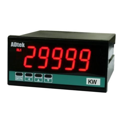
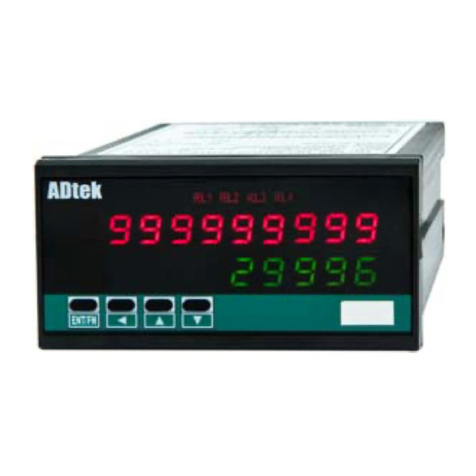
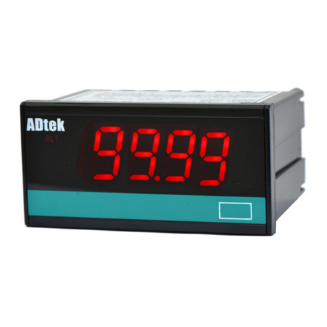
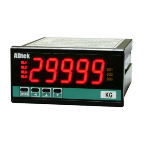
manuals.online logo
Brands
  1. Home
  2. •
  3. Brands
  4. •
  5. ADTEK
  6. •
  7. Measuring Instrument
  8. •
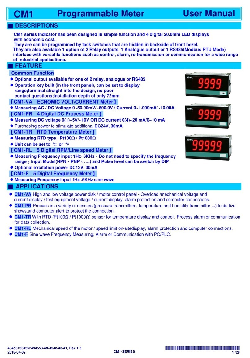
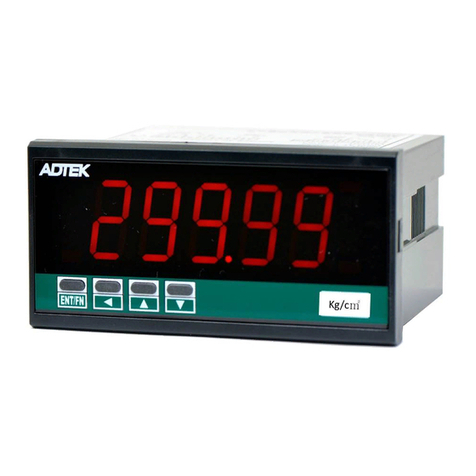
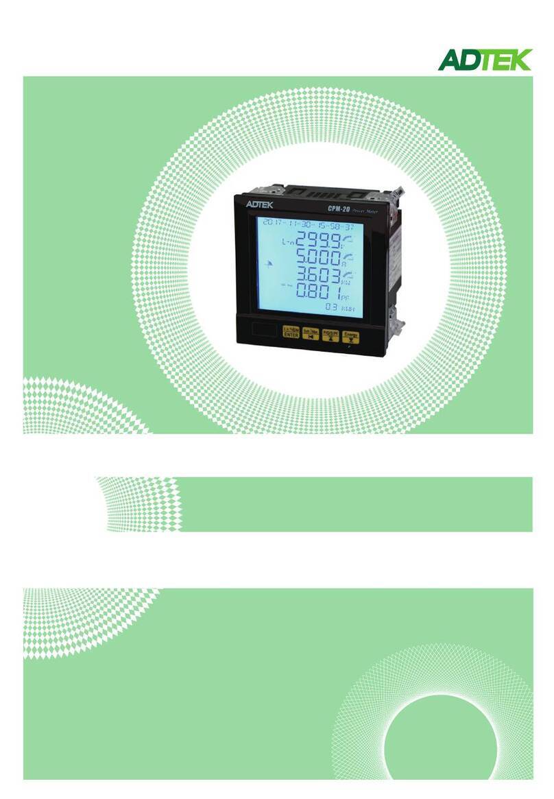
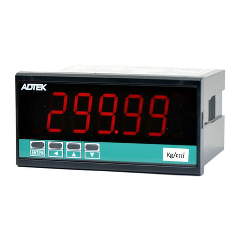
  9. ADTEK NED User manual

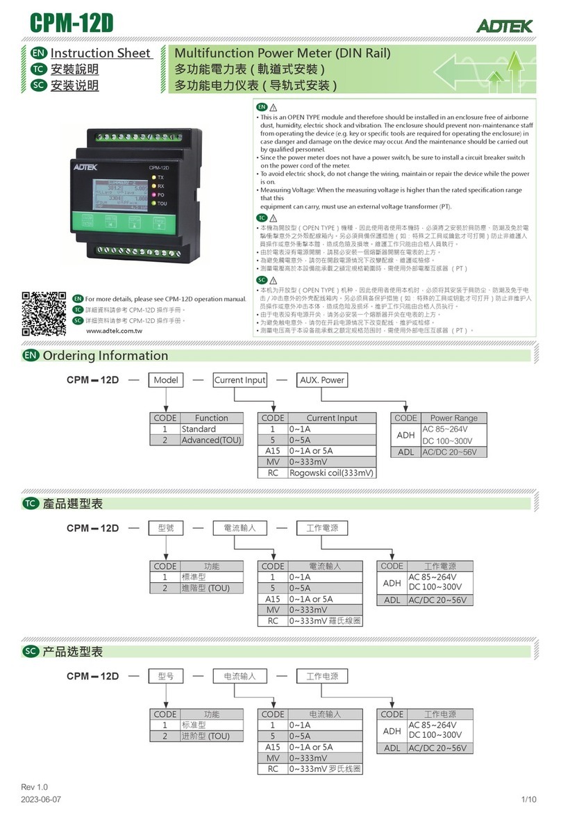
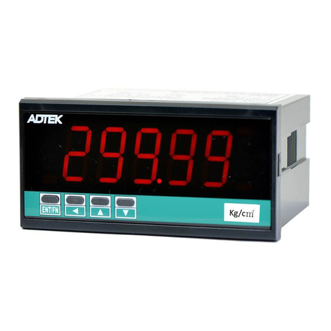
ADTEK NED User manual

Multifunction Indicator
NED
Rev 1.0
2021-05
Operation Manual
NED
AL1-the 1st alarm output
AL2-the 2nd alarm output
1.Please do not change the parameter setting that have been set by
the supplier, but contact them for any additional inquires.
2.Please check if the specification of the sensor( voltage, input
signal, and output device) is consistent with the indicator before
installation.
3.Please refer to the wiring diagram before proceeding, and check
the positive and negative charges while using thermocouple or
analogue input. For thermocouple, please use correct compensating
cable to avoid temperature difference.
4.Please build isolation between the power line and signal input line
to avoid Electromagnetic Interference(EMI).
Multi Functional IndicatorNED
Indicator light
■
803
℃
Size chart
■Button
■
S
Press to enter the 1st-order parameter
S
+ Press to enter the 2nd-order parameter
Press to increase the number of parameter
Press to decrease the number of parameter
SSS
Attention: parameter setting& wiring
■
Wiring diagram:
■
123 4
AL1
NC
5
NCNO NOCOM COM
90~264VAC
24VDC AB B
DC0-10V
DC2-10V
DC4-20mA
DC24 DC24
789 10 11 12 13 14 15
aux power
Power
T/C
RS485
0-10V
INPUT
4-20mA
PT100
6
AL2 RS485
T/C
1 2 3 4 5 6 7 8 9 10 11 12 13 14 15
Voltage
90~264VAC
AL1 AL2
NC NO
COM
NC NO
COM T/C
A B B
-
+
-
+
℃DC
24V
-
+
Temperature
sensor
<example 1> wiring diagram for single layer
-
+
1 2 3 4 6 7 85 9 11
10 12 13 14 15
Voltage
90~264VAC
AL1 AL2
AL1 AL2
9 11
10 12 13 14 15
-
+
-
+
-
+
-
+
T/C
T/C
A B B
A B B
NC NO
COM
NC NO
COM
NC NO
COM
NC NO
COM
Humidity sensor
℃
GND
㆒ v+
+
%
1234
<example 2> wiring diagram for double layers
-
+
-
+
DC24V
wiring diagram stickers & common specification
1 2 3 4 6 7 85
1
800
℃
807
溫度
℃
8007
Co2
ppm
800009
LUX
8007
Co2
ppm
化碳
二氧
15
15 15
15
15
37
45 45
65
65
7
7
7
7
7
Unit:cm
transmit
transmit
aux power
Press to return to the main menu
NED
The 1st set of alarm setting( additional purchase)
PV-temperature adjustment : controlled by PV+PVOF that can replace present
display value, and correct the temperature difference
Description setting range default value
1st-order parameter( press to proceed)
■
S
A1SP
A1HY
A2SP
A2HY
PVOF
a1sp
a1hy
a2sp
a2hy
pvof
The 1st set of selected temperature range with alarm turning off. Please note that
it needs to proceed with A1FU and A1SP( additional purchase)
The 2nd set of alarm setting( additional purchase)
The 2nd set of selected temperature range with alarm turning off. Please note that
it needs to proceed with A2FU and A2SP( additional purchase)
-1999~9999
-1999~9999
-1999~9999
-1999~9999
-1000~2000
(-100.0~200.0)
10.00
000.0
10.00
000.0
000.0
2nd-order parameter( press + to proceed)
■
S
type
TYPE
Input type: thermocouple, platinum resistance, and analogue input:
The input setting range is as below
Please refer to
the chart
(on the left side)
The factory
will set the
value
according to
the
requirement
Decimal Place
Setting for thermocouple/platinum resistance: 0000/000.0
Setting for analogue input: 0000/000.0/00.00/0.000
Please check all parameter setting once the setting of decimal place is done
Description
setting range
default value
UNIT
DP
unit
dp
Please do not change the factory setting
TYPE RANGE( )℃ RANGE(℉)
RSP
MA
V
MV
D-PT
C
N
S
R
B
E
T
K
J
RSP
MA
V
MV
D-PT
C
N
S
R
B
E
T
K
J
input signal of PLC/DDC/PC
-1999~9999
-1999~9999
-1999~9999
-200~850
-50~1800
-50~1300
0~1750
0~1750
0~1800
-50~750
-270~400
-50~1370
-50~1000
-328~1652
-58~3272
-58~3272
32~3182
32~3182
32~3272
-58~1382
-454~752
-58~1832
-58~2498
factory setting eng
0000
000.0
00.00
0.000
0000
LOLTlolt temperature reaches low set point
temperature reaches high set point
HILT
hilt
aifu A1FU
The 1st set of alarm
(1)off: turn off the alarm
(2)hi: alarm goes off when the temperature exceeds high alarm set point
(3)lo: alarm goes off when the temperature exceeds low alarm set point
aimd A1MD Please do not change the factory setting
a2fu A2FU
The 2nd set of alarm
(1)off: turn off the alarm
(2)hi: alarm goes off when the temperature exceeds high alarm set point
(3)lo: alarm goes off when the temperature exceeds low alarm set point
a2md A2MD Please do not change the factory setting
dir Transmission parameter: 4.20 means positive; 20.4 means reverse( additional purchase)
DIR
mal Please do not change the factory setting
MAL
mah Please do not change the factory setting
MAH
user-defined
user-defined
0000
9999
Please refer to
the column
( on the left)
factory setting
factory setting
factory setting
factory setting
scal
scah
SCAL
SCAH
Analogue input voltage/current at a low set point
Analogue input voltage/current at a high set point
factory setting
9999~-1999
9999~-1999
hi
none
lo
none
4.20
04.00
20.00
user-defined
user-defined
2
Please refer to
the column on
the left
Parameter table
Parameter table
NED
CUT
Analogue voltage/ current
none: no default value
lo: It shows 4mA when an input value reaches 4mA or goes under low limit set value
hi: It shows 20mA when an input signal reaches 20mA or goes above high limit set value
hilo: Have two modes set at the same time
FILT
Digital filter: average value of temperature
Larger sample sizes set by the filter will show a stable present value(PV) that runs slowly;
while smaller sample sizes set by the filter will show unstable present value(PV) that runs
quickly.
BAUD
Please select the required baud rates( Bit/Sec) while proceeding RS485 serial
communication. The parameter is invalid without setting.
ADDR
Can be defined as the address of the remote when RS485 serial communication is
working. Please note that each device only has single salve address( 1 byte). The
parameter is invalid without setting.
RTU
Remote terminal unit
LOCK
Please do not change the factory setting
Description
Parameter table setting range default value
filt
baud
addr
rtu
lock
factory setting
2.4k,4.8k
9.6k,192k
1~255
factory setting
n81,n82
e81,o81
cut factory setting none
0
9.6k
1
n82
100
RS485 communication
■
Communications Protocol: ModbusRTU
Baud rates: 9600, 19200 bps
Address: 1~255
Parity: N81,N82,O81,E81
Example
■
1. Reading present value(PV)
Send command:(16 bit)
Address Command positional parameters Read length CRC
01 04 10 02 00 01 94 CA
Address Command Temperature value( returned)

Length( returned) CRC
01 04 02 01 09
Return command:(16 bit)
The returned value below are the 1st set of temperature value
01 09 It will be 26.5C as a demical
2. Input TYPE
Send command:(16 bit): Set TYPE as DPT
Address Command Positional parameters Input value CRC
01 06 00 00 00 09 49 CC
Debug
■
1. Check the setting of USB/RS 232 port on PC
2. Check the setting of address, baud rate, and parity(N81, N82, O81, E81)
3. Check the positive/negative connection of RS485 port
3
NED
4
5
NED

Other ADTEK Measuring Instrument manuals

ADTEK MWH-10 User manual

ADTEK

ADTEK MWH-10 User manual

ADTEK CS2-SG User manual

ADTEK

ADTEK CS2-SG User manual

ADTEK CS1-SG User manual

ADTEK

ADTEK CS1-SG User manual

ADTEK CM1-TC User manual

ADTEK

ADTEK CM1-TC User manual

ADTEK CPM-10 User manual

ADTEK

ADTEK CPM-10 User manual

ADTEK CS2-PR User manual

ADTEK

ADTEK CS2-PR User manual

ADTEK AFM-8A User manual

ADTEK

ADTEK AFM-8A User manual

ADTEK CPM-20 Series User manual

ADTEK

ADTEK CPM-20 Series User manual

ADTEK CPM-21 User manual

ADTEK

ADTEK CPM-21 User manual

ADTEK CPM-12A User manual

ADTEK

ADTEK CPM-12A User manual

ADTEK CS2-T User manual

ADTEK

ADTEK CS2-T User manual

ADTEK CPM-12D User manual

ADTEK

ADTEK CPM-12D User manual

ADTEK CS2-MC User manual

ADTEK

ADTEK CS2-MC User manual

ADTEK CPM-12B User manual

ADTEK

ADTEK CPM-12B User manual

ADTEK CS1 Series User manual

ADTEK

ADTEK CS1 Series User manual

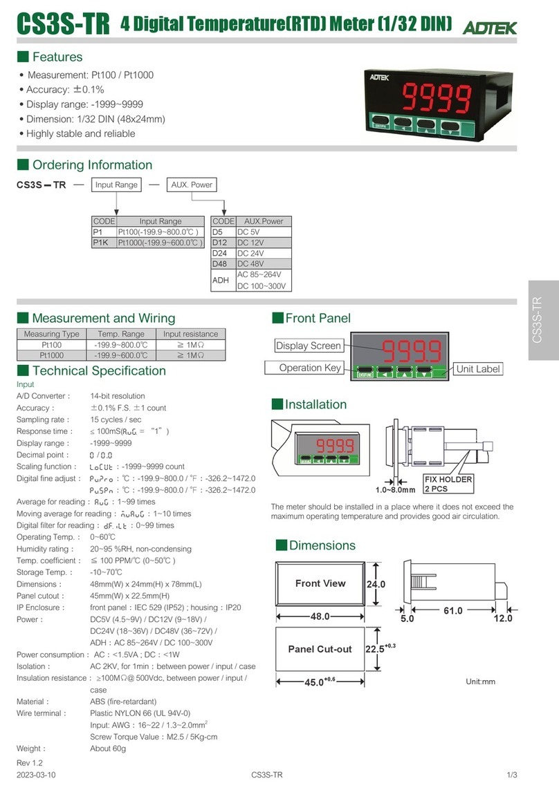
ADTEK CS3S-TR User manual

ADTEK

ADTEK CS3S-TR User manual

ADTEK CS2-SG User manual

ADTEK

ADTEK CS2-SG User manual

ADTEK MW-5 User manual

ADTEK

ADTEK MW-5 User manual

ADTEK AEM-DRK User manual

ADTEK

ADTEK AEM-DRK User manual

ADTEK CS2-VA User manual

ADTEK

ADTEK CS2-VA User manual

ADTEK MWH-8W User manual

ADTEK

ADTEK MWH-8W User manual

ADTEK CPM-12D User manual

ADTEK

ADTEK CPM-12D User manual

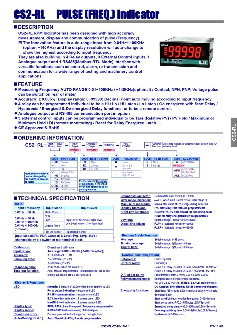
ADTEK CS2-RL User manual

ADTEK

ADTEK CS2-RL User manual

ADTEK AEM-DRB User manual

ADTEK

ADTEK AEM-DRB User manual

Popular Measuring Instrument manuals by other brands

Azbil MagneW FLEX+ user manual

Azbil

Azbil MagneW FLEX+ user manual

TPI 709R instruction manual

TPI

TPI 709R instruction manual

yellow jacket eVac Pro Operation and maintenance manual

yellow jacket

yellow jacket eVac Pro Operation and maintenance manual

MCR Technologies Weigh Shark manual

MCR Technologies

MCR Technologies Weigh Shark manual

AvMap EngiBOX User and installation manual

AvMap

AvMap EngiBOX User and installation manual

Badger Meter ModMAG M1000 Installation and operation manual

Badger Meter

Badger Meter ModMAG M1000 Installation and operation manual

REED R5060 instruction manual

REED

REED R5060 instruction manual

TOOLCRAFT 2182452 operating instructions

TOOLCRAFT

TOOLCRAFT 2182452 operating instructions

Digifly VL 100 RACER manual

Digifly

Digifly VL 100 RACER manual

WILGER EFMS Installation and operation manual

WILGER

WILGER EFMS Installation and operation manual

Mirion Technologies RDS-32 quick guide

Mirion Technologies

Mirion Technologies RDS-32 quick guide

Mitutoyo SJ-210 user manual

Mitutoyo

Mitutoyo SJ-210 user manual

Hach sensION+ EC71 manual

Hach

Hach sensION+ EC71 manual

TQC Sheen PowderTAG operating instructions

TQC Sheen

TQC Sheen PowderTAG operating instructions

AEMC JM810A user manual

AEMC

AEMC JM810A user manual

FMT Swiss AG Digital In-Line Meter operating instructions

FMT Swiss AG

FMT Swiss AG Digital In-Line Meter operating instructions

Major tech MT920 instruction manual

Major tech

Major tech MT920 instruction manual

Dytran 3085C operating guide

Dytran

Dytran 3085C operating guide

manuals.online logo
manuals.online logoBrands
  • About & Mission
  • Contact us
  • Privacy Policy
  • Terms and Conditions

Copyright 2025 Manuals.Online. All Rights Reserved.