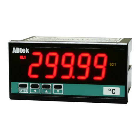
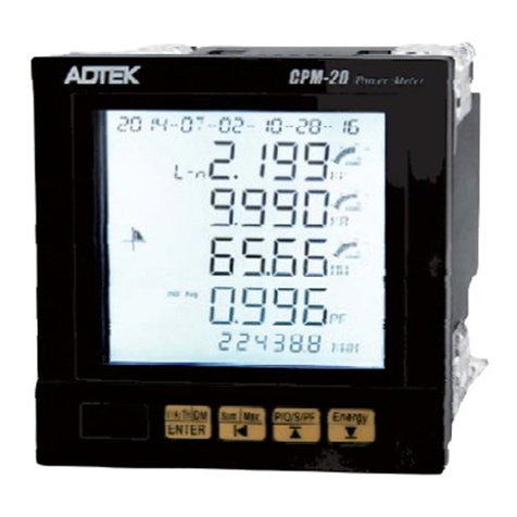
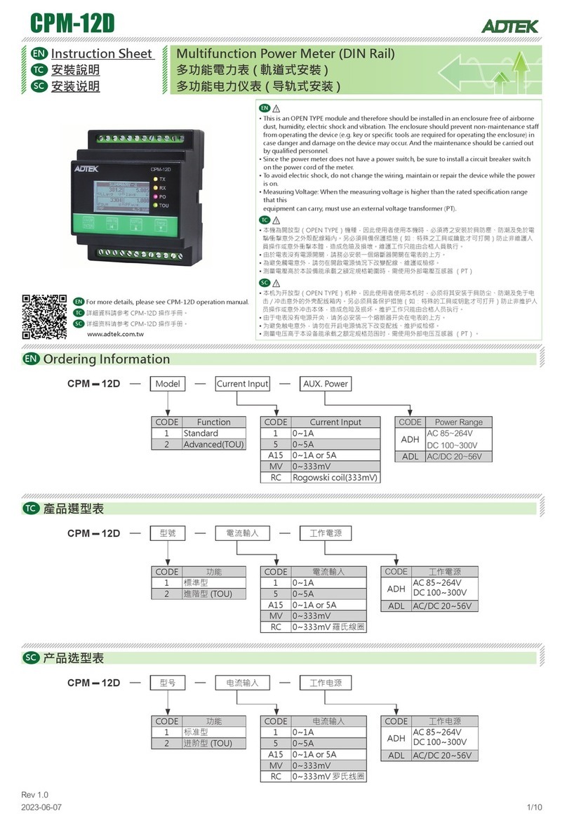
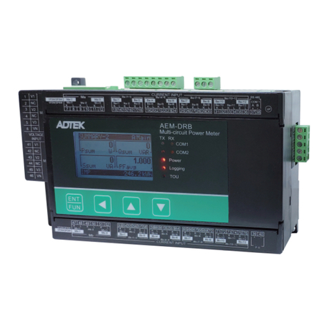
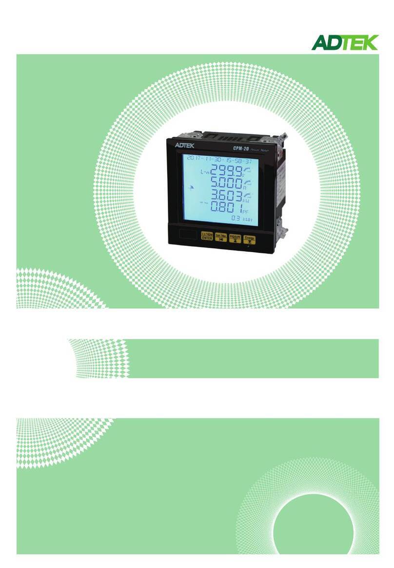
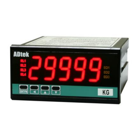
ADTEK CPM-10 User manual

CPM-10 Economical Multifunction Power Meter
Operation manual
Rev1.2
2017-04
End terminal ohm
A89:;<= -1,/>?@!"ABC.DEBCAFG.1!
"3)FGHIJKP4W.3
!"1 2 ),1-10~1-27LMNFGP W
!"1),1-14/1-1 ~ LMNFGP3W 6 27
!"3),1-1 1-1 /1-1 1- /P3W.1 3~ 5 7/1-18/ 20 1-21/1-23/1-24/1-
26/1-27LMNFG
!"3),1-1 1- /1- LMNFGP3W.2 7/ 20 23/1-26
!"3),1-1 1- /1- LMNFGP3W.3 7/ 20 23/1-26
!"3),1-1 1- /1-P4W.1 4~15/17~18 20~21/1-23~24/1-26~27
LMNFG
!"#$:1p2w 1p3w 3p3w.1 3p3w.2 3p3w.3/ / / / /
3p4w.1 3p4w.3/
!"#$%&:
v a v g.'()*+,-:
i a v g.'().+,-:
freq :/012-
p . t l :'(340-
q . t l :'(3540-
s . t l :'(36740-
pf.avg:'(+,408
$12-
v a :()*-12A
vb :B()*-12
vc :C()*-12
ia :A().-12
ib :B().-12
ic :C().-12
pf-a :A(4012-
pf-b :B(4012-
pf-c :C(4012-
p-a :A(4012-
p-b :B(4012-
p-c :C(4012-
q-a :A(54012-
q-b :B(54012-
q-c :C(54012-
s-a :A(674012
s-b :B(674012
s-c :C(674012
RELAY / PULSE output of the outputs can
only choose a functional output
EX: Select PULSE output and then RELAY
function no output and vice versa
Clamp CT
Optional of Clamp CT, make sure
(1)CT of the SN number with the
CPM-10 SN number, as shown
( )2 On the label A A Phase B B: -; : -
Phase C C Phase; : -;
According to the phase matching
Relay Pulse output
CL
BK
AK AL BL CK
, ,%&'(CT) *+,-./0 123456

DESCRIPTION
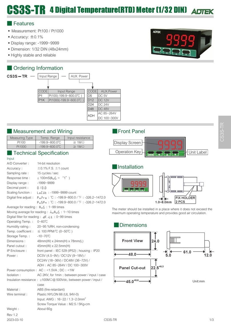
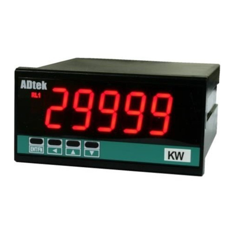
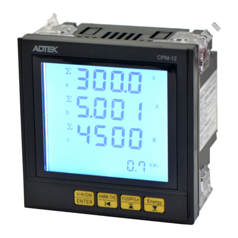
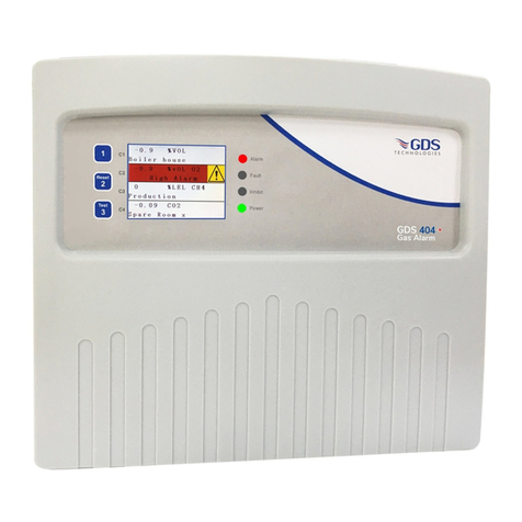
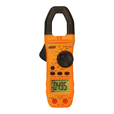
CPM-10 Multifunction meter product single phase, three
phases high accuracy measurement of parameters such as
voltage, current, active power, reactive power, apparent
power, power factor, frequency, effective energy, with display
and remote communication function. Option 1 set relay output,
1 analogue and 1 RS485 (Modbus RTU Mode) or 1 pulse output.
Most suitable for power management, remote input/output,
alarm and remote signal control uses needs. Having case
depth 120mm only, easy panel mounting installation.。
FEATURE
Input 1P2W,1P3W,3P3W,3P4W Unbalanced or balanced load system's active power,
reactive power, apparent power and electric energy (Watts-Hr) etc parameters.
Dual display, upper row 4 digits for voltage/ 4 digits for current ( or 10 digits Watts-Hr),lower
row 4 1/2 digits Watts.
1 set relay(SPDT) output, with 3 variable setting (R1.1/R1.2/R1.3), each react to setting
parameters V.AVG/I.AVG/FREQ/P.TL/Q.TL/ S.TL / PF.AVG / AE.TL / RE.TL / VA / VB / VC / IA /
IB / IC / PF-A / PF-B / PF-C / P-A / P-B / P-C / Q-A / Q-B / Q-C / S-A / S-B / S-C, having relay
function : Hi / Lo / Hi Hold / Lo H F; further advance function , start delay, hysteresis,old / OF
time delay, reset delay etc
1 analogues output same as relay setting parameters.
Output range: Current 0~10mA / 0~20 mA / 4~20 mA / 4~±20 mA / ±10 mA / ±20 mA
(Default 4-20mA)
Output range: Voltage 0~5V / 1~5 V / 0~10 V / 0~±5 V / 1~±5 V / 0~±10 V / ±5 V / ±10 V
(Default 0-10V)
Option pulse and RS 485 communication output.
Application
Motor control/ panel power monitoring/power consumption monitor and control/power distribution
system /intelligent building & automation power management system/ power testing equipment
The CPM-10 system (SCADA) monitoring as a power front-end measurement unit, for
volume measurement and control of remote power. Industry-standard RS-485
communication interface and MODBUS protocol, making connecting to the network easily
convenient, want to choose the management of the SCADA system.。
1/24
ENT/FN
AWHPLS
COM
WM K
KV VRL1
ENT/FN
AWHPLS
COM
WM K
KV VRL1
active energy
LED display
Relay/ Pulse
Control button
Active power (Watt)
LED display
Low row:
Watt display
Voltage unit
KV V, LED
Up row:
Left-V Right-A
or active energy
Rs485 Status
Front panel and button
output LED
CPM-10 Economical Multifunction Power Meter
End terminal ohm
A89:;<= -1,/>?@!"ABC.DEBCAFG.1!
"3)FGHIJKP4W.3
!"1 2 ),1-10~1-27LMNFGP W
!"1),1-14/1-1 ~ LMNFGP3W 6 27
!"3),1-1 1-1 /1-1 1- /P3W.1 3~ 5 7/1-18/ 20 1-21/1-23/1-24/1-
26/1-27LMNFG
!"3),1-1 1- /1- LMNFGP3W.2 7/ 20 23/1-26
!"3),1-1 1- /1- LMNFGP3W.3 7/ 20 23/1-26
!"3),1-1 1- /1-P4W.1 4~15/ 17~18 20~21/1-23~24/1-26~27
LMNFG
!"#$:1p2w 1p3w 3p3w.1 3p3w.2 3p3w.3/ / / / /
3p4w.1 3p4w.3/
!"#$%&:
v a v g.'()*+,-:
i a v g.'().+,-:
freq :/012-
p . t l :'(340-
q . t l :'(3540-
s . t l :'(36740-
pf.avg:'(+,408
$12-
v a :()*-12A
vb :B()*-12
vc :C()*-12
ia :A().-12
ib :B().-12
ic :C().-12
pf-a :A(4012-
pf-b :B(4012-
pf-c :C(4012-
p-a :A(4012-
p-b :B(4012-
p-c :C(4012-
q-a :A(54012-
q-b :B(54012-
q-c :C(54012-
s-a :A(674012
s-b :B(674012
s-c :C(674012
RELAY / PULSE output of the outputs can
only choose a functional output
EX: Select PULSE output and then RELAY
function no output and vice versa
Clamp CT
Optional of Clamp CT, make sure
(1)CT of the SN number with the
CPM-10 SN number, as shown
( )2 On the label A A Phase B B: - ; : -
Phase C C Phase; : - ;
According to the phase matching
Relay Pulse output
CL
BK
AK AL BL CK
, ,%&'(CT) *+,-./0 123456

4Control buttonEnter / Shift / Up / Down
Up key: Increase /back to previous
Down key: Decrease /to next
Shift key: Change decimal/back to previous
or escape setting
Enter/Fun key: Enter setting/save changes and
enter next parameters
P L S
COM
RL1
Display digits
Operation button
LED status
Pulse output: 1 rectangular red LED , when
pulse output LED blink;blink
faster mean more active energy
used.
RS 485 Com. rectangular orange LED when: 1 ,
Rs send receive data LED485 / ,
blink´blink faster mean data
transfer
Relay: 1 rectangular red LED,LED light
when relay energized ECI input
PV values 5 digits 0.28 0.71cm red LED: ; ”( )
Accumulative values 10 digits 0.28 cm; ”(0.71 )
K V
WH
LED Unit
Voltage unit LED rectangular red LED indicate:2
KV or V ,on when display select V-A
Watt unit LED Rectangular green LED , on when:3
display select KWH, automatic
switch KW or MW units
active energy LED rectangular red LED, on: 1
when select KWH display , only
display WH, K/M unit follow Watt.
Current unit LED rectangular red LED, on when:1
select display V-A
V
A
M
K
W
Installation
Dimension
This meter is installed does not exceed the maximum
operating temperature and humidity environment.
Output wiring
CL
BK
AK AL BL CK
Please check if the voltage is correct and connect to the right terminal number when wiring
CL
BK
AK AL BL CK
CL
BK
AK AL BL CK
CL
BK
AK AL BL CK
2 24/
Unit: mm
S i z e 9 6 m m x 4 8 m m x 1 2 0 m m:
48.0
Front
Cut size 4 4 . 0 +0.2
9 2 . 0 +0.2
9 6 . 0 1 0 0 . 0
8.0 12.0
C u t s i z e : 2 49 m m x 4 mm
+0.2 +0.2
1.0 ~8.0 mm
FIX HOLDER:
1 04 mm(L ) / W M3
PANEL CUT-OUT:
92+0.2(W) x 44+0. 2(H) mm
ENT/
FN
?
R L
1
R L
2
EC
I 1
E C
I 2
k
w
h
M
K
k
w
W
?
W
H
1Phase 3 wire
Output
AO RS485
Output
If no PT please direct input
to terminal
source
Relay output Aux
Load
Output
AO RS485
Output
If no PT please direct input
to terminal
Relay output
Aux
source
Load
If no PT please direct input
to terminal
Aux
Aux
Relay output
Output
AO RS485
Output
If no PT please direct input
to terminal
source
Load
Output
AO RS485
Output
3Phase 3wire 3CT (Unbalanced)
1Phase 2 wire
source
Load
3Phase 3wire 2CT (Unbalanced)
Relay output
With CLAMP CT, the secondary side do not ground or parallel connection, otherwise the meter burned■
With CLAMP CT, the secondary side do not ground or parallel connection, otherwise the meter burned■
End terminal ohm
A89:;<= -1,/>?@!"ABC.DEBCAFG.1!
"3)FGHIJKP4W.3
!"1 2 ),1-10~1-27LMNFGP W
!"1),1-14/1-1 ~ LMNFGP3W 6 27
!"3),1-1 1-1 /1-1 1- /P3W.1 3~ 5 7/1-18/ 20 1-21/1-23/1-24/1-
26/1-27LMNFG
!"3),1-1 1- /1- LMNFGP3W.2 7/ 20 23/1-26
!"3),1-1 1- /1- LMNFGP3W.3 7/ 20 23/1-26
!"3),1-1 1- /1-P4W.1 4~15/ 17~18 20~21/1-23~24/1-26~27
LMNFG
!"#$:1p2w 1p3w 3p3w.1 3p3w.2 3p3w.3/ / / / /
3p4w.1 3p4w.3/
!"#$%&:
v a v g.'()*+,-:
i a v g.'().+,-:
freq :/012-
p . t l :'(340-
q . t l :'(3540-
s . t l :'(36740-
pf.avg:'(+,408
$12-
v a :()*-12A
vb :B()*-12
vc :C()*-12
ia :A().-12
ib :B().-12
ic :C().-12
pf-a :A(4012-
pf-b :B(4012-
pf-c :C(4012-
p-a :A(4012-
p-b :B(4012-
p-c :C(4012-
q-a :A(54012-
q-b :B(54012-
q-c :C(54012-
s-a :A(674012
s-b :B(674012
s-c :C(674012
RELAY / PULSE output of the outputs can
only choose a functional output
EX: Select PULSE output and then RELAY
function no output and vice versa
Clamp CT
Optional of Clamp CT, make sure
(1)CT of the SN number with the
CPM-10 SN number, as shown
( )2 On the label A A Phase B B: - ; : -
Phase C C Phase; : - ;
According to the phase matching
Relay Pulse output
CL
BK
AK AL BL CK
, ,%&'(CT) *+,-./0 123456

CL
BK
AK AL BL CK
CL
BK
AK AL BL CK
CL
BK
AK AL BL CK
3 24/
When wiring, be sure to confirm that the supply voltage is correct and access the correct
terminal number.
Equipment and instrumentation safety, it is recommended to install the fuse or no fuse switch in
the instrument before。
If no PT please direct input
to terminal
source
Aux
Load
Relay output
Output
AO RS485
Output
3Phase 4wire 1CT (Balanced)
3Phase 3wire 1CT (Balanced)
Output
AO RS485
Output
Relay output
If no PT please direct input
to terminal
source
Load
3Phase 4wire 3CT (Unbalanced)
Output
AO RS485
Output
If no PT please direct input
to terminal
source
Load
Relay output Aux
Output wiring
CL
BK
AK AL BL CK
Clamp CT
Optional of Clamp CT, make sure
(1)CT of the SN number with the CPM-10 SN number, as
shown
(2)On the label A:A-Phase; B:B-Phase ; C:C-Phase ;
According to the phase matching
(3)S1 (white) connected” K” side;
S2 (black)connected “L” side
(A.B.C Phase are the same then the law)
s2
s1
Direction of the arrow
indicates the direction
for the primary current
through P1-P2
P2
P1 P1
P1
P2
P2
With CLAMP CT, the secondary side do not ground or parallel connection, otherwise the meter burned■
CL
BK
AK AL BL CK
Output
AO RS485
Output
source
Load
Relay output Aux
Note■
With CLAMP CT, the secondary side do not ground or parallel
connection, otherwise the meter burned
End terminal ohm
A89:;<= -1,/>?@!"ABC.DEBCAFG.1!
"3)FGHIJKP4W.3
!"1 2 ),1-10~1-27LMNFGP W
!"1),1-14/1-1 ~ LMNFGP3W 6 27
!"3),1-1 1-1 /1-1 1- /P3W.1 3~ 5 7/1-18/ 20 1-21/1-23/1-24/1-
26/1-27LMNFG
!"3),1-1 1- /1- LMNFGP3W.2 7/ 20 23/1-26
!"3),1-1 1- /1- LMNFGP3W.3 7/ 20 23/1-26
!"3),1-1 1- /1-P4W.1 4~15/ 17~18 20~21/1-23~24/1-26~27
LMNFG
!"#$:1p2w 1p3w 3p3w.1 3p3w.2 3p3w.3/ / / / /
3p4w.1 3p4w.3/
!"#$%&:
v a v g.'()*+,-:
i a v g.'().+,-:
freq :/012-
p . t l :'(340-
q . t l :'(3540-
s . t l :'(36740-
pf.avg:'(+,408
$12-
v a :()*-12A
vb :B()*-12
vc :C()*-12
ia :A().-12
ib :B().-12
ic :C().-12
pf-a :A(4012-
pf-b :B(4012-
pf-c :C(4012-
p-a :A(4012-
p-b :B(4012-
p-c :C(4012-
q-a :A(54012-
q-b :B(54012-
q-c :C(54012-
s-a :A(674012
s-b :B(674012
s-c :C(674012
RELAY / PULSE output of the outputs can
only choose a functional output
EX: Select PULSE output and then RELAY
function no output and vice versa
Clamp CT
Optional of Clamp CT, make sure
(1)CT of the SN number with the
CPM-10 SN number, as shown
( )2 On the label A A Phase B B: - ; : -
Phase C C Phase; : - ;
According to the phase matching
Relay Pulse output
CL
BK
AK AL BL CK
, ,%&'(CT) *+,-./0 123456

J2
J3
TOP PANEL
11 12 13 16
15
14
30V/60mA
CSM-
V mA
78 9 10
L
N
G
L
N
G
1A
ADH:AC85~264V
DC100~300V
ADL:AC/DC 20~65V
A1~A16: 20A/600Vac, M3.5, 22~12AWG;
13Kg-cm
:10A 300Vac, M2.6, 22~16AWG,
: 5Kg-cm
7.0mm max
7.0mm max
2.0mm max
Voltage/Current
16
16
B
A
16
B
A
J2
J3
J2
J3
4 24/
Analogue output
Wire terminal Analogue output
Terminal:
Max Torque:
Output Terminal
Max Torque
Please use flat Pin
AUX
Fuse
Transformer filter
Pulse output
Due to limitation on number of terminal , pulse and relay
output is having same terminal, choose either one
Open collector:(OPC1)
Max load
RS Com485 .
Please earth isolation net to maintain signal quality
Wire distance: 1200M
:
120~300 ohm/0.25W
(typical: 150ohm)
End terminal ohm
Output mode: Selectable
within parameters setting,
voltage or current output need
to short J2 & J3 on output PCB
module.
Analogue output
points
Output short
:Current
:Voltage
Analogue + RS485
Voltage/Current
5A/230V 5A/115V,
COM NC
5 6 7
NO
Relay Pulse output OPR1:( )
Contact:
5A/230V 5A/115V,
COM NC
5 6 7
NO
Contact:
Alarm Relay output:(OR1)
Action frequency
less than 30HZ
5 6 7
E-C+
End terminal ohm
ADEFGHI -1,:JKL)*MNO.PQNOMRS.<)
*34RSTUVWP4W.3
)*1 2 4,1-10~1-27XYZRSP W
)*14,1-14/1-1 ~ XYZRSP3W 6 27
)*34,1-1 1-1 /1-1 1- /P3W.1 3~ 5 7/1-18/ 20 1-21/1-23/1-24/1-
26/1-27XYZRS
)*34,1-1 1- /1- XYZRSP3W.2 7/ 20 23/1-26
)*34,1-1 1- /1- XYZRSP3W.3 7/ 20 23/1-26
)*34,1-1 1- /1-P4W.1 4~15/ 17~18 20~21/1-23~24/1-26~27
XYZRS
)*+,:1p2w 1p3w 3p3w.1 3p3w.2 3p3w.3/ / / / /
3p4w.1 3p4w.3/
"#$%&':
v a v g.()*+,-.:
i a v g.()*/,-.:
freq :2345.
p . t l :()673.
q . t l :()6873.
s . t l :()69:73.
pf.avg:(),-73;
%45.
v a :)*+.45A
vb :B)*+.45
vc :C)*+.45
ia :A)*/.45
ib :B)*/.45
ic :C)*/.45
pf-a :A)7345.
pf-b :B)7345.
pf-c :C)7345.
p-a :A)7345.
p-b :B)7345.
p-c :C)7345.
q-a :A)87345.
q-b :B)87345.
q-c :C)87345.
s-a :A)9:7345
s-b :B)9:7345
s-c :C)9:7345
RELAY / PULSE output of the outputs can
only choose a functional output
EX: Select PULSE output and then RELAY
function no output and vice versa
Clamp CT
Optional of Clamp CT, make sure
(1)CT of the SN number with the
CPM-10 SN number, as shown
( )2 On the label A A Phase B B: - ; : -
Phase C C Phase; : - ;
According to the phase matching
Relay Pulse output
CL
BK
AK AL BL CK
, ,0123CT4 56789:; <=>?@A

Parameter setting(A-1),connection different.will have
a different display(tick shown)
Hold escape to measuring page
■Operation flow chart:
U V W # X Y
Measuring page
Press
Hold 1S
r 1 @ s p
Relay 1.2 setting point
0-2
r 1 # s p
Relay 1.3 setting point
0-3
rYrst
Reset relay
0-4
Relay 1.1 setting point
r 1 ! s p
0-1
v e r ! 3
cpm-10
Version Model
0-5
Check wiring
before power up
** * * * *
** * * * *
3 p 3 w
c p m - 1 0
ver1.0
If no relay functions
Will only display
version and model
2 2 ) 0 1 0 ) 0
) 0
) 0
) 0
At 1-28 display function , choose V-A ( voltage/current)
,display as left, during KWH selection.
W
Self test
(LED all on) Wire type
Model
Software
To relay setting
VA
W Hr
/
W
diSsl
1-28
q - c
1-24
s-a
1-25
s-b
1-26
s-c
1-27
u-b
1-11
Uavg
1-1
I a v g
1-2
freq
1-3
Ptl
1-4
Qtl
1-5
Stl
1-6
pFavg
1-7
aEtl
1-8
rEtl
1-9
u - a
1-10
u - c
1-12
I - a
1-13
I - b
1-14
I-c
1-15
p f - a
1-16
p f - b
1-17
p f - c
1-18
p-a
1-19
p - b
1-20
p - c
1-21
q - a
1-22
q - b
1-23
Back
to1-1
5 24/
3 Phase average
voltage 3 Phase
average current
Frequency 3 Phase active
power
3 Phase reactive
power
3 Phase
apparent power
3 Phase average
power factor
3 Phase total active
energy 3 Phase total
reactive energy Phase A voltage
Phase B voltage Phase C voltage Phase A current Phase B current Phase C current
Phase A power factor Phase B power factor Phase C power factor Phase A active
power
Phase B
active power
Phase C active
power
Phase A reactive
power
Phase B
reactive power
Phase C
reactive power
Phase A apparent
power
Phase B apparent
power Phase C apparent power Unit
V-A/KWH
End terminal ohm
ADEFGHI -1,:JKL)*MNO.PQNOMRS.<)
*34RSTUVWP4W.3
)*1 2 4,1-10~1-27XYZRSP W
)*14,1-14/1-1 ~ XYZRSP3W 6 27
)*34,1-1 1-1 /1-1 1- /P3W.1 3~ 5 7/1-18/ 20 1-21/1-23/1-24/1-
26/1-27XYZRS
)*34,1-1 1- /1- XYZRSP3W.2 7/ 20 23/1-26
)*34,1-1 1- /1- XYZRSP3W.3 7/ 20 23/1-26
)*34,1-1 1- /1-P4W.1 4~15/ 17~18 20~21/1-23~24/1-26~27
XYZRS
)*+,:1p2w 1p3w 3p3w.1 3p3w.2 3p3w.3/ / / / /
3p4w.1 3p4w.3/
"#$%&':
v a v g.()*+,-.:
i a v g.()*/,-.:
freq :2345.
p . t l :()673.
q . t l :()6873.
s . t l :()69:73.
pf.avg:(),-73;
%45.
v a :)*+.45A
vb :B)*+.45
vc :C)*+.45
ia :A)*/.45
ib :B)*/.45
ic :C)*/.45
pf-a :A)7345.
pf-b :B)7345.
pf-c :C)7345.
p-a :A)7345.
p-b :B)7345.
p-c :C)7345.
q-a :A)87345.
q-b :B)87345.
q-c :C)87345.
s-a :A)9:7345
s-b :B)9:7345
s-c :C)9:7345
RELAY / PULSE output of the outputs can
only choose a functional output
EX: Select PULSE output and then RELAY
function no output and vice versa
Clamp CT
Optional of Clamp CT, make sure
(1)CT of the SN number with the
CPM-10 SN number, as shown
( )2 On the label A A Phase B B: - ; : -
Phase C C Phase; : - ;
According to the phase matching
Relay Pulse output
CL
BK
AK AL BL CK
, ,0123CT4 56789:; <=>?@A

group
pulse
group
rs485
group
a o
RELAY
GROUP
group
relay
INPUT
GROUP
group
input
enter
Pcode
NO
YES
ENT
P
p T p r i
5 0 ) 0
A-3
cTSEC
% 0 0 0
A-6
a v g - u
5
A-7
avg-p
5
A-9
ENT
P1S back
2 2 ) 0 1 0 ) 0
) 0
ANALOGUE
OUTPUT
GROUP
RS485
GROUP
PULSE
GROUP
U u n i t
v
A-2
wires
3p3W3
A-1
p T s e c
5 0 ) 0
A-4
cTPRI
5)0
A-5
avg-I
5
A-8
1S back
ENT
P
Wiring 1P2W / 1P3W/3P3W.1 / 3P3W.2/:
A-6
INPUT
GROUP
group
input
Primary PT unit V KV: /
A-7
A-2
Primary PT voltage 0V~ KV50. 100
Secondary PTvoltage 0V~ V50. 500
A-3
Primary CT current 0A A1. ~2999.9
A-4
Secondary CT current 1A/5A
Voltage average value Range: 2~99
Current average value Range: 2~99
Active power average Range: 2~99
Change P. code: 0000~9999
Function lock NONE/USER/ENG/ALL:
Reset active/reactive energy: 0~9999
A-5
A-1A-1
A-14
A-8
A-9
A-12
A-13
Parameter Description
Index Explain
6 24/
Engineer level
Password
P.code
Correct
Default:1000
PV value
V A
W
Wire type Primary PT unit V KV: / Primary PT voltage
50 100V~ KV
Secondary PTvoltage
50 500V~ V
Primary CT current Secondary CT
current Voltage
average value Current average value
Active power
average
tLrst
0 0 0 0
A-12
Reset active
energy/reactive energy
Pcode
1 0 0 0
A-13
Change P. code
F l o c y
n o n e
A-14
Function lock
Press sec escape to measuring page1
Index Explain
w - d i v
Watt high-resolution:
OFF:0(Normal)
ON:1(High)
o f f
A-10
lOcut
Low Cut:
0.0~100.0%
) 2
A-11
End terminal ohm
ADEFGHI -1,:JKL)*MNO.PQNOMRS.<)
*34RSTUVWP4W.3
)*1 2 4,1-10~1-27XYZRSP W
)*14,1-14/1-1 ~ XYZRSP3W 6 27
)*34,1-1 1-1 /1-1 1- /P3W.1 3~ 5 7/1-18/ 20 1-21/1-23/1-24/1-
26/1-27XYZRS
)*34,1-1 1- /1- XYZRSP3W.2 7/ 20 23/1-26
)*34,1-1 1- /1- XYZRSP3W.3 7/ 20 23/1-26
)*34,1-1 1- /1-P4W.1 4~15/ 17~18 20~21/1-23~24/1-26~27
XYZRS
)*+,:1p2w 1p3w 3p3w.1 3p3w.2 3p3w.3/ / / / /
3p4w.1 3p4w.3/
"#$%&':
v a v g.()*+,-.:
i a v g.()*/,-.:
freq :2345.
p . t l :()673.
q . t l :()6873.
s . t l :()69:73.
pf.avg:(),-73;
%45.
v a :)*+.45A
vb :B)*+.45
vc :C)*+.45
ia :A)*/.45
ib :B)*/.45
ic :C)*/.45
pf-a :A)7345.
pf-b :B)7345.
pf-c :C)7345.
p-a :A)7345.
p-b :B)7345.
p-c :C)7345.
q-a :A)87345.
q-b :B)87345.
q-c :C)87345.
s-a :A)9:7345
s-b :B)9:7345
s-c :C)9:7345
RELAY / PULSE output of the outputs can
only choose a functional output
EX: Select PULSE output and then RELAY
function no output and vice versa
Clamp CT
Optional of Clamp CT, make sure
(1)CT of the SN number with the
CPM-10 SN number, as shown
( )2 On the label A A Phase B B: - ; : -
Phase C C Phase; : - ;
According to the phase matching
Relay Pulse output
CL
BK
AK AL BL CK
, ,0123CT4 56789:; <=>?@A

RELAY
GROUP
group
r e l a y U a v g
r!!sl
B-1
Relay R1.1
parameters:
off
r!!md
Relay R1.1
mode:
B-2
3 0 ) 0
r!!sp
B-3
Relay R1.2 parameters
same as.2 R1.1
B-4
Iavg
r!@sl
l o
r!@md
Relay R1.2 mode:
B-5
2 % 0 0
r!@sp
Relay R1.2 set point
B-6
o f f
r!#md
Relay R1.3
mode:
B-8
f r e q
r!#sl
Relay R1.3 parameters same
as R1.1
B-7
4 % 0 0
r!#sp
Relay R1.3 set point:
B-9
advnc
p r o g
Program:
BASIC backto B-1/
ADVNC down toB-11
B-10
) 0 0
r ! ! s b
Relay R1.1
start band
B-11
) 0 ) 0
r!!sd
Relay R1.1 start
delay
B-12
) 0 0
r!!hy
Relay R1.1
hysteris:
B-13
) 0 ) 0
r!!rd
Relay R1.1 delay
energize:
B-14
) 0 ) 0
r!!fd
Relay R1.1 delay
deenergize:
B-15
)00
r!@sb
Relay R1.2 start
band
B-16
) 0 ) 0
r!@sd
Relay R1.2 start
delay
B-17
)00
r!@hy
Relay R1.2
hysteris:
B-18
) 0 ) 0
r!@rd
Relay R1.2 delay
energize:
B-19
) 0 ) 0
r!@fd
Relay R1.2 delay de-
energize:
B-20
)00
r ! # s b
Relay R1.3 start
band
B-21
) 0 ) 0
r!#sd
Relay R1.3
start band
B-22
)00
r!#hy
Relay R1.3
start delay
B-23
) 0 ) 0
r!#rd
Relay R1.3 delay
energize
B-24
) 0 ) 0
r!#fd
Relay R1.3 delay de-
energize:
B-25
B-7
B-1
B-4
7 24/
Engineer level
group
pulse
group
rs485
group
a o
RELAY
GROUP
group
relay
enter
Pcode
NO
YES
ENT
P
ENT
P1S back
2 2 ) 0 1 0 ) 0
) 0
ANALOGUE
OUTPUT
GROUP
RS485
GROUP
PULSE
GROUP
INPUT
GROUP
group
input
Password
P.code
Correct
Default:1000
PV value
V A
W
1S back
ENT
P
Relay R1.1 set
point:
Press 1 sec escape to measuring page
Parameter Description
Explain
Index
Parameter settings:
v a v g. :3 Phase average voltage
i a v g. :3 Phase apparent power
freq :Frequency
p . t l :3 Phase active power
q . t l :3 Phase reactive power
s . t l :3 Phase apparent power
p f . a v g :3 Phase average power factor
v a :Phase A voltage
v b :Phase B voltage
v c :Phase voltageC
i a :Phase A current
i b :Phase currentB
i c :Phase currentC
Parameter settings:
p f - a :Phase A power factor
p f - b :Phase B power factor
p f - c :Phase C power factor
p - a :Phase A active power
p - b :Phase B active power
p - c :Phase C active power
q - a :Phase A reactive power
q - b :Phase B reactive power
q - c :Phase C reactive power
s - a :Phase A apparent power
s - b :Phase B apparent power
s - c :Phase C apparent power
End terminal ohm
ADEFGHI -1,:JKL)*MNO.PQNOMRS.<)
*34RSTUVWP4W.3
)*1 2 4,1-10~1-27XYZRSP W
)*14,1-14/1-1 ~ XYZRSP3W 6 27
)*34,1-1 1-1 /1-1 1- /P3W.1 3~ 5 7/1-18/ 20 1-21/1-23/1-24/1-
26/1-27XYZRS
)*34,1-1 1- /1- XYZRSP3W.2 7/ 20 23/1-26
)*34,1-1 1- /1- XYZRSP3W.3 7/ 20 23/1-26
)*34,1-1 1- /1-P4W.1 4~15/ 17~18 20~21/1-23~24/1-26~27
XYZRS
)*+,:1p2w 1p3w 3p3w.1 3p3w.2 3p3w.3/ / / / /
3p4w.1 3p4w.3/
"#$%&':
v a v g.()*+,-.:
i a v g.()*/,-.:
freq :2345.
p . t l :()673.
q . t l :()6873.
s . t l :()69:73.
pf.avg:(),-73;
%45.
v a :)*+.45A
vb :B)*+.45
vc :C)*+.45
ia :A)*/.45
ib :B)*/.45
ic :C)*/.45
pf-a :A)7345.
pf-b :B)7345.
pf-c :C)7345.
p-a :A)7345.
p-b :B)7345.
p-c :C)7345.
q-a :A)87345.
q-b :B)87345.
q-c :C)87345.
s-a :A)9:7345
s-b :B)9:7345
s-c :C)9:7345
RELAY / PULSE output of the outputs can
only choose a functional output
EX: Select PULSE output and then RELAY
function no output and vice versa
Clamp CT
Optional of Clamp CT, make sure
(1)CT of the SN number with the
CPM-10 SN number, as shown
( )2 On the label A A Phase B B: - ; : -
Phase C C Phase; : - ;
According to the phase matching
Relay Pulse output
CL
BK
AK AL BL CK
, ,0123CT4 56789:; <=>?@A

Lo(Low Level Energized):
When the displayed value is lower than the set value
(PV <Set point), the relay action。
Hi(High Level Energized):
When the displayed value is higher than the set value
(PV> Set point), the relay action。
Lo.hld:
(Low Level energized hold Displayed value lower):
than set value action, and continued to maintain
action.
HI.HLD:
(High Level energized hold Displayed value higher):
than the set value, the action, and continued to
maintain action.。
off(Turn off the Relay):Close relay function when,
relay is off, relay remain open, LED will not
light。
B-8
B-2
B-5
Relay mode LO/HI/LO.HLD/:
HI.HLD/OFF
B-9
B-3
B-6
Relay set point range:
-199.99~299.99
B-11
B-16
B-21
Relay start band 0 00 99.99 (count): . ~
Relay start delay times:
0.00.00~9.59.9( / / . )min sec 0 1s
B-12
B-17
B-22
B-13
B-18
B-23
Relay hysteris 0 00 0 (count): . ~50 0.
B-14
B-19
B-24
Relay delay energize:
0.00.0~9.59.9( / / . )min sec 0 1s
B-15
B-20
B-25
Relay delay de-energize:
0.00.0~9.59.9( / / . )min sec 0 1s
group
a o
ANALOGUE
OUTPUT
GROUP
1S back
ENT
P
I a v g
a)sl
Analogue output
parameter
C-1
A4-20
aOtp
Analogue output
type and range:
C-2
)00
a O l s
Analogue output low-
scale
C-3
5 ) 0 0
a O h s
Analogue output hi-
scale:
C-4
)00
aOzo
Analogue output low
fine tunning:
C-5
)00
a O s n
Analogue output Hi
fine tunning:
C-6
Psclr
Reset fine tunning:
n o n e
C-7
11)00
aOlt
Output limit:
C-8
8 24/
Engineer level
Parameter Description
Explain
Index
group
pulse
group
rs485
group
a o
RELAY
GROUP
group
relay
enter
Pcode
NO
YES
ENT
P
ENT
P1S back
2 2 ) 0 1 0 ) 0
) 0
ANALOGUE
OUTPUT
GROUP
RS485
GROUP
PULSE
GROUP
INPUT
GROUP
group
input
Password
P.code
Correct
Default:1000
PV value
V A
W
Press sec escape to measuring page1
Engineer level
End terminal ohm
ADEFGHI -1,:JKL)*MNO.PQNOMRS.<)
*34RSTUVWP4W.3
)*1 2 4,1-10~1-27XYZRSP W
)*14,1-14/1-1 ~ XYZRSP3W 6 27
)*34,1-1 1-1 /1-1 1- /P3W.1 3~ 5 7/1-18/ 20 1-21/1-23/1-24/1-
26/1-27XYZRS
)*34,1-1 1- /1- XYZRSP3W.2 7/ 20 23/1-26
)*34,1-1 1- /1- XYZRSP3W.3 7/ 20 23/1-26
)*34,1-1 1- /1-P4W.1 4~15/ 17~18 20~21/1-23~24/1-26~27
XYZRS
)*+,:1p2w 1p3w 3p3w.1 3p3w.2 3p3w.3/ / / / /
3p4w.1 3p4w.3/
"#$%&':
v a v g.()*+,-.:
i a v g.()*/,-.:
freq :2345.
p . t l :()673.
q . t l :()6873.
s . t l :()69:73.
pf.avg:(),-73;
%45.
v a :)*+.45A
vb :B)*+.45
vc :C)*+.45
ia :A)*/.45
ib :B)*/.45
ic :C)*/.45
pf-a :A)7345.
pf-b :B)7345.
pf-c :C)7345.
p-a :A)7345.
p-b :B)7345.
p-c :C)7345.
q-a :A)87345.
q-b :B)87345.
q-c :C)87345.
s-a :A)9:7345
s-b :B)9:7345
s-c :C)9:7345
RELAY / PULSE output of the outputs can
only choose a functional output
EX: Select PULSE output and then RELAY
function no output and vice versa
Clamp CT
Optional of Clamp CT, make sure
(1)CT of the SN number with the
CPM-10 SN number, as shown
( )2 On the label A A Phase B B: - ; : -
Phase C C Phase; : - ;
According to the phase matching
Relay Pulse output
CL
BK
AK AL BL CK
, ,0123CT4 56789:; <=>?@A

C-1
prity
Modbus paraity:
n.stb.1/n.stb.2/odd/even
NstB2
D-3
9600
b a u d
Modbus baud rate:
1200/2400/4800/9600/19
200/38400
D-2
1
adres
Address:
1~255
D-1
group
r s 4 8 5
RS485
GROUP 1S back
ENT
P
Current:
A0-10 mA A0-20: mA A 4-20 mA:0~10 0~20 . :4~20
A 4B20 mA Ab10 ± mA. :4~12~20 : 10
Ab20 ± mA: 20
Voltage:
V0-5:0~5V V1-5:1~5V V0-10:0~10V
V0B5:0~2.5~5V V1B5:1~3~5V
V0B10 V Vb5:± V Vb10:± V:0~5~10 5 10
C-2 Output signal of type and
range :
A A /A.0-10/ .0-20 .4-20/
A B /A B. A B /.4 .20 . 10/ . .20
V V. /V V B /.0-5/ 1-5 .0-10/ .0 .5
C-3 Analogue output low-scale:
-19999~29999
C-4 Analogue output hi-scale:
-19999~29999
C-5 Analogue output low fine
tunning::
C-6 Analogue output Hi fine tunning:
-32768~32767
C-7 Reset fine tunning:
NONE/AO ZRO AO SPN BOTH. / . /
none(NONE): Does not clear the correction
aOzro(Ao.Zro): Clear the lower limit of fine-tuning
aOspn(Ao.SPn): Clear upper limit of fine-tuning
both(both): Clear the lower limit, upper limit of fine-tuning
correction
C-8 Output limit:0~110 %
9 24/
Parameter Description
ExplainIndex
AO corresponding the parameters:
v a v g. :3 Phase average voltage
i a v g. :3 Phase apparent power
freq :Frequency
p . t l :3 Phase active power
q . t l :3 Phase reactive power
s . t l :3 Phase apparent power
p f . a v g :3 Phase average power factor
v a :Phase A voltage
v b :Phase B voltage
v c :Phase voltageC
i a :Phase A current
i b :Phase currentB
i c :Phase currentC
AO corresponding the parameters:
p f - a :Phase A power factor
p f - b :Phase B power factor
p f - c :Phase C power factor
p-a :Phase A active power
p-b :Phase B active power
p-c :Phase C active power
q-a :Phase A reactive power
q-b :Phase B reactive power
q-c :Phase C reactive power
s-a :Phase A apparent power
s-b :Phase B apparent power
s-c :Phase C apparent power
group
pulse
group
rs485
group
a o
RELAY
GROUP
group
relay
enter
Pcode
NO
YES
ENT
P
ENT
P1S back
2 2 ) 0 1 0 ) 0
) 0
ANALOGUE
OUTPUT
GROUP
RS485
GROUP
PULSE
GROUP
INPUT
GROUP
group
input
Password
P.code
Correct
Default:1000
PV value
V A
W
Engineer level
Press sec escape to measuring page1
End terminal ohm
ADEFGHI -1,:JKL)*MNO.PQNOMRS.<)
*34RSTUVWP4W.3
)*1 2 4,1-10~1-27XYZRSP W
)*14,1-14/1-1 ~ XYZRSP3W 6 27
)*34,1-1 1-1 /1-1 1- /P3W.1 3~ 5 7/1-18/ 20 1-21/1-23/1-24/1-
26/1-27XYZRS
)*34,1-1 1- /1- XYZRSP3W.2 7/ 20 23/1-26
)*34,1-1 1- /1- XYZRSP3W.3 7/ 20 23/1-26
)*34,1-1 1- /1-P4W.1 4~15/ 17~18 20~21/1-23~24/1-26~27
XYZRS
)*+,:1p2w 1p3w 3p3w.1 3p3w.2 3p3w.3/ / / / /
3p4w.1 3p4w.3/
"#$%&':
v a v g.()*+,-.:
i a v g.()*/,-.:
freq :2345.
p . t l :()673.
q . t l :()6873.
s . t l :()69:73.
pf.avg:(),-73;
%45.
v a :)*+.45A
vb :B)*+.45
vc :C)*+.45
ia :A)*/.45
ib :B)*/.45
ic :C)*/.45
pf-a :A)7345.
pf-b :B)7345.
pf-c :C)7345.
p-a :A)7345.
p-b :B)7345.
p-c :C)7345.
q-a :A)87345.
q-b :B)87345.
q-c :C)87345.
s-a :A)9:7345
s-b :B)9:7345
s-c :C)9:7345
RELAY / PULSE output of the outputs can
only choose a functional output
EX: Select PULSE output and then RELAY
function no output and vice versa
Clamp CT
Optional of Clamp CT, make sure
(1)CT of the SN number with the
CPM-10 SN number, as shown
( )2 On the label A A Phase B B: - ; : -
Phase C C Phase; : - ;
According to the phase matching
Relay Pulse output
CL
BK
AK AL BL CK
, ,0123CT4 56789:; <=>?@A

group
pulse
PULSE
GROUP
plSdu
1
E-1
E-2
p l S h i
auto
1S back
ENT
P
Pulse output/Count
setting:1~9999
Hi-voltage output
time AUTO:0( )~500
0
E-1
Pulse/Count High-potential
output time:
E-2
1 /0 24
group
pulse
group
rs485
group
a o
RELAY
GROUP
group
relay
enter
Pcode
NO
YES
ENT
P
ENT
P1S back
2 2 ) 0 1 0 ) 0
) 0
ANALOGUE
OUTPUT
GROUP
RS485
GROUP
PULSE
GROUP
INPUT
GROUP
group
input
Password
P.code
Correct
Default:1000
PV value
V A
W
Engineer level
Press sec escape to measuring page1
Parameter Description
ExplainIndex
※%;When set 0, mean Duty cycle.is 50 setting
1~5000(x4ms.) time length please beware at long,
time length, high frequency the output may remain at
H-voltage and not completing a full pulse cycle,
resulting data not readable.
※When set 1,mean 1 count watt hr give 1
pulse: When set 1000, mean 1000 count
watt hr give 1 pulse ,
RELAY / PULSE output of the outputs can
only choose a functional output
EX: Select PULSE output and then RELAY
function no output and vice versa
End terminal ohm
ADEFGHI -1,:JKL)*MNO.PQNOMRS.<)
*34RSTUVWP4W.3
)*1 2 4,1-10~1-27XYZRSP W
)*14,1-14/1-1 ~ XYZRSP3W 6 27
)*34,1-1 1-1 /1-1 1- /P3W.1 3~ 5 7/1-18/ 20 1-21/1-23/1-24/1-
26/1-27XYZRS
)*34,1-1 1- /1- XYZRSP3W.2 7/ 20 23/1-26
)*34,1-1 1- /1- XYZRSP3W.3 7/ 20 23/1-26
)*34,1-1 1- /1-P4W.1 4~15/ 17~18 20~21/1-23~24/1-26~27
XYZRS
)*+,:1p2w 1p3w 3p3w.1 3p3w.2 3p3w.3/ / / / /
3p4w.1 3p4w.3/
"#$%&':
v a v g.()*+,-.:
i a v g.()*/,-.:
freq :2345.
p . t l :()673.
q . t l :()6873.
s . t l :()69:73.
pf.avg:(),-73;
%45.
v a :)*+.45A
vb :B)*+.45
vc :C)*+.45
ia :A)*/.45
ib :B)*/.45
ic :C)*/.45
pf-a :A)7345.
pf-b :B)7345.
pf-c :C)7345.
p-a :A)7345.
p-b :B)7345.
p-c :C)7345.
q-a :A)87345.
q-b :B)87345.
q-c :C)87345.
s-a :A)9:7345
s-b :B)9:7345
s-c :C)9:7345
RELAY / PULSE output of the outputs can
only choose a functional output
EX: Select PULSE output and then RELAY
function no output and vice versa
Clamp CT
Optional of Clamp CT, make sure
(1)CT of the SN number with the
CPM-10 SN number, as shown
( )2 On the label A A Phase B B: - ; : -
Phase C C Phase; : - ;
According to the phase matching
Relay Pulse output
CL
BK
AK AL BL CK
, ,0123CT4 56789:; <=>?@A

Enter
DecreaseIncrease
Shift
2 2 ) 0 1 0 ) 0
) 0
) 0
) 0
1-28 selection, choose VA (voltage / current), display
as follows. Select KWH option is displayed at right
VA
WW
W/H
n o
r Y r s t
0-4
v e r ! 3
cpm-10
0-5
4 % 0 0
r 1 # s p
0-3
2 % 0 0
r 1 @ s p
0-2
3 ) 0 0
r 1 ! s p
0-1
Press 1Sec
User Level
■Operating Steps
Power on
Check the wiring
******
******
Self test
LED all on
3 p 4 w c p m - 1 0
ver1.3
Into the relay function
No need to set
Back to 0-1
There is no relay
functions
Will only display
version
1 241/
Parameters Display Setting Operation
Wiring Model
Version
Relay 1.1
funtion
setting
Relay R1.1 value
range:-199.99 299.99~
Press values blink press change value or selection, &
when done press to next setting or hold 1 sec
to previous selection list.
Enter
DecreaseIncrease
Shift
Press values blink press change value or selection, &
when done press to next setting or hold 1 sec
to previous selection list.
Enter
DecreaseIncrease
Shift
Press values blink press change value or selection, &
when done press to next setting or hold 1 sec
to previous selection list.
Enter
DecreaseIncrease
Shift
Press values blink press change value or selection, &
when done press to next setting or hold 1 sec
to previous selection list.
Relay R1.2 value
range 199 99 299 9
:- . .~9
Relay 1.2
funtion
setting
Relay 1.3
funtion
setting
Relay R1.3 value
range 199 9:- . .99 299 9~
Reset relay
function Select:yes no/
Version
Model View only
Pres s sec es c a p e t o be g i n in g p a ge .1
Pre s s s ec es c a pe to me a suri n g p age .1
End terminal ohm
ADEFGHI -1,:JKL)*MNO.PQNOMRS.<)
*34RSTUVWP4W.3
)*1 2 4,1-10~1-27XYZRSP W
)*14,1-14/1-1 ~ XYZRSP3W 6 27
)*34,1-1 1-1 /1-1 1- /P3W.1 3~ 5 7/1-18/ 20 1-21/1-23/1-24/1-
26/1-27XYZRS
)*34,1-1 1- /1- XYZRSP3W.2 7/ 20 23/1-26
)*34,1-1 1- /1- XYZRSP3W.3 7/ 20 23/1-26
)*34,1-1 1- /1-P4W.1 4~15/ 17~18 20~21/1-23~24/1-26~27
XYZRS
)*+,:1p2w 1p3w 3p3w.1 3p3w.2 3p3w.3/ / / / /
3p4w.1 3p4w.3/
"#$%&':
v a v g.()*+,-.:
i a v g.()*/,-.:
freq :2345.
p . t l :()673.
q . t l :()6873.
s . t l :()69:73.
pf.avg:(),-73;
%45.
v a :)*+.45A
vb :B)*+.45
vc :C)*+.45
ia :A)*/.45
ib :B)*/.45
ic :C)*/.45
pf-a :A)7345.
pf-b :B)7345.
pf-c :C)7345.
p-a :A)7345.
p-b :B)7345.
p-c :C)7345.
q-a :A)87345.
q-b :B)87345.
q-c :C)87345.
s-a :A)9:7345
s-b :B)9:7345
s-c :C)9:7345
RELAY / PULSE output of the outputs can
only choose a functional output
EX: Select PULSE output and then RELAY
function no output and vice versa
Clamp CT
Optional of Clamp CT, make sure
(1)CT of the SN number with the
CPM-10 SN number, as shown
( )2 On the label A A Phase B B: - ; : -
Phase C C Phase; : - ;
According to the phase matching
Relay Pulse output
CL
BK
AK AL BL CK
, ,0123CT4 56789:; <=>?@A

3 8 @ 0
u-a
1-10
00999 r E t l
99999
1-9
09999
aEtl
99999
1-8
) 9 8 0
pFavg
1-7
9 9 ( 9 0
Stl
1-6
99(90
Ptl
1-4
6 ) 0 0
f r e q
1-3
29(99
I a v g
1-2
3 8 ) 0
U a v g
1-1
User Level
■Operating Steps
Power on
Check the wiring
******
******
Self test
LED all on
No need to set
3 p 4 w c p m - 1 0
ver1.0
99(90
Qtl
1-5
Into the
measurement menu
1 /2 24
Parameters Display Setting Operation
Wiring Model
Version
Press 1Sec
3 Phase
voltage
average value
View only The average voltage is the average of the voltage
relative N。V.AVG=(Van+Vbn+Vcn)/3Voltage
readings need to be interpreted in conjunction
with voltage unit V or KV。
3 Phase
current
average
value
View only The average current is the average flowing
through the line current I.AVG=(Ia+Ib+Ic)/3。
Displayed as the current units of ampere。
Frequency View only Frequency is taken between the Van voltage
frequency Range 45 00 75 00 Hzexceed。: . ~ .
Frequency range will affect the other parameters,
the accuracy of the reading。
3 Phase total
active power
View only The total active power is the sum of each phase
effective power。
The power of reading needs with the unit MW, KW
or W。
3 Phase total
reactive
power
View only Total reactive power is the power of total。
The power of reading needs with the unit MW, KW
or W。
3 Phase
apparent
power
View only The power of reading needs with the unit MW, KW
or W。
3 Phase
power
factor
average
View only Total power factor (PF) = total effective power (P)
/ total apparent power (S)
3 Phase
total
active
energy
View only
Parameter based on
po!slcorresponding
display
The only 5-digit display, but the cumulative
number of bits to 8 digits, so into the down 4-digit
"-9999", and the up 4 digits "9999 -" The 2
show。Reading needs with the unit MW, KW or
3 Phase
total
reactive
energy
View only
Parameter based on
po@slcorresponding
display
The only 5-digit display, but the cumulative
number of bits to 8 digits, so into the down 4-digit
"-9999", and the up 4 digits "9999 -" The 2
show。Reading needs with the unit MW, KW or
A Phase
voltage View only
End terminal ohm
ADEFGHI -1,:JKL)*MNO.PQNOMRS.<)
*34RSTUVWP4W.3
)*1 2 4,1-10~1-27XYZRSP W
)*14,1-14/1-1 ~ XYZRSP3W 6 27
)*34,1-1 1-1 /1-1 1- /P3W.1 3~ 5 7/1-18/ 20 1-21/1-23/1-24/1-
26/1-27XYZRS
)*34,1-1 1- /1- XYZRSP3W.2 7/ 20 23/1-26
)*34,1-1 1- /1- XYZRSP3W.3 7/ 20 23/1-26
)*34,1-1 1- /1-P4W.1 4~15/ 17~18 20~21/1-23~24/1-26~27
XYZRS
)*+,:1p2w 1p3w 3p3w.1 3p3w.2 3p3w.3/ / / / /
3p4w.1 3p4w.3/
"#$%&':
v a v g.()*+,-.:
i a v g.()*/,-.:
freq :2345.
p . t l :()673.
q . t l :()6873.
s . t l :()69:73.
pf.avg:(),-73;
%45.
v a :)*+.45A
vb :B)*+.45
vc :C)*+.45
ia :A)*/.45
ib :B)*/.45
ic :C)*/.45
pf-a :A)7345.
pf-b :B)7345.
pf-c :C)7345.
p-a :A)7345.
p-b :B)7345.
p-c :C)7345.
q-a :A)87345.
q-b :B)87345.
q-c :C)87345.
s-a :A)9:7345
s-b :B)9:7345
s-c :C)9:7345
RELAY / PULSE output of the outputs can
only choose a functional output
EX: Select PULSE output and then RELAY
function no output and vice versa
Clamp CT
Optional of Clamp CT, make sure
(1)CT of the SN number with the
CPM-10 SN number, as shown
( )2 On the label A A Phase B B: - ; : -
Phase C C Phase; : - ;
According to the phase matching
Relay Pulse output
CL
BK
AK AL BL CK
, ,0123CT4 56789:; <=>?@A

q - a
1000
1-22
p - c
1 0 0 0
1-21
p - b
1 0 0 0
1-20
p - a
1 0 0 0
1-19
pf-c
) 9 8 0
1-18
) 9 8 0
pf-b
1-17
p f - a
)980
1-16
29(99
I - c
1-15
29(99
I-b
1-14
29(99
I-a
1-13
3 7 & 5
u-c
1-12
3 8 ) 5
u-b
1-11
User Level
■Operating Steps
1 /3 24
Parameters Display Setting Operation
B Phase
voltage
C Phase
voltage
View only
View only
Each phase voltage refers to the relative N and
white voltage。Va(Vb、Vc)with Vn
voltage。3P4W wiring, only to show the line
voltage of N, if you want to understand the line to
line voltage, is only the value multiplied by
1.732.。
3P3W wiring, S need to short circuit and N, so the
only Vab and Vca value and read value is the line
voltage。
Reading needs with the unit KV or V。
A Phase
current View only
B Phase
current View only
C Phase
current View only
Each phase current is flowing through the line
current Ia Ib Ic current。 、 、 。
Current unit is ampere。
A Phase
power
factor
B Phase
power
factor
C Phase
power
factor
View only
View only
View only
A Phase
active
power
View only
B Phase
active
power
View only
C Phase
active
power
View only
3P3W system, the system in “a phase current
lag behind voltage 30 degree angle, "and" c
phase current leads the voltage 30 degree angle
", so the total power factor of 1.00, PF-A will be
= 0.866, PF-C will be = -0.866, so the display is a
normal phenomenon。
Reading needs with the unit MW, KW or W。
A Phase
reactive
power
View only
End terminal ohm
ADEFGHI -1,:JKL)*MNO.PQNOMRS.<)
*34RSTUVWP4W.3
)*1 2 4,1-10~1-27XYZRSP W
)*14,1-14/1-1 ~ XYZRSP3W 6 27
)*34,1-1 1-1 /1-1 1- /P3W.1 3~ 5 7/1-18/ 20 1-21/1-23/1-24/1-
26/1-27XYZRS
)*34,1-1 1- /1- XYZRSP3W.2 7/ 20 23/1-26
)*34,1-1 1- /1- XYZRSP3W.3 7/ 20 23/1-26
)*34,1-1 1- /1-P4W.1 4~15/ 17~18 20~21/1-23~24/1-26~27
XYZRS
)*+,:1p2w 1p3w 3p3w.1 3p3w.2 3p3w.3/ / / / /
3p4w.1 3p4w.3/
"#$%&':
v a v g.()*+,-.:
i a v g.()*/,-.:
freq :2345.
p . t l :()673.
q . t l :()6873.
s . t l :()69:73.
pf.avg:(),-73;
%45.
v a :)*+.45A
vb :B)*+.45
vc :C)*+.45
ia :A)*/.45
ib :B)*/.45
ic :C)*/.45
pf-a :A)7345.
pf-b :B)7345.
pf-c :C)7345.
p-a :A)7345.
p-b :B)7345.
p-c :C)7345.
q-a :A)87345.
q-b :B)87345.
q-c :C)87345.
s-a :A)9:7345
s-b :B)9:7345
s-c :C)9:7345
RELAY / PULSE output of the outputs can
only choose a functional output
EX: Select PULSE output and then RELAY
function no output and vice versa
Clamp CT
Optional of Clamp CT, make sure
(1)CT of the SN number with the
CPM-10 SN number, as shown
( )2 On the label A A Phase B B: - ; : -
Phase C C Phase; : - ;
According to the phase matching
Relay Pulse output
CL
BK
AK AL BL CK
, ,0123CT4 56789:; <=>?@A

diSsl
v-a
1-28
s-c
1000
1-27
s-b
1 0 0 0
1-26
s-a
1 0 0 0
1-25
q - c
1 0 0 0
1-24
q - b
1 0 0 0
1-23
User Level
■Operating Steps
Back to 1-1
1 /4 24
B Phase
reactive
power
View only
C Phase
reactive
power
View only
Reading needs with the unit M、K or None(var)。
View only
A Phase
apparent
power
B Phase
apparent
power
View only
C Phase
apparent
power
View only
Select
V A/KWH
-V A/KWH-
Reading needs with the unit M、K or None(var)。
Press 1 sec to measuring page
Parameters Display Setting Operation
Press values blinkpress change value or selection, , &
when done press secto next setting or hold 1 .
to previous selection list
Enter
DecreaseIncrease
Shift
End terminal ohm
ADEFGHI -1,:JKL)*MNO.PQNOMRS.<)
*34RSTUVWP4W.3
)*1 2 4,1-10~1-27XYZRSP W
)*14,1-14/1-1 ~ XYZRSP3W 6 27
)*34,1-1 1-1 /1-1 1- /P3W.1 3~ 5 7/1-18/ 20 1-21/1-23/1-24/1-
26/1-27XYZRS
)*34,1-1 1- /1- XYZRSP3W.2 7/ 20 23/1-26
)*34,1-1 1- /1- XYZRSP3W.3 7/ 20 23/1-26
)*34,1-1 1- /1-P4W.1 4~15/ 17~18 20~21/1-23~24/1-26~27
XYZRS
)*+,:1p2w 1p3w 3p3w.1 3p3w.2 3p3w.3/ / / / /
3p4w.1 3p4w.3/
"#$%&':
v a v g.()*+,-.:
i a v g.()*/,-.:
freq :2345.
p . t l :()673.
q . t l :()6873.
s . t l :()69:73.
pf.avg:(),-73;
%45.
v a :)*+.45A
vb :B)*+.45
vc :C)*+.45
ia :A)*/.45
ib :B)*/.45
ic :C)*/.45
pf-a :A)7345.
pf-b :B)7345.
pf-c :C)7345.
p-a :A)7345.
p-b :B)7345.
p-c :C)7345.
q-a :A)87345.
q-b :B)87345.
q-c :C)87345.
s-a :A)9:7345
s-b :B)9:7345
s-c :C)9:7345
RELAY / PULSE output of the outputs can
only choose a functional output
EX: Select PULSE output and then RELAY
function no output and vice versa
Clamp CT
Optional of Clamp CT, make sure
(1)CT of the SN number with the
CPM-10 SN number, as shown
( )2 On the label A A Phase B B: - ; : -
Phase C C Phase; : - ;
According to the phase matching
Relay Pulse output
CL
BK
AK AL BL CK
, ,0123CT4 56789:; <=>?@A

avg-I
5
A-8
a v g - u
5
A-7
cTSEC
%000
A-6
c T P R I
5 ) 0
A-5
pTsec
5 0 ) 0
A-4
p T p r i
5 0 ) 0
A-3
U u n i t
v
A-2
wires
3p4W3
A-1
g r o u p
INPUT
GROUP
i n p u t
ENT
!
Pass word
enter
Pcode
Pa sswor d co rr ec t
NO
YES
ENT
P
2 2 ) 0 1 0 ) 0
) 0
W
ENT
P
Engineer level
■Operating Steps
Measurement
Display
g r o u p
INPUT
GROUP
input
ENT
!
INPUT
GROUP
Display
Range : /v k v
※Please note that this setting is the choice of the
corresponding primary voltage units. For example, if
Vunit kv, while this pTpri set to 45) 0, then the set
primary voltage for 450.0KV.。
group
RELAY
GROUP
relay
ENT
!
g r o u p
RS485
GROUP
rs485
ENT
!
group
ANALOGUE
OUTPUT
a o
ENT
!ENT
!
g r o u p
PULSE
GROUP
pulse
P 1s Back
P 1s Back
P 1s Back !"#$% P 1s Back P 1s Back
RELAY / PULSE output of the outputs can only
choose a functional output
EX: Select PULSE output and then RELAY
function no output and vice versa
1 /5 24
Parameters Display Setting Operation
AV
Default 1000:
Input system
selection WIRES:
Range:
1P2W 1P3W 3P3W.1// /
3P3W.2/3P3W.3/
3P4W.1/3P4W.3
1P2W:1Phase 2 Wire
1P3W:1Phase 3 Wire
3P3W.1:3Phase 3 Wire 1CT(balanced)、
3P3W.2:3Phase 3 Wire 2CT、
3P3W.3:3Phase 3 Wire 3CT、
3P4W.1:3Phase 4 Wire 1CT(balanced)、
3P4W.3:3Phase 4 Wire 3CT。
Enter
DecreaseIncrease
Shift
Primary PT
voltage
unit V.Unit:
Press values blinkpress change value or selection, , &
when done press secto next setting or hold 1 .
to previous selection list
V KV/
Primary voltage
setting range
Setting range 0V~ KV:50. 100
Secondary voltage
setting range
Setting range 0V~ V:50. 500
Primary CT
setting range
(VIEW ONLY)
Secondary CT
setting range
Setting range 0A 2 A:1. 999.9~
Average voltage
setting: Setting range:2 99~
Average current
setting: Setting range:2 99~
※System may have interference or signal unstable
sometimes, causing display unstable: This function help
to decrease rapid change on the display. Increasing
average value make display more stable,
Press values blinkpress change value or selection, , &
when done press secto next setting or hold 1 .
to previous selection list
※System may have interference or signal unstable
sometimes, causing display unstable: This function help
to decrease rapid change on the display. Increasing
average value make display more stable,
Enter
DecreaseIncrease
Shift
Enter
DecreaseIncrease
Shift
Enter
DecreaseIncrease
Shift
Enter
DecreaseIncrease
Shift
Press values blinkpress change value or selection, , &
when done press secto next setting or hold 1 .
to previous selection list
End terminal ohm
ADEFGHI -1,:JKL)*MNO.PQNOMRS.<)
*34RSTUVWP4W.3
)*1 2 4,1-10~1-27XYZRSP W
)*14,1-14/1-1 ~ XYZRSP3W 6 27
)*34,1-1 1-1 /1-1 1- /P3W.1 3~ 5 7/1-18/ 20 1-21/1-23/1-24/1-
26/1-27XYZRS
)*34,1-1 1- /1- XYZRSP3W.2 7/ 20 23/1-26
)*34,1-1 1- /1- XYZRSP3W.3 7/ 20 23/1-26
)*34,1-1 1- /1-P4W.1 4~15/ 17~18 20~21/1-23~24/1-26~27
XYZRS
)*+,:1p2w 1p3w 3p3w.1 3p3w.2 3p3w.3/ / / / /
3p4w.1 3p4w.3/
"#$%&':
v a v g.()*+,-.:
i a v g.()*/,-.:
freq :2345.
p . t l :()673.
q . t l :()6873.
s . t l :()69:73.
pf.avg:(),-73;
%45.
v a :)*+.45A
vb :B)*+.45
vc :C)*+.45
ia :A)*/.45
ib :B)*/.45
ic :C)*/.45
pf-a :A)7345.
pf-b :B)7345.
pf-c :C)7345.
p-a :A)7345.
p-b :B)7345.
p-c :C)7345.
q-a :A)87345.
q-b :B)87345.
q-c :C)87345.
s-a :A)9:7345
s-b :B)9:7345
s-c :C)9:7345
RELAY / PULSE output of the outputs can
only choose a functional output
EX: Select PULSE output and then RELAY
function no output and vice versa
Clamp CT
Optional of Clamp CT, make sure
(1)CT of the SN number with the
CPM-10 SN number, as shown
( )2 On the label A A Phase B B: - ; : -
Phase C C Phase; : - ;
According to the phase matching
Relay Pulse output
CL
BK
AK AL BL CK
, ,0123CT4 56789:; <=>?@A

F l o c y
none
A-14
Pcode
1 0 0 0
A-13
tLrst
0 0 0 0
A-12
avg-p
5
A-9
Rs485 write in "0" to reset
1 /6 24
Engineer level
■Operating Steps
Active power
average value
setting range:
Setting range:2~99
Reset active
energy/reactive
energy to zero
Password:0 9999~
Change
parameters level
password:
Password:0000 9999~
Function lock select:
NONE/USER/ENG/ALL
Press values blinkpress change value or selection, , &
when done press secto next setting or hold 1 .
to previous selection list
Enter
DecreaseIncrease
Shift
Enter
DecreaseIncrease
Shift
Enter
DecreaseIncrease
Shift
Press values blinkpress change value or selection, , &
when done press secto next setting or hold 1 .
to previous selection list
Enter
DecreaseIncrease
Shift
n o n e ( ) : ,None No function lock user can enter and change
setting
u s e r ( ): ,User Level User level lock can view setting cant
change parameters value
e n g (Programming Level): Parameters setting lock ,can view
setting cant change parameters value
a l l (All Level): All level lock,can view setting cant change
parameters value
Enter
DecreaseIncrease
Shift
Return to -1A
※System may have interference or signal unstable
sometimes, causing display unstable: This function help
to decrease rapid change on the display. Increasing
average value make display more stable,
Parameters Display Setting Operation
U a v g
r!!sl
B-1
group
RELAY
GROUP
relay
ENT
!
RELAY
GROUP
Display
P 1s Back
Engineer level ( )Raely Output
Parameters Display Setting Operation
Press 1 sec [ ]relay group
Relay R1.1
parameters page:
Reference to corresponding
table table B 1)( -
Default:V.AVG
Enter
DecreaseIncrease
Shift
Press values blinkpress change value or selection, , &
when done press secto next setting or hold 1 .
to previous selection list
Note: R1.1/R1.2/R1.3 is only one relay output
function, but three mode (.1/.2./.3-) group can
be set to function
In (.1/.2./.3) group within any parameters set
the conditions for the establishment of the
relay action. But when the three groups of
conditions have not set up the relay is still
conduction until three parameter is not set up
until reversion
EX: the R1.1 setting parameters for ,v.avg
when the R1.2 setting parameters to set
parameters for , R1.3 . Only R1.1i.avg freq
current average set point is reached, the relay
actionuntil below the set point automatically
reset.
When the three set parameters set point is
reached, if only to exclude the R1.1 set point,
then the relay is still action, until the R1.2 with
R1.3 setpoint exclusion will revert to.
v a v g.3 Phase average voltage
i a v g.3 Phase average current
f r e q Frequency
p . t l 3 Phase active power
q . t l 3 Phase reactive power
s . t l 3 Phase apparent power
p f . a v g 3 Phase power factor
a e . t l 3 Phase active energy
r e . t l 3 Phase reactive energy
v - a A Phase voltage
v - b B Phase voltage
v - c C Phase voltage
i - a A Phase current
i - b B Phase current
i - c C Phase current
p f - a A Phase power factor
p f - b B Phase power factor
p f - c C Phase power factor
p - a A Phase active power
p - b B Phase active power
p - c C Phase active power
q - a A Phase reactive power
q - b B Phase reactive power
q - c C Phase reactive power
s - a A apparent power
s - b B apparent power
s - c C apparent power
Setting range 0.0 100.0%:~
※:Default 0.2
Low Cut
lOcut
) 2
A-11
w-div
off
A-10 Watt high-
resolution Setting range:
OFF:0(Normal)
ON:1(High)
※:OFFDefault
Press 1 sec to measuring page
Press values blinkpress change value or selection, , &
when done press secto next setting or hold 1 .
to previous selection list
Enter
DecreaseIncrease
Shift
Press values blinkpress change value or selection, , &
when done press secto next setting or hold 1 .
to previous selection list
Enter
DecreaseIncrease
Shift
End terminal ohm
ADEFGHI -1,:JKL)*MNO.PQNOMRS.<)
*34RSTUVWP4W.3
)*1 2 4,1-10~1-27XYZRSP W
)*14,1-14/1-1 ~ XYZRSP3W 6 27
)*34,1-1 1-1 /1-1 1- /P3W.1 3~ 5 7/1-18/ 20 1-21/1-23/1-24/1-
26/1-27XYZRS
)*34,1-1 1- /1- XYZRSP3W.2 7/ 20 23/1-26
)*34,1-1 1- /1- XYZRSP3W.3 7/ 20 23/1-26
)*34,1-1 1- /1-P4W.1 4~15/ 17~18 20~21/1-23~24/1-26~27
XYZRS
)*+,:1p2w 1p3w 3p3w.1 3p3w.2 3p3w.3/ / / / /
3p4w.1 3p4w.3/
"#$%&':
v a v g.()*+,-.:
i a v g.()*/,-.:
freq :2345.
p . t l :()673.
q . t l :()6873.
s . t l :()69:73.
pf.avg:(),-73;
%45.
v a :)*+.45A
vb :B)*+.45
vc :C)*+.45
ia :A)*/.45
ib :B)*/.45
ic :C)*/.45
pf-a :A)7345.
pf-b :B)7345.
pf-c :C)7345.
p-a :A)7345.
p-b :B)7345.
p-c :C)7345.
q-a :A)87345.
q-b :B)87345.
q-c :C)87345.
s-a :A)9:7345
s-b :B)9:7345
s-c :C)9:7345
RELAY / PULSE output of the outputs can
only choose a functional output
EX: Select PULSE output and then RELAY
function no output and vice versa
Clamp CT
Optional of Clamp CT, make sure
(1)CT of the SN number with the
CPM-10 SN number, as shown
( )2 On the label A A Phase B B: - ; : -
Phase C C Phase; : - ;
According to the phase matching
Relay Pulse output
CL
BK
AK AL BL CK
, ,0123CT4 56789:; <=>?@A

a d v n c
p r o g
B-10
r!#sp
4 % 0 0
B-9
r ! # m d
o f f
B-8
r!#sl
freq
B-7
r!@sp
2%00
B-6
r ! @ m d
l o
B-5
r ! @ s l
I a v g
B-4
r ! ! s p
3 ) 0 0
B-3
r ! ! m d
off
B-2
1 /7 24
Engineer level( )Raely Output
■Operating Steps
Enter
DecreaseIncrease
Shift
Relay R1.1 Setting type:
LO HI LO.HLD HI.HLD/ / / /
O F F
l o:PV Setpoint relay energized< , 。
h i:PV Setpoint relay energized> , 。
lo.hld:Display Setpoint relay energized< , ,
and hold energized status。
hi.hld:Display Setpoint relay energized> , ,
and hold energized status。
off:Close relay function when relay is off,,
relay remain open, LED will not light。
Press values blinkpress change value or selection, , &
when done press secto next setting or hold 1 .
to previous selection list
Enter
DecreaseIncrease
Shift
Parameters Display Setting Operation
Relay R1.1 value
setting:
Setting range:
-199.99~29 .999 Press values blinkpress change value or selection, , &
when done press secto next setting or hold 1 .
to previous selection list
Relay R Mode1.2 : Relay R setting type1.2
: 1.1same R Press values blinkpress change value or selection, , &
when done press secto next setting or hold 1 .
to previous selection list
Relay R1.2 Mode: Setting type:
LO HI LO.HLD HI.HLD/ / / /
O F F
Press values blinkpress change value or selection, , &
when done press secto next setting or hold 1 .
to previous selection list
Relay R1.2 value
setting:
Setting range:
-199.99 299.9~9Press values blinkpress change value or selection, , &
when done press secto next setting or hold 1 .
to previous selection list
Relay R Mode1.3 : Relay R setting type same1.3 :
R1.1 Press values blinkpress change value or selection, , &
when done press secto next setting or hold 1 .
to previous selection list
Relay R1.3 Mode: Setting type:
LO HI LO.HLD HI.HLD/ / / /
O F F
Press values blinkpress change value or selection, , &
when done press secto next setting or hold 1 .
to previous selection list
Relay R1.3 value
setting:
Setting range:
-199.99~2 .9999 Press values blinkpress change value or selection, , &
when done press secto next setting or hold 1 .
to previous selection list
Program selection: prog Programming for basic(
or advance setting ): Enter
DecreaseIncrease
Shift
In parameters setting level, default is basic during setting it,,
only show common functions,advance functions is hidden.User
can change setting in each group , set it[ ]p r o g
advnc( )advance to show all functions.
End terminal ohm
ADEFGHI -1,:JKL)*MNO.PQNOMRS.<)
*34RSTUVWP4W.3
)*1 2 4,1-10~1-27XYZRSP W
)*14,1-14/1-1 ~ XYZRSP3W 6 27
)*34,1-1 1-1 /1-1 1- /P3W.1 3~ 5 7/1-18/ 20 1-21/1-23/1-24/1-
26/1-27XYZRS
)*34,1-1 1- /1- XYZRSP3W.2 7/ 20 23/1-26
)*34,1-1 1- /1- XYZRSP3W.3 7/ 20 23/1-26
)*34,1-1 1- /1-P4W.1 4~15/ 17~18 20~21/1-23~24/1-26~27
XYZRS
)*+,:1p2w 1p3w 3p3w.1 3p3w.2 3p3w.3/ / / / /
3p4w.1 3p4w.3/
"#$%&':
v a v g.()*+,-.:
i a v g.()*/,-.:
freq :2345.
p . t l :()673.
q . t l :()6873.
s . t l :()69:73.
pf.avg:(),-73;
%45.
v a :)*+.45A
vb :B)*+.45
vc :C)*+.45
ia :A)*/.45
ib :B)*/.45
ic :C)*/.45
pf-a :A)7345.
pf-b :B)7345.
pf-c :C)7345.
p-a :A)7345.
p-b :B)7345.
p-c :C)7345.
q-a :A)87345.
q-b :B)87345.
q-c :C)87345.
s-a :A)9:7345
s-b :B)9:7345
s-c :C)9:7345
RELAY / PULSE output of the outputs can
only choose a functional output
EX: Select PULSE output and then RELAY
function no output and vice versa
Clamp CT
Optional of Clamp CT, make sure
(1)CT of the SN number with the
CPM-10 SN number, as shown
( )2 On the label A A Phase B B: - ; : -
Phase C C Phase; : - ;
According to the phase matching
Relay Pulse output
CL
BK
AK AL BL CK
, ,0123CT4 56789:; <=>?@A

r ! # s d
) 0 ) 0
B-22
r ! # s b
)00
B-21
r ! ! f d
) 0 ) 0
B-15
r!!rd
) 0 ) 0
B-14
r!!hy
)00
B-13
r ! ! s d
) 0 ) 0
B-12
r!!sb
)00
B-11
r!@sb
)00
B-16
r!@rd
) 0 ) 0
B-19
r!@hy
)00
B-18
r!@sd
) 0 ) 0
B-17
r ! @ f d
) 0 ) 0
B-20
1 /8 24
Engineer level( )Raely Output
■Operating Steps
Enter
DecreaseIncrease
Shift
Parameters Display Setting Operation
Relay R stard1.1
band: Setting range:00.00~99.99 Enter
DecreaseIncrease
Shift
When display exceed set start band and after Start
delay time then relay compare PV value, energized.,
Relay R start1.1
delay time: Setting range:
0.00.00~9.59.9 Press values blink press change value or selection, , &
when done press secto next setting or hold 1 .
to previous selection list
Relay R1.1
hysteresis time:
Setting range:0.00~50.00 Press values blinkpress change value or selection, , &
when done press secto next setting or hold 1 .
to previous selection list
Relay R start1.1
delay time:
Setting range:
0.00.0~9.59.9 Press values blink press change value or selection, , &
when done press secto next setting or hold 1 .
to previous selection list
Relay R1.1
de-energized
delay time:
Setting range:
0.00.0~9.59.9 Press values blink press change value or selection, , &
when done press secto next setting or hold 1 .
to previous selection list
Setting range:0 00~99 99. .
Relay R start1.3
delay time:
When display exceed set start band and after Start
delay time then relay compare PV value, energized.,
Setting range:
0.00.00~9.59.9
Relay R 3start1.
delay time:
Setting range:
0.00~99.99
Relay R1.2 start
band:
When display exceed set start band and after Start
delay time then relay compare PV value, energized.,
Setting range:
0.00.00~9.59.9
Relay R start1.2
delay time
Setting range:0.0~50.00
Relay R1.2
hysteresis time:
Setting range:
0.00.0~9.59.9
Relay R start1.2
delay time:
Setting range:
0.00.0~9.59.9
Relay R1.2
de-energized
delay time:
Enter
DecreaseIncrease
Shift
Enter
DecreaseIncrease
Shift
Press values blinkpress change value or selection, , &
when done press secto next setting or hold 1 .
to previous selection list
Press values blinkpress change value or selection, , &
when done press secto next setting or hold 1 .
to previous selection list
Press values blinkpress change value or selection, , &
when done press secto next setting or hold 1 .
to previous selection list
Press values blinkpress change value or selection, , &
when done press secto next setting or hold 1 .
to previous selection list
Press values blinkpress change value or selection, , &
when done press secto next setting or hold 1 .
to previous selection list
End terminal ohm
ADEFGHI -1,:JKL)*MNO.PQNOMRS.<)
*34RSTUVWP4W.3
)*1 2 4,1-10~1-27XYZRSP W
)*14,1-14/1-1 ~ XYZRSP3W 6 27
)*34,1-1 1-1 /1-1 1- /P3W.1 3~ 5 7/1-18/ 20 1-21/1-23/1-24/1-
26/1-27XYZRS
)*34,1-1 1- /1- XYZRSP3W.2 7/ 20 23/1-26
)*34,1-1 1- /1- XYZRSP3W.3 7/ 20 23/1-26
)*34,1-1 1- /1-P4W.1 4~15/ 17~18 20~21/1-23~24/1-26~27
XYZRS
)*+,:1p2w 1p3w 3p3w.1 3p3w.2 3p3w.3/ / / / /
3p4w.1 3p4w.3/
"#$%&':
v a v g.()*+,-.:
i a v g.()*/,-.:
freq :2345.
p . t l :()673.
q . t l :()6873.
s . t l :()69:73.
pf.avg:(),-73;
%45.
v a :)*+.45A
vb :B)*+.45
vc :C)*+.45
ia :A)*/.45
ib :B)*/.45
ic :C)*/.45
pf-a :A)7345.
pf-b :B)7345.
pf-c :C)7345.
p-a :A)7345.
p-b :B)7345.
p-c :C)7345.
q-a :A)87345.
q-b :B)87345.
q-c :C)87345.
s-a :A)9:7345
s-b :B)9:7345
s-c :C)9:7345
RELAY / PULSE output of the outputs can
only choose a functional output
EX: Select PULSE output and then RELAY
function no output and vice versa
Clamp CT
Optional of Clamp CT, make sure
(1)CT of the SN number with the
CPM-10 SN number, as shown
( )2 On the label A A Phase B B: - ; : -
Phase C C Phase; : - ;
According to the phase matching
Relay Pulse output
CL
BK
AK AL BL CK
, ,0123CT4 56789:; <=>?@A

aOtp
A4-20
C-2
a)sl
I a v g
C-1
r ! # h y
) 0 0
B-23
r!#rd
)0)0
B-24
r!#fd
)0)0
B-25
group
ANALOGUE
OUTPUT
a o
ENT
!
ANALOGUE
OUTPUT
Display
Current:
A0-10 A0-20: A 4-:0~10 0~20 .
mA mA
2 0 A 4 B 2 0:4~20 . :4~12~20mA mA
Ab10 Ab20: 10 : 20± ±mA mA
Voltage:
V0-5 V1-5: V0-10:0~5 1~5 :0~10V V V
V0B5 V1B5:0~2.5~5 :1~3~5V V
V0B10 Vb5 Vb10:0~5~10 5 10V : V : V
± ±
Engineer level ( )AO Output
1 /9 24
Engineer level( )Raely Output
■Operating Steps
Enter
DecreaseIncrease
Shift
Parameters Display Setting Operation
Press values blinkpress change value or selection, , &
when done press secto next setting or hold 1 .
to previous selection list
Press values blinkpress change value or selection, , &
when done press secto next setting or hold 1 .
to previous selection list
Press values blinkpress change value or selection, , &
when done press secto next setting or hold 1 .
to previous selection list
Relay R1.3
hysteresis time: Setting range:0.00~50.00
Relay R 3 start1.
delay time:
Setting range:
0.00.0~9.59.9
Relay R 31.
de energized-
delay time:
Setting range:
0.00.0~9.59.9
Return to -1B
Press 1 sec to [ ]a o g r o u p
Parameters Display Setting Operation
Press 1 sec to measuring page
Analogue output
parameters
setting:
Press values blinkpress change value or selection, , &
when done press secto next setting or hold 1 .
to previous selection list
Enter
DecreaseIncrease
Shift
Analogue output
range Setting
range:Voltage/Current
Enter
DecreaseIncrease
Shift
v a v g.3 Phase average voltage
i a v g.3 Phase average current
f r e q Frequency
p . t l 3 Phase active power
q . t l 3 Phase reactive power
s . t l 3 Phase apparent power
p f . a v g 3 Phase power factor
ae.tl 3 Phase active energy
re.tl 3 Phase reactive energy
v-a A Phase voltage
v-b B Phase voltage
v-c C Phase voltage
i-a A Phase current
i-b B Phase current
i-c C Phase current
p f - a A Phase power factor
p f - b B Phase power factor
p f - c C Phase power factor
p-a A Phase active power
p-b B Phase active power
p-c C Phase active power
q-a A Phase reactive power
q-b B Phase reactive power
q-c C Phase reactive power
s-a A apparent power
s-b B apparent power
s-c C apparent power
P 1s Back
End terminal ohm
ADEFGHI -1,:JKL)*MNO.PQNOMRS.<)
*34RSTUVWP4W.3
)*1 2 4,1-10~1-27XYZRSP W
)*14,1-14/1-1 ~ XYZRSP3W 6 27
)*34,1-1 1-1 /1-1 1- /P3W.1 3~ 5 7/1-18/ 20 1-21/1-23/1-24/1-
26/1-27XYZRS
)*34,1-1 1- /1- XYZRSP3W.2 7/ 20 23/1-26
)*34,1-1 1- /1- XYZRSP3W.3 7/ 20 23/1-26
)*34,1-1 1- /1-P4W.1 4~15/ 17~18 20~21/1-23~24/1-26~27
XYZRS
)*+,:1p2w 1p3w 3p3w.1 3p3w.2 3p3w.3/ / / / /
3p4w.1 3p4w.3/
"#$%&':
v a v g.()*+,-.:
i a v g.()*/,-.:
freq :2345.
p . t l :()673.
q . t l :()6873.
s . t l :()69:73.
pf.avg:(),-73;
%45.
v a :)*+.45A
vb :B)*+.45
vc :C)*+.45
ia :A)*/.45
ib :B)*/.45
ic :C)*/.45
pf-a :A)7345.
pf-b :B)7345.
pf-c :C)7345.
p-a :A)7345.
p-b :B)7345.
p-c :C)7345.
q-a :A)87345.
q-b :B)87345.
q-c :C)87345.
s-a :A)9:7345
s-b :B)9:7345
s-c :C)9:7345
RELAY / PULSE output of the outputs can
only choose a functional output
EX: Select PULSE output and then RELAY
function no output and vice versa
Clamp CT
Optional of Clamp CT, make sure
(1)CT of the SN number with the
CPM-10 SN number, as shown
( )2 On the label A A Phase B B: - ; : -
Phase C C Phase; : - ;
According to the phase matching
Relay Pulse output
CL
BK
AK AL BL CK
, ,0123CT4 56789:; <=>?@A
Table of contents
Other ADTEK Measuring Instrument manuals
Popular Measuring Instrument manuals by other brands
LumaSense technologies
LumaSense technologies IGAR 12-LO manual
Gossen MetraWatt
Gossen MetraWatt DIGISKY operating instructions
Crompton
Crompton SL1-01 instructions

METREL
METREL Instaltest 61557 MI 2087 instruction manual
Vibra
Vibra HT CEN Series Operation manual
E Instruments
E Instruments E8500 Plus instruction & operation manual
