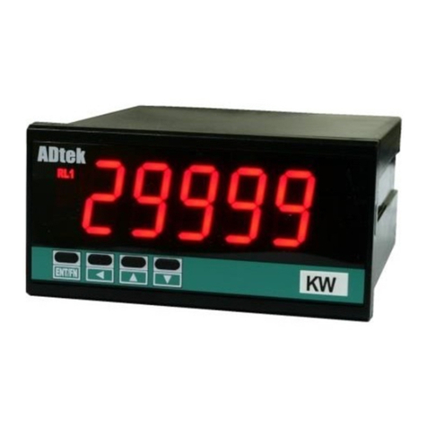
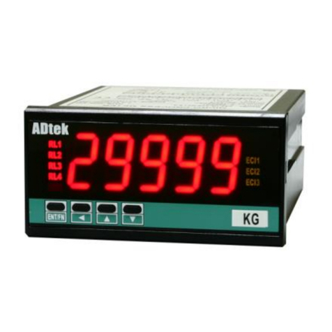
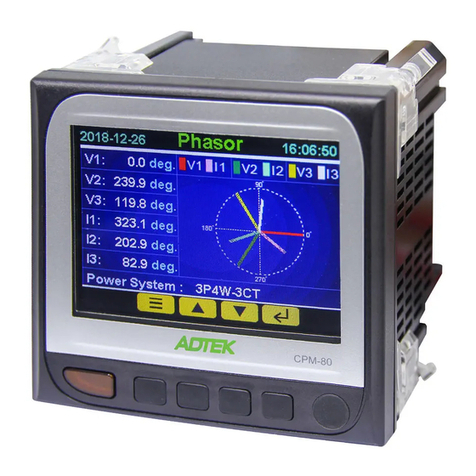
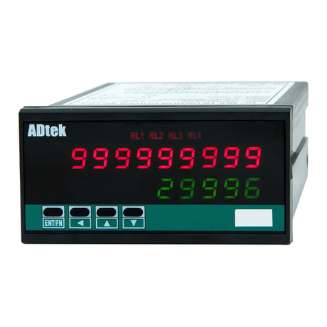
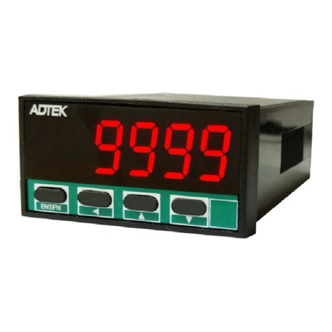
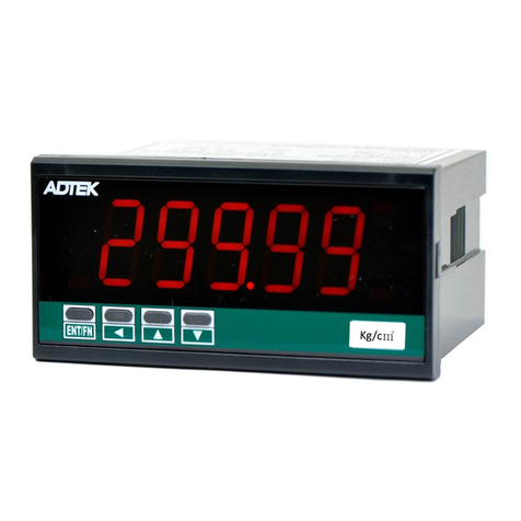
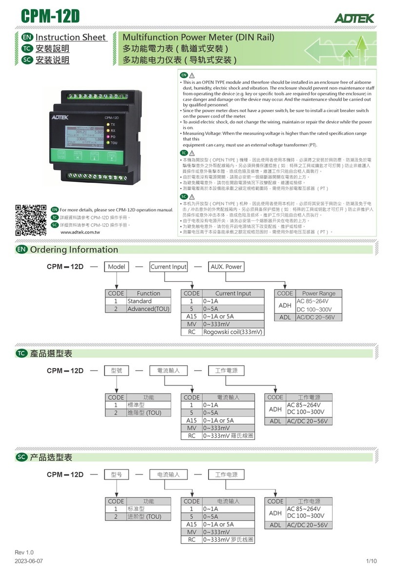
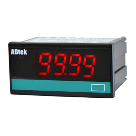
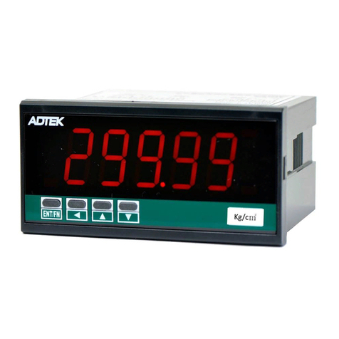
ADTEK CS2-MC User manual

1 / 19 CS2-MC Manual 2014/9/9
CS2-MC Multifunction A/B Phase Counter Manual
■ FEATURE
●Measuring Pulse 0.01Hz~6KHz(A/B phase: 3KHz for each channel);
Contact / NPN / PNP / Voltage Pulse can be switch on rear of meter
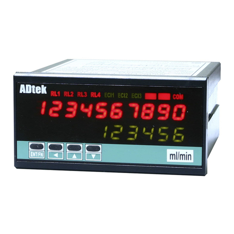
●2 rows LED,display Totalizer 、Batch、Batch count
●CS2-MC Multifunction Counter design for pulse signal input,
sensors: Proximity switch, Photoelectric sensor, Encoder.... etc.,
●Counter (Increment / Decrement), location-based, batch and
other displays, control, with remote communication capabilities.
●4 relays, each can be individual programmed for N/R/C/E/do mode and
timer function.
●3 external control input for Reset, Gat of totalizer and/or batch
●Analogue Output and RS485(Modbus RTU mode) available in option
FUNCTIONS
■Counting
Counting mode :
AB-PHASE:
Up/Down Individual(Individual counting model)
Up/Down Command(Command model)
Up Mode
Down Mode

2 / 19 CS2-MC Manual 2014/9/9
SCALE Default: Ai.Lo: 0%, Ai.Hi: 100%; Lo.SC: 0.00, Hi.SC: 100.00
Change to Ai.Lo: 0%, Ai.Hi: 75%; Lo.SC: 0.00, Hi.SC: 199.99
0.00
199.99
100.00
0.00% 100.00%50.00%
INPUT 75.00% 0.00% 100.00%50.00%
OUTPUT
199.99
100.00
0.00
Setted Scaling: Lo.SC: 0.00, Hi.SC: 199.99;
Desired Output: Ao.Lo: 50.00
(
PV
)
, Ao.Hi: 150.00
(
PV
)
50.00
150.00
SCALE
■ DISPLAY FUNCTIONS
Enter the confirm time: This function is mainly to avoid
the scene of the disturbance caused
by the malfunction surge; Please note,
thistime setting is every 16
milliseconds (16msecond) for
Units,
please refer to the following example
[debnc] set to be 5, it means
5 x 16 msecond = 80 msecond
That, contact input must be greater
than 60msecond, the instrument
Will identify the correct input,
otherwise ignore this input.。
Select the Up display
Can be set Totalizer or Batch Count display。
Counter Set Factor
Display value=pulse x multiplier (cnTsf)
Shows the multiplier can be set to the range
of 0.100000 - 9.99999with a different decimal point
position
Offset:
Counter reset after the [inPUt GroUP]] in [oFSEt set
the startingvalue (for example: 200),Will be starting
from the default value (200) number of the
startingproduct.
■ RELAY FUNCTIONS ■Analogue output
This table provides
f
our relay output options, you can
choose the corresponding control volume and mass
execution N / R / C / E four control output
Ao.LS:Analogue Output relative Low Scale
Ao.HS:Analogue Output relative High Scale
Fine Zero & Span Adjustment for Analog Output:
Users can get Fine Adjustment of analogue output
by front key of the meter. Please connect standard
meter to the terminal of analogue output. To press
the front key(up or down key) of meter to adjust
and check the output.
High Limited for Analog Output :
0.00% 100.00%50.00%
OUTPUT
199.99
100.00
0.00
Setted Scaling: Lo.SC: 0.00, Hi.SC: 199.99;
Desired Output:
A
o.Lo: 50.00
(
PV
)
, Ao.Hi: 150.00
(
PV
)
; Ao.LMt: 80.00%
50.00
150.00
SCALE
A
o.LMt: 80.00%(=130.00)
■External Control Inputs (ECI)
Input mode: 2 ECI points, Contact Implementation
can be set individually and the total volume-related
functions
Power or batch power reset:
Total suspended and / or batch several the plot
reset of the total and / or batch to "0"
Suspended total / batch Reset of the total / batch
to ta l
ba tch
By E.C.I. Pause
O
N
Level Trigger ON ON ON By E.C.I. Pause
orfrontkey
O
N
EdgeTrigger ON ON
to tal
batch
N MODE:
When the condition of Set Point is met.
1. the relay will be energized;
2. The totalizer will run as same as
usual; until manual reset by front key
or by rear terminal, the totalizer will
be reseted to“0” and the relay willbe
de-energized.
Set
Point
Relay
Output ON
Totalizer
Manual
Reset
R MODE:
When the condition of Set Point is met:
1. The relay will be energized; until the
time is over Relay outputtime (rY.1(or 2).ot).
2. The totalizer will run as same as usual; until the
time is over Relay output time (rY.1(or 2).ot),The
totalizer will be reseted to “0
ON
Auto
Reset
Relay output Time
Totalizer
Set
Point
Relay
Output
C MODE:
When the condition of Set Point is met:
1. The relay will be energized; until the
time is over Relay output time (rY.1(or 2).ot).
2. The totalizer will be reseted to “0”,
then counts-up from “0”.
ON
Relay
Output
Set
Point
Auto
Reset Totalizer
Relay output Time
Set
Point
Relay
Output ON
Manual
Reset
Relay output Time
Totalizer
E MODE:
When the count reaches the set value:
1. relay output, until rYot (Relay outputtime) to
set time has elapsed,the relay will revert to
the (de-energized)
2. count the number will continue to plot, until the
button manual reset by the panel
reverted by the ECI terminal short
circuitCount value from "0" to re-plot several

3 / 19 CS2-MC Manual 2014/9/9
■RS485 communication ■INSTALLATION
Protocol: ModBus RTU Mode
Baud Rate: 1200/2400/4800/ 9600/19200 bps
Data Bits: 8 bit
Stop Bits: 1bit or 2 bit
Parity: Even / Odd / None
Divice Number: 1~255
1.0~8.0 mm
FIX HOL DER:
104 mm(L) / W M3
PANEL CUT-OUT:
92+0. 2(W) x 44+0.2 (H ) m m
ENT
/
F
?
?
m
RL
1
RL
RL
RL
CO
CI
CI
Application ■CONNECTION DIAGRAM
D-S
A
B
1 2 3 4 5 6 7 8 9 10
NPN ON ON
PNP ON ON
M.C. ON ON ON ON
5
V
P
12VPON ON
24VPON ON
D-S on down side is ON
29
Rela
y
3
b c a
Rela
y
2
b c a
Rela
y
1
a c
Rela
y
4
ac
Analogue
output
A B
RS485
port
ECI1 ECI3 COMECI2
E.C.I
45 6 7 8 9 10
11 12 1413
Terminal block:
10A/300Vac,
M2.6, 1.3~3.3mm2
(16~12AWG)
AC85~265V
DC 100~300V
AUX.Power
ADH
D-S A D-S B
1 5 6 10
FG
Si
g
nal in
p
ut
Count
/
Pulse
A +IN
B +IN
+12Vd
COM
21 22 23 24 25 26 27 28 30 31 32 33 34
10 Pin DIP SWITCH
Connected to 11 (A + IN), 12 (B + IN) pin signal level required toclear the high and
low potential,Do not floating (high impedance).
Please check the voltage of power supplied first, and then connect to the
specified terminals. It is recommended that power supplied to the meter be
protected by a fuse or circuit breaker
Power Supply
A
C 85~265
V
DC 1 00~300V
Filter or Transf orme r
L
N
G
L
N
G
1A
FUSE
9108
Sensor input connection
D-S
A
B
1 2 3 4 5 6 7 8 9 10
NPN ON ON
PNP ON ON
M.C. ON ON ON ON
5
V
P
12VPON O N
24VPON ON
D-S on down side is ON
Please change the dip
-
switchonrearof meterto
match inputthe mode andlevel
11 12 1413
A +IN
+12Vdc
B +IN
+Vdc
A
Out
BOut
COM
0V
RS 485 Communic ation Port Analogretransmitoutput
Max.Distance: 1200M
Ter mina t e Re s isto r
(at latest unit):
12 0 ~3 0 0oh m/ 0. 25 W
( ty p ic al : 15 0oh m )
A
B
29 323130 34333
2
31
With the proximity switches, photoelectric
switches, encoders ...etc., do the count (plus / less
count), length, location, location,batch etc.
displays, control, and remote communication
capabilities.
RS 485 Modbus RTU Mode (up to 38400bps)
Analo
g
Output 0~10V/0(4)~20mA
AL AL
Flowmete
r
ENT/F
N
▼
PLS CO
M
ECI1 ECI2 mwh kwhMK kw W
◄
WH
▲
ENT/F
N
▼
PLS CO
M
ECI1 ECI2 mwh kwhMK kw W
◄
WH
▲
■FRONT PANEL
ENT/FN m
RL
1
RL
2
RL3 RL
4
COMCI11 CI2 CI3
Relay status
Indication
Operation Ke
y
Up screen
for Totalizer
Comm. status
Control Input
status
Engineer Unit
Down screen
for PV or Batch
/
BR
/
TR
B
R
batch zero butto TRTotal zero button
DIMENSIONS
92.0+0.2
44.0+0.2
PANEL CUT-OUT
96.0
48.0
FRONT VIEW
Unit: mm
8.0 12.0
100.0
Dimensions: 96mm x 48mm x 120mm
Panel Cutout: 93mm x 45mm (advise)

4 / 19 CS2-MC Manual 2014/9/9
■ OPERATIONS:
Error Massage DISPLAY REMARK
EFORE POWER ON, PLEASE CHECK THE SPECIFICATION
AND CONNECTION AGAIN
SELF-DIAGNOSIS AND ERROR CODE:
/ :EEPROM occurs error (Please send back to
manufactory for repaired)
/ :Didn’t execute the calibrate of output
Signal (Please process Calibrating
Output Signal)
/ :Output Signal calibrated error (Please check Calibrating
Output Signal)
■ Operating Key:
*Please access to the Programming Level to check and set the parameters when users start to run the meter
Operating Key: 4 keys for
Enter(Function) /
Shift(Escape) /
Up key /
Down key
The meter has designed operation similar as PC's and Enter . In any page, press
key means "enter" or
"confirm setting", and press
key means "escape( Esc )" or "shift".
In Programming Level, the screen will return to Measuring Page after do not press any key over 2 minutes, or press
for 1 second.
Function Index Setting Status
(= )
Enter/Fun key
(1) In any page, press
to access the level or
function index
(2) From the function index to access setting status
(3) Setting Confirmed, save to EEProm and go
to next function index
(=
)
Shift key
(1) In measuring page, press
for 1 second to
access user level.
(2) In function index, press
for 1 second to go
back upper level.
(3) In function group index, press
for 1 second
to go back measuring page
(4) In setting status, press
to Shift the
setting position.
(5) In setting status, press
for 1 second to
abort setting and go back this function
index.
(=
)
Up key
(1) In function index, press
to go back to
previous function index
(2) In setting status for function, press
to
select function
(3) During number Setting, press
can roll
the digit up
(= )
Down key
(1) In Function Index Page, press
will go to the
next Function Index Page.
(2) In setting status for function, press
to
select function
(3) During number Setting, press
can roll
the digit down.
■ FRONT PANEL
ENT/FN m
RL
1
RL
2
RL3 RL
4
COMCI11 CI2 CI3
Relay status
Indication
Operation Ke
y
Up screen
for Totalizer
Comm. status
Control Input
status
Engineer Unit
Down screen
for PV or Batch
/
BR
/
TR
B
R
batch zero butto TRTotal zero button
LED:
: 10 digital present values:
0.28”(7.2mmH) red LED
:6 digital present values: 0.28”(7.2mmH)green
LED
RL1 RL2 RL3 RL4 Relay Energized: 4 square red LED
RL1 display when Relay 1 has been energized;
RL2 display when Relay 1 has been energized;
RL3
display when Relay 1 has been energized;
RL4 display when Relay 1 has been energized;
COM RS 485 Communication: 1 square orange LED;
will flash express the meter is receive or send data,
and flash quickly means the data transient quicker.
EC1 EC2 EC3 E.C.I.:3 square green LED;
EC1 display when E.C.I. 1 has been closed(dry
contact);
EC2 display when E.C.I. 1 has been closed(dry
contact);
EC3 display when E.C.I. 1 has been closed(dry
contact);

5 / 19 CS2-MC Manual 2014/9/9
Pass Code: Settable range:0000~9999;
User must key-in the exactly pass code
for access to [Programming Level].
Otherwise, the meter will return to
measuring page. If user forgets the
pass code, please contact with your
service window
Function Lock: There are 4 levels programmable:
User Level / Engineer Level / All(User
Level & Engineer Level) / None;All
lock. User can access to all level for
checking but can not setting.
Front Key Function
The
Key can be set to be the same function as the
setting of [ ecI1](ECI).
Ex. The [ ecI1]set to be pVhld and the function [E1=up]
set to be y e s in [ eci group]. When user presses
Key, the PV will hold as like as terminals of ECI1 close.
■ OPERATING FLOW CHART: Plesae refer to operating manual for detail description
Power ON
Self-diagnosis
0−1
ry!sp: Relay 1
Set-point
0−4
ry$sp: Relay 4
Set-point
Display the
model
0−2
ry@sp: Relay 2
Set-point
0−5
model of the
meter firmware
version
Checking only
Checking only
Relay Set-point
Total:
-1999999999~+9999999999
Batch: -199999~+999999
Show
the firmware
version
0−3
ry#sp: Relay 3
Set-point
MEASURING PAGE
Press 1sec Access
Escape Press 1sec
Enter the password to access
Programming Level
Y
ES
P.code
NO
Default:1000
INPUT
GROUP
RELAY
GROUP
EXTERNAL
CONTROL
INPUT (E.C.I)
GROUP
ANALOGUE
OUTPUT
GROUP
A−1
In.Typ: Input
Type
Ab.P-1
Ab.P-2
Ab.P-4 idV
Cmd UP
down
B−1
rY1.Md: Relay
1 energized
mode
oFF btCH.n
btCH.r
btCH.C
btCH.E totL.n
totL.r totL.C
C−1
ECi.1:
External
Control
Input 1
nonE GAtE
rESEt tL.GtE
tL.rSt bt.GtE
bt.rSt
D−1
Ao.SEL:
Output
corresponds
batch / Batch
Counter/ total
selection
bAtCH
bt.Cnt
totAL
NEXT
NEXT
NEXT
NEXT
User Level
Press for 1 sec. to back Measuring Page
Programming Level
Press for 1 sec. to back Measuring

6 / 19 CS2-MC Manual 2014/9/9
A−2
trG.Md:
Trigger Mode
AU-bU
AU-bd
Ad-BU
Ad-Bd
B−2
rY1.ot: Relay 1
energizing
time
0.00.0~
9(M).59.9(S)
C−2
ECi.2: External
Control
Input 2
nonE GAtE
rESEt tL.GtE
tL.rSt bt.GtE
bt.rSt
D−2
Ao.Typ:
Analogue
Output type
and range
selection
v.0-10 v. 0-5
v.1-5 A.0-20
A.4-20
A
.0-10
A−3
PPr:
Pulse/Rotation
1~9999
B−3
rY2.Md: Relay
2 energized
mode
oFF btCH.n
btCH.r btCH.C
btCH.E totL.n
totL.r totL.C
totL.E do
C−3
ECi.3: External
Control
Input 3
nonE GAtE
rESEt tL.GtE
tL.rSt bt.GtE
bt.rSt
D−3
Ao.LS:
Analogue
Output
relative Low
Scale
Batch
Counter/ total
-1999999999~
9999999999
batch
-199999~
999999
A−4
Cnt.SF:
Multiplier
0.100000~
9.99999
B−4
rY2.ot: Relay 2
energizing
time
0.00.0~
9(M).59.9(S)
C−4
dEbnc:
Debouching of
external
control Input
5~250(x16ms)
D−4
Ao.HS:
Analogue
Output
relative High
Scale
Batch
Counter/ total
-1999999999~
9999999999
batch
-199999~
999999
A−5
dP: Decimal
Point of total
& batch
0/0.0/0.00/
0.000/0.0000/
0.00000
B−5
rY3. Relay 3
energized
mode
oFF btCH.n
btCH.r btCH.C
btCH.E totL.n
totL.r totL.C
totL.E do
D−5
Ao.Zro:
FineZero
Adjustment for
Analog Output
-32768~32767
A−6
ttL.Md: display
mode (total /
batch) Select
noMAL
bt.Cnt
B−6
rY3.ot: Relay 3
energizing
time
0.00.0~
9(M).59.9(S)
D−6
Ao.SPn:
Fine Span
Adjustment
for Analog
Output
-32768~32767
A−7
oFSEt:
The default
start point
setting
0~999999
B−7
rY4.Md: Relay
4 energized
mode
oFF btCH.n
btCH.r btCH.C
btCH.E totL.n
totL.r totL.C
totL.E do
D−7
Z.S.CLr: Clear
Fine Zero /
Span
Adjustment
for Analog
Output
nonE Ao.Zro
Ao.SPn ALL
A−8
P.CodE: Pass
Code setting
for access to
Programming
Level
0000~9999
B−8
rY4.ot: Relay 4
energizing
time
0.00.0~
9(M).59.9(S)
D−8
Ao.LMt:
Analog Output
High Limit
0.00~110.00%
A−9
Function
Level Lock
nonE USEr
EnG ALL
ENT
RS485
GROUP
E−1
Adres: Device
number of the
meter
1~255
When the relay operation mode change
relay points will reset to zeroPlease
re-setting the relay point

7 / 19 CS2-MC Manual 2014/9/9
E−2
baud: Baud
rate
1200 2400
4800 9600
19200
E−3
PritY: Parity
n.Stb.1
n.Stb.2 odd
EvEn
■ OPERATING STEPS
USER LEVEL
Default DESCRIPTION PARAMETERS Note
POWER
ON
Please check the specification and wiring
first.
Self-diagnosis (LED All bright)
Totalizer
Totalizer
Batch
model number
firmware version
Measuring Page (10 digital
Totalizer +6 digital Batch)
Press for 1 second can
back to Measuring Page
0−1
rY1.SP:Relay 1 Set-point setting
Please check the setting of
Relay energized mode and keep
in mind.
If the relay mode set to relative
immediate value, the energized
mode will be Hi or Lo.
Setting Range:
Immediate Value (PV):
-199999~999999
Totalizer:
-1999999999~9999999999
Shift Up Down
0−2
rY2.SP: Relay 2 Set-point
setting
Setting Range:
Immediate Value (PV):
-199999~999999
Totalizer:
-1999999999~9999999999
Shift Up Down
0−3
rY3.SP: Relay 3 Set-point
setting
Setting Range:
Immediate Value (PV):
-199999~999999
Totalizer:
-1999999999~9999999999
Shift Up Down

8 / 19 CS2-MC Manual 2014/9/9
0−4
rY4.SP: Relay 4 Set-point
setting
Setting Range:
Immediate Value (PV):
-199999~999999
Totalizer:
-1999999999~9999999999
Shift Up Down
0−5
Frimware version
Model number
Review only
It will be announce in our
website when it has been
version chan
g
ed.
0−1
Cyclic to first page
Press
for 1 second can back to Measuring Page in any
page
PROGRAMMING LEVEL
Default DESCRIPTION PARAMETERS Note
MEASURING PAGE
PASS CODE PAGE If user wants to change the pass
code, please go to step A-8 to set.
Please remind the new pass code.
Y
ES
密碼正確
NO
Enter the pass code to get into
programming level
INPUT
GROUP
RELAY
GROUP
EXTERNAL
CONTROL
INPUT
GROUP
ANALOGUE
OUTPUT
GROUP
RS485
GROUP
PRESS
TO ENTER
PRESS
TO ENTER
PRESS
TO ENTER
PRESS
TO ENTER
PRESS
TO ENTER
Press for 1 second to back Measuring
P
畫面

9 / 19 CS2-MC Manual 2014/9/9
INPUT GROUP
Default DESCRIPTION PARAMETERS Note
INPUT GROUP INDEX In following page, press
for 1 second to back INPUT
GROUP INDEX.
A−1
In.Typ:Input Type
Setting Range:
Ab.P-1 Ab.P-2
Ab.P-4 idV
Cmd UP down
Ab.P-1 (A/B Phase1):
A/B Phase 1,Input pulse
per cycle count 1, can be
resolved to a cycle
Ab.P-2 (A/B Phase2):
A/B Phase 2,Every 1/2
cycle of the input pulse count
one, can be resolved to a 1/2
cycle
Ab.P-4 (A/B Phase4):
A/B Phase 4,Every 1/4
cycle of the input pulse count
one, can be resolved to a 1/4
cycle
idV (Individual I/P):
Individual counting mode,
input A is Up ,input B is
Down
Cmd (Command I/P):
Command mode,Input A is
Up,Input B is Control signal,
control input A whether to
change Down
UP (Up Count):
input A is Up,Input B is
Control signal,control input
A Whether to suspend count。
down (Down Count):
input A is Down,Input B is
Control signal,control input
A Whether to suspend coun
&Up&Down Enter
A−2
trG.Md: Trigger Mode
AU-BU: A positive-edge,B
positive-edge trigger
AU-Bd: A positive-edge,B
negative-edge trigger
Ad-BU: A negative-edge,B
positive-edge trigger
Ad-Bd: A negative-edge,B
ne
g
ative-ed
g
e tri
gg
e
r
Setting Range:
AU-bU / AU-bd / Ad-BU /
Ad-Bd
&Up&Down Enter

10 / 19 CS2-MC Manual 2014/9/9
A−3
PPr:Pulse Per Rotation
The input pulse number must be
divided by this value, the count
before doing arithmetic
Setting Range: 1~9999
Shift Up Down
A−4
Cnt.SF:Counter Set Factor
After the count value is multiplied
by this value is the display value
Setting Range:
0.10000~9.99999
Shift Up Down
A−5
dP(Decimal Point):
Decimal Point of Totalizer & Batch
Setting Range:
0 / 0.0 / 0.00 / 0.000 / 0.0000
/ 0.00000
&Up&Down Enter
A−6
ttL.Md:Totalizer Mode of up
screen
Up screen display selection
(Totalizer & Batch)
Setting Range:
noMAL(Normal): Totalizer
bt.Cnt(Batch Count): Batch
&Up&Down Enter
A−7
oFSEt(Offset): default start point
setting
Setting Range:0~999999
Shift Up Down
A−8
P.CodE(Pass Code): Please
remind and write down the new
pass code so that get into
programming level.
Setting Range:: 0000~9999
Shift Up Down
A−9
F.LoCk(Function Lock): There
are 4 levels selectable for lock.
Setting Range:
nonE(None):no lock all
USEr(User Level): User level
lock. User can get into
user level for checking
but setting.
EnG(Engineer Level):
Programming level lock.
User can get into
programming level for
checking but setting
ALL(All Level):User can get
into all level for checking
but setting
&Up&Down Enter

11 / 19 CS2-MC Manual 2014/9/9
RELAY GRUOP
Default DESCRIPTION PARAMETERS Note
RELAY GROUP INDEX In following page, press
for 1 second to back RELAY
GROUP INDEX.
B−1
rY1.Md:Relay 1 energized mode
Setting Range:
oFF(Turn off the Relay):Turn
off the Relay and relative
LED
btcH.n: Batch control with N
mode energized
btCH.r:Batch control with R
mode energized
btCH.C:Batch control with C
mode energized
btCH.E:Batch control with E
mode energized)
totL.n:Totalizer control with
N mode energized)
totL.r:Totalizer control with
R mode energized):
totL.C:Totalizer control with
C mode energized
totL.E:Totalizer control with
E mode energized
do(Digital Output):When has
the RS485 function, the
function of the relay can be
used as DO, under
instruction from the RS485
mandatory relay。
&Up&Down Enter
N
M
ODE
:
When the conditionof SetPointismet.
1. the relaywill be energized;
2. The totalize r will run as same as
usual;until manual reset byfront key
or by rear terminal,thetotalizer will
be reseted to “0”and the relaywill be
de-energized.
Set
Point
Relay
Ou t
p
ut
O
N
Totalizer
Manual
Res et
RMODE:
When the condition of Set Point is met:
1. The relay will beenergized; until the
tim e is over Rel ay ou tp ut ti me (rY.1(or 2).ot).
2. The totalizer will run as same as usual; untilthe
time is over Relay output time (rY.1(or 2).ot),The
totalizerwill be reseted to “0
ON
Auto
Reset
Relay output Time
T
otalize
r
S
e
t
Point
Relay
Ou tp ut
C MODE:
When the conditionof SetPointismet:
1. The relay will be energized; until the
time is over Relay output time (rY.1(or 2).o t).
2. The totalizerwill be reseted to “0”,
then counts-up from“0”.
ON
Relay
Ou tp ut
Set
Point
Au to
Res et Totalizer
Relayoutput Ti me
Set
Point
Relay
Ou t
p
ut
O
N
Manual
Reset
Re la y o utput Ti me
T
otalize
r
E
MODE
:
When the countreaches the set value:
1. relay output, until r Yot (Rela y ou tpu t ti me) to
set time has elapsed,the relay will revert to
the (de-energized)
2. count the numberwill continueto plot,until the
button manual reset by the panel
reverted bythe ECI terminal short
circuitCount value from "0" tore-plot several
B−2
rY1.ot:Relay 1 energized time
(N mode is no such function)
Setting Range:
0:00.0~9m:59.9s
Shift Up Down
B−3
rY2.Md:Relay 2 energized mode ….as Relay 1 Energized
Mode…
Setting Range:
oFF / btcH.n / btCH.r /
btCH.C / btCH.E / totL.n /
totL.r / totL.C / totL.E / do

12 / 19 CS2-MC Manual 2014/9/9
B−4
rY2.ot:Relay 2 energized time
(N mode is no such function)
Setting Range:
0:00.0~9m:59.9s
Shift Up Down
B−5
rY3.Md:Relay 3 energized mode ….as Relay 1 Energized
Mode
oFF / btcH.n / btCH.r /
btCH.C / btCH.E / totL.n /
totL.r / totL.C / totL.E / do
B−6
rY3.ot:Relay 3 energized time)
(N mode is no such function)
Setting Range:
0:00.0~9m:59.9s
Shift Up Down
B−7
rY4.Md:Relay 4 energized mode ….as Relay 1 Energized
Mode
oFF / btcH.n / btCH.r /
btCH.C / btCH.E / totL.n /
totL.r / totL.C / totL.E / do
B−8
rY3.ot:Relay 3 energized time):
(N mode is no such function)
Setting Range:
0:00.0~9m:59.9s
Shift Up Down
EXTERNAL CONTROL INPUT(E.C.I.) GRUOP
Default DESCRIPTION PARAMETERS Note
EXTERNAL CONTROL INPUT
GROUP INDEX
In following page, press
for 1 second to back
EXTERNAL CONTROL
INPUT GROUP INDEX.
C−1
ECi.1: External Control Input 1 Setting Range:nonE GAtE
rESEt tL.GtE
tL.rSt bt.GtE
bt.rSt
nonE(None): No function
GAtE(Gate): This feature is
batch & total suspended
rESEt:Reset for Totalizer &
Batch
tL.GtE(Gate for Totalizer):
This feature is total
suspended
tL.rSt:Reset for Totalizer
bt.GtE(Gate for Batch): This
feature is batch
suspended
bt.rSt:Reset for Batch
&Up&Down Enter
C−2
ECi.2:External Control Input 2 same as ECI1
…other as same as ECI1…
nonE / GAtE / rESEt / tL.GtE
/ tL.rSt / bt.GtE / bt.rSt
&Up&Down Enter

13 / 19 CS2-MC Manual 2014/9/9
C−3
ECi.3:External Control Input 3 same as ECI1
…other as same as ECI1…
nonE / GAtE / rESEt / tL.GtE
/ tL.rSt / bt.GtE / bt.rSt
&Up&Down Enter
C−4
dEbnc:Debouncing of external
control Input
Setting Range:
5~250( x 16ms)
Shift Up Down
ANALOGUE OUTPUT GRUOP
Default DESCRIPTION PARAMETERS Note
ANALOGUE OUTPUT GROUP
INDEX
In following page, press
for 1 second to back
ANALOGUE OUTPUT
GROUP INDEX.
D−1
Ao.SEL:Analogue output
relative parameter
Totalizer/Batch/PV selection
Setting Range:
bAtCH:Batch
bt.Cnt:Batch Count
totAL:Totalizer
&Up&Down Enter
D−2
Ao.tYP:Analogue Output type Setting Range:
v.0-10(0~10V) /
v. 0-5(0~5V) / v.1-5(1~5V) /
A.0-20(0~20mA) / A.4-20(4~20mA)
/ A.0-10(0~10mA)
&Up&Down Enter
D−3
Ao.LS:Analogue Output relative
Low Scale
Setting Range:
Totalizer / Batch Count:
-1999999999~9999999999
Batch: -199999~999999
Shift Up Down
※Ex:Ao.TYP set 4~20mA,Display
Range 0~1000.0;if Ao.LSsetting
200.0,Display 200.0 is output 4mA
D−4
Ao.HS:Analogue Output relative
High Scale
Setting Range:
Totalizer / Batch Count:
-1999999999~9999999999
Batch: -199999~999999
Shift Up Down
※Ex:Ao.TYP set 4~20mA,Display
Range 0~1000.0;if Ao.HSsetting
800.0,Display 800.0 is output
20mA
NEXT

14 / 19 CS2-MC Manual 2014/9/9
D−5
Ao.Zro(Fine Zero Adjustment for
Analog Output): Users can get
Fine Adjustment of analogue output
by front key of the meter. Please
connect standard meter to the
terminal of analogue output. To
press the front key(up or down key)
of meter to adjust and check the
meter the output。
Setting Range: -32768~32767
Shift Up Down
D−6
Ao.SPn(Fine Span Adjustment for
Analog Output)
Setting Range: -32768~32767
Shift Up Down
D−7
Z.S.CLr:Clear Fine Zero / Span
Adjustment for Analog Output
Setting Range:
nonE: Do not clear
Ao.Zro: Clear low adjustment
Ao.SPn: Clear high adjustment
both: Clear low and high
adjustment
&Up&Down Enter
D−8
Ao.LMt:Analog Output High
Limit
0.00% 100.00%50.00%
OUTPUT
199.99
100.00
0.00
Setted Scaling: Lo.SC: 0.00, Hi.SC: 199.99;
Desired Output: Ao.Lo: 50.00(PV), Ao.Hi: 150.00(PV); Ao.LMt: 80.00%
50.00
150.00
SCALE
Ao.LMt: 80.00%(=130.00)
Setting Range: 0.00~110.00%
of FS
Shift Up Down
RS485 GRUOP
Default DESCRIPTION PARAMETERS Note
ENT
RS485 GROUP INDEX In following page, press
for 1 second to back RS485
GROUP INDEX.
E−1
Adress:Device number of the
meter
Setting Range: 1~255
Shift Up Down
E−2
bAUd:Baud rate Setting Range: 1200 / 2400 /
4800 / 9600 / 19200
&Up&Down Ente
E−3
PritY:Parity Setting Range:
n.Stb.1: None, 1 stop bit
n.Stb.2: None, 2 stop bits
odd: odd
EvEn: Even
&Up&Down Ente

15 / 19 CS2-MC Manual 2014/9/9
RS485(ModBus RTU Mode)
■ Modbus RTU Mode
一、 Function 03H (Read Holding Registers)
Request Data Frame EX: Read the data of display value(0000H starts from 1 Word)
SLAVE
Address
FUNCTION
Starting
Address Hi
Starting
Address Lo
No. of Word
Hi
No. of Word
Lo
CRC
Lo
CRC
Hi
01H 03H 00H 00H 00H 01H 84H 0AH
Response Data Frame; EX: The response value is ”0”
SLAVE
Address
FUNCTION Byte
count
Data
Hi
Data
Lo
CRC
Lo
CRC
Hi
01H 03H 02H 00H 00H B8H 44H
Request Data Frame (EX: Continue to request the data of 10 points)
SLAVE
Address
FUNCTION
Starting
Address Hi
Starting
Address Lo
No. of Word
Hi
No. of Word
Lo
CRC
Lo
CRC
Hi
01H 03H 00H 00H 00H 0AH C5H CDH
Response Data Frame
SLAVE
Address
FUNCTION Byte
count
Data(1)
Hi
Data(1)
Lo
… … Data(10)
Hi
Data(10)
Lo
CRC
Lo
CRC
Hi
01H 03H 14H 00H 00H … … 01H 00H -- --
二、 Writing Command by Function 06H (Preset Single Register)
Request Data Frame
SLAVE
Address
FUNCTION
Code
Starting
Address Hi
Starting
Address Lo
Preset
DATA Hi
Preset
DATA Lo
CRC
Lo
CRC
Hi
01H 06H 00H 00H 00H 02H 08H 0BH
Response Data Frame
SLAVE
Address
FUNCTION
Code
Starting
Address Hi
Starting
Address Lo
Preset
DATA Hi
Preset
DATA Lo
CRC
Lo
CRC
Hi
01H 06H 00H 00H 00H 02H 08H 0BH
■ CS2-MC ADDRESS TABLE **Address number are Hexadecimal
User Level
Name Address Range Explain Initial Write/Read Note
Three Word Area
0000h -1999999999~
9999999999 Totalizer (High Word) 0 R
0001h Totalizer (Mid Word) R
0002h Totalizer (Low Word) R
0003h 0000000000~
9999999999 Batch Count (High Word) 0 R
0004h Batch Count (Mid Word) R
0005h Batch Count (Low Word) R
0006h -1999999999~
9999999999 Relay1 Set Point (High Word) 3000 R/W
0007h Relay1 Set Point (Mid Word) R/W
0008h Relay1 Set Point (Low Word) R/W
0009h -1999999999~
9999999999 Relay2 Set Point (High Word) 6000 R/W
000Ah Relay2 Set Point (Mid Word) R/W
000Bh Relay2 Set Point (Low Word) R/W
000Ch -1999999999~
9999999999 Relay3 Set Point (High Word) 9000 R/W
000Dh Relay3 Set Point (Mid Word) R/W
000Eh Relay3 Set Point (Low Word) R/W
000Fh -1999999999~
9999999999 Relay4 Set Point (High Word) 12000 R/W
0010h Relay4 Set Point (Mid Word) R/W
0011h Relay4 Set Point (Low Word) R/W

16 / 19 CS2-MC Manual 2014/9/9
Name Address Range Explain Initial Write/Read Note
0012h -1999999999~
9999999999
Analogue Output Low Scale (High Word) 0 R/W
0013h Analogue Output Low Scale (Mid Word) R/W
0014h Analogue Output Low Scale (Low Word) R/W
0015h -1999999999~
9999999999
Analogue Output High Scale (High Word) 12000 R/W
0016h Analogue Output High Scale (Mid Word) R/W
0017h Analogue Output High Scale (Low Word) R/W
Reserved 0018h
Reserved 0019h
Reserved 001Ah
Reserved 001Bh
Reserved 001Ch
Reserved 001Dh
Two Word Area
001Eh -199999~999999
Batch (High Word) 0 R
001Fh Batch (Low Word) R
0020h 0.10000~9.99999
Counter Set Factor (High Word) 1.00000 R/W
0021h Counter Set Factor (Low Word) R/W
0022h 0~999999
Offset (High Word) 0 R/W
0023h Offset (Low Word) R/W
One Word Area
Reserved 0024h
Reserved 0025h
Reserved 0026h
Reserved 0027h
Reserved 0028h
Reserved 0029h
RELAY
STATUS
002Ah 0~1 RELAY STATUS
bit0~bit3: relay1~relay4;
0=Relay off 1=Relay on
00h R/W
E.C.I.
STATUS
002Bh 0~1 External Control Input STATUS
bit0~bit2: E.C.I.1~ E.C.I.3;
0=Un-triged 1=Triged
00h R
SYSTEM
STATUS
002Ch SYSTEM STATUS
bit0=1, Input EEP fail;
bit1=1, N/A;
bit2=1, N/A;
bit3=1, Analogue Output calibration fail;
bit4=1, Analogue Output calibration NG
00h R
002Dh 1~9999
Pulse Per Rotation 1 R/W
Reserved 002Eh
Reserved 002Fh

17 / 19 CS2-MC Manual 2014/9/9
Engineer Level
【Input Group】
Name Address Range Explain Initial Write/Read Note
0030h 0~6 Input Type
0: A/B Phase1 1: A/B Phase2
2: A/B Phase4 3: Individual I/P
4: Command I/P 5: Up Count
6: Down Count
0 R/W
0031h 0~3 Trigggger Mode
0: AU-BU 1: AU-BD 2: AD-BU 3: AD-BD
0 R/W
0032h 0~5
Decimal Point
0: 0 1: 0.0 2: 0.00 3: 0.000 4: 0.0000
5: 0.00000
0 R/W
0033h 0~1 Totalizer Mode of up screen
0:Normal 1:Batch Count
0 R/W
0034h 0000~9999
Pass Code 1000 R/W
0035h 0~3 Function Lock
0: none 1: User Level 2: Engineer Level
3: All
0 R/W
【Relay Group】
Name Address Range Explain Initial Write/Read Note
003Ah 0~9 Relay 1 Energized Mode
0: oFF(no use);
1: btCH.n(Batch with N Mode)
2: btCH.r(Batch with R Mode)
3: btCH.C(Batch with C Mode)
4: btCH.E(Batch with E Mode)
5: totL.n(Totalizer with N Mode)
6: totL.r(Totalizer with R Mode)
7: totL.C(Totalizer with C Mode)
8: totL.E(Totalizer with E Mode)
9: Do(Digital Output)
1 R/W
003Bh 0000~5999
(0.1second)
Relay 1 Energized Time
10 R/W
003Ch 0~9 Relay 2 Energized Mode
0: oFF(no use);
1: btCH.n(Batch with N Mode)
2: btCH.r(Batch with R Mode)
3: btCH.C(Batch with C Mode)
4: btCH.E(Batch with E Mode)
5: totL.n(Totalizer with N Mode)
6: totL.r(Totalizer with R Mode)
7: totL.C(Totalizer with C Mode)
8: totL.E(Totalizer with E Mode)
9: Do(Digital Output)
1 R/W
003Dh 0000~5999
(0.1second)
Relay 2 Energized Time
10 R/W

18 / 19 CS2-MC Manual 2014/9/9
Name Address Range Explain Initial Write/Read Note
003Eh 0~9 Relay 3 Energized Mode
0: oFF(no use);
1: btCH.n(Batch with N Mode)
2: btCH.r(Batch with R Mode)
3: btCH.C(Batch with C Mode)
4: btCH.E(Batch with E Mode)
5: totL.n(Totalizer with N Mode)
6: totL.r(Totalizer with R Mode)
7: totL.C(Totalizer with C Mode)
8: totL.E(Totalizer with E Mode)
9: Do(Digital Output)
1 R/W
003Fh 0000~5999
(0.1second)
Relay 3 Energized Time
10 R/W
0040h 0~9 Relay 4 Energized Mode
0: oFF(no use);
1: btCH.n(Batch with N Mode)
2: btCH.r(Batch with R Mode)
3: btCH.C(Batch with C Mode)
4: btCH.E(Batch with E Mode)
5: totL.n(Totalizer with N Mode)
6: totL.r(Totalizer with R Mode)
7: totL.C(Totalizer with C Mode)
8: totL.E(Totalizer with E Mode)
9: Do(Digital Output)
3 R/W
0041h 0000~5999
(0.1second)
Relay 4 Energized Time
10 R/W
【ECI Group】
Name Address Range Explain Initial Write/Read Note
0046h 0~6
External Control Input 1
0:nonE (None);
1: GAtE(Gate for Totalizer & Batch)
2: rESEt(Reset for Totalizer & Batch)
3: tL.GtE(Gate for Totalizer)
4: tL.rSt(Reset for Totalizer)
5: bt.GtE(Gate for Batch)
6: bt.rSt(Reset for Batch)
1 R/W
0047h 0~6
External Control Input 2
0:nonE (None);
1: GAtE(Gate for Totalizer & Batch)
2: rESEt(Reset for Totalizer & Batch)
3: tL.GtE(Gate for Totalizer)
4: tL.rSt(Reset for Totalizer)
5: bt.GtE(Gate for Batch)
6: bt.rSt(Reset for Batch)
2 R/W
0048h 0~6
External Control Input 3
0:nonE (None);
1: GAtE(Gate for Totalizer & Batch)
2: rESEt(Reset for Totalizer & Batch)
3: tL.GtE(Gate for Totalizer)
4: tL.rSt(Reset for Totalizer)
5: bt.GtE(Gate for Batch)
6: bt.rSt(Reset for Batch)
4 R/W
0049h 5~255
ECI debouncing
5~250 16mSec
12 R/W

19 / 19 CS2-MC Manual 2014/9/9
【AO Group】
Name Address Range Explain Initial Write/Read Note
004Eh 0~5 Analog Output Type
0: 0~10V 1: 0~5V 2:1~5V
3: 0~20mA 4: 4~20mA 5: 0~10mA
4 R/W
004Fh 0~2 Analog Output Selection
0: Batch 1: Batch Counter 2: Totalizer
2 R/W
0050h 0~3 The clear of AO_ZERO and AO_SPAN
0: None 1: AO_ZERO 2: AO_SPAN 3:
Both
0 R/W
0051h 00.00%~110.00% Analogue Output High Limit 11000 R/W
【RS485 Group】
Name Address Range Explain Initial Write/Read Note
0056h 1~255 RS485 address 1 R/W
0057h 0~5 RS485 baud rate
0:1200 1:2400 2:4800 3:9600
4:19200
3 R/W
0058h 0~3 RS485 parity
0: n-8-1 1:n-8-2 2: odd 3: even
1 R/W
Table of contents
Other ADTEK Measuring Instrument manuals
Popular Measuring Instrument manuals by other brands

Mitutoyo
Mitutoyo QM-Height Series user manual
Union
Union INCA3051 Translation of the original operating instructions
Emerson
Emerson Fisher 4320 instruction manual
Trotec
Trotec BF06 operating manual
Bender
Bender grass valley KMX-4911 quick start guide

Keysight Technologies
Keysight Technologies UXA N9040B Installation note
