manuals.online logo
Brands
  1. Home
  2. •
  3. Brands
  4. •
  5. ADTRAN
  6. •
  7. Network Hardware
  8. •
  9. ADTRAN Total Access 480 User manual

ADTRAN Total Access 480 User manual

jobAid
DESCRIPTION
The Total Access®480 Outdoor Multi-Dwelling Unit ONT (MDU) is designed
to accommodate up to four Total Access series Optical Network Terminations
(ONTs). The following ONT modules can be installed in the MDU:
■Total Access 352 2 POTS/2 Ethernet SFU ONT
■Total Access 352H 2nd Generation SFU ONT
■Total Access 362 2 POTS/2Ethernet 1 RF SFU ONT
■Total Access 374 4 POTS/4 GigE MDU ONT
Figure 1 illustrates the MDU with the Outer Door removed.
Figure 1. MDU Housing
Included Components
The following components are included with the MDU:
■Parts Bag
♦P1 Connector (1 ea, P/N 3202007CN01-E)
♦Outer Ground Lug (1 ea, P/N 3198001PN21-E)
♦ONT Connector (4 ea, P/N 3202007CN00-E, Total Access 374 only)
♦Cable Assy (4 ea, P/N 3125P135-E)
♦#10-32 x 3/8 Machine Screws (6 ea, P/N 327611028-E)
♦#10-16 x 3/8 Plastite Screw (8 ea, P/N 327600205-E)
♦Lock Washer, External Tooth (2 ea, P/N 3284018-E)
There are two, 1-inch, and four, 2-inch knockouts on the bottom of the MDU
that can be used as access points for electrical and optical fibers.
■The 1” holes are for ¾” conduit fittings, or ¾” NPT liquid tight fittings.
■The 2” holes are for 1 ½” Conduit fittings, 1 ½” NPT liquid tight fittings or
PG 36 Liquid Tight fittings.
ONT Support Brackets
F1
DSL/POTS 25-48
F2
F3
F4
Outer
Ground
Lug
Fiber
Tray
Power
Distribution
Block
P1
P2 P3 P4 P5
Ground Connection
Support Bracket
Ground Connection
Fiber Tray
N
ote: The Ground Wires
between the Support
Brackets and Fiber Tray
are factory-installed, and
are longer than illustrated.
These wires provide
continued grounding to
prevent disruption of power
if the Support Brackets are
uninstalled while the ONT is
powered.
Power Entry
Port
Fiber Entry
Port
Ground Wires
(4 ea)
Total Access 480
Outdoor Multi-Dwelling Unit ONT
INSTALLATION
After unpacking the MDU, inspect it for damage. If damage is noted, file a
claim with the carrier and then contact ADTRAN. For more information, refer
to the warranty.
Installation consists of the following steps:
■Install the MDU
■Install the ONT in the MDU
■Connect power and services to the MDU
Optional Installations:
■OptiTap Installation
■Splitter Installation
Installation Guidelines
WARNING
!
■Read all warnings and cautions before installing or servicing the MDU.
■Use extreme care when attaching the ground connectors to the utility
(earth) ground rod. If the ground is interrupted or disturbed in any way, an
unsafe condition will exist. Refer to the National Electrical Code (NEC) and
state and local codes for details on grounding requirements.
CAUTION
!
■The Network Interface Device (NID) mounting screws and Telco access
screw are part of the ground path. Insure these screws are tightened
securely using the appropriate tool.
■Use a UL Listed ITE power supply with LPS output rated minimum 12
VDC, 5 Amps suitable for the intended location.
MDU Installation Overview
To install the MDU, complete the following steps:
1. Mount the MDU
2. Ground the MDU
3. Connect Power to the MDU
Required Tools and Supplies
Standard technician tools and those listed below are required for installing the
MDU:
■Carpenter’s level
■3/32 inch screw driver for connecting MDU power
■5/32 inch pin-in hex bit
■RJ-45/RJ-11 crimper
■A telephony/data communication test set
■PON power meter with wavelength filtering
■Fiberscope or videoscope
■Inch-pound torque wrench
■Two 5/16 or 3/8 x 2-inch minimum, lag bolts and appropriate anchors (as
necessary) for mounting the MDU
■Assorted tie wraps for securing cabling and wiring
■Fiber cleaning tools
Product P/N: 61287733F1
Issue Date: January 2016
Document P/N: 61287733F1-22E
Documentation for ADTRAN Carrier Networks products is available for
viewing and download directly from the ADTRAN Support Community
website.
Go to: https://supportforums.adtran.com/welcome
Registration is required.
ADTRAN offers training courses on our products, including customized
training and courses taught at our facilities or at customer sites.
For inquiries, go to: http://adtran.com/training
The following documents provide additional information for this product:
Total Access 300 Series Single Family Unit ONT Installation and Maintenance Guide
Total Access 374 4-POTS,4-GigE MDU ONT Installation and Maintenance Guide
Total Access 5000 Series Fiber to the Premises Deployment Guide
Total Access 5000/5006 Engineering Guide
261287733F1-22E
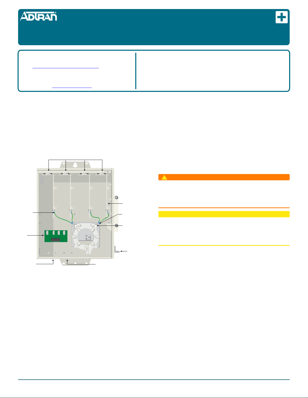
1. Route the Power Cable through the Power Entry Port located at the base
of the MDU Housing (see Figure 1).
2. Attach the two power leads (Pins 1 and 2) and if needed, the five alarm
status leads to the Power Connector (P/N: 3202007CN01-E).
3. Attach the Power Connector to the P1 Connector in the Power
Distribution Block.
ONT Installation Overview
There are two types of ONTs that can be installed in the MDU. Those are illus-
trated in Figure 3.
Installing an ONT consists of the following steps:
■Step 4a: Total Access 374 installation
■Step 4b: Total Access 352(H) or 362 installation
■Step 5: Connect Power to the ONTs
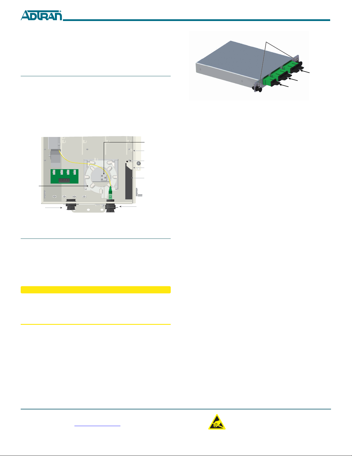
■Step 6: Route Internet Services Cables
Figure 3. ONTs
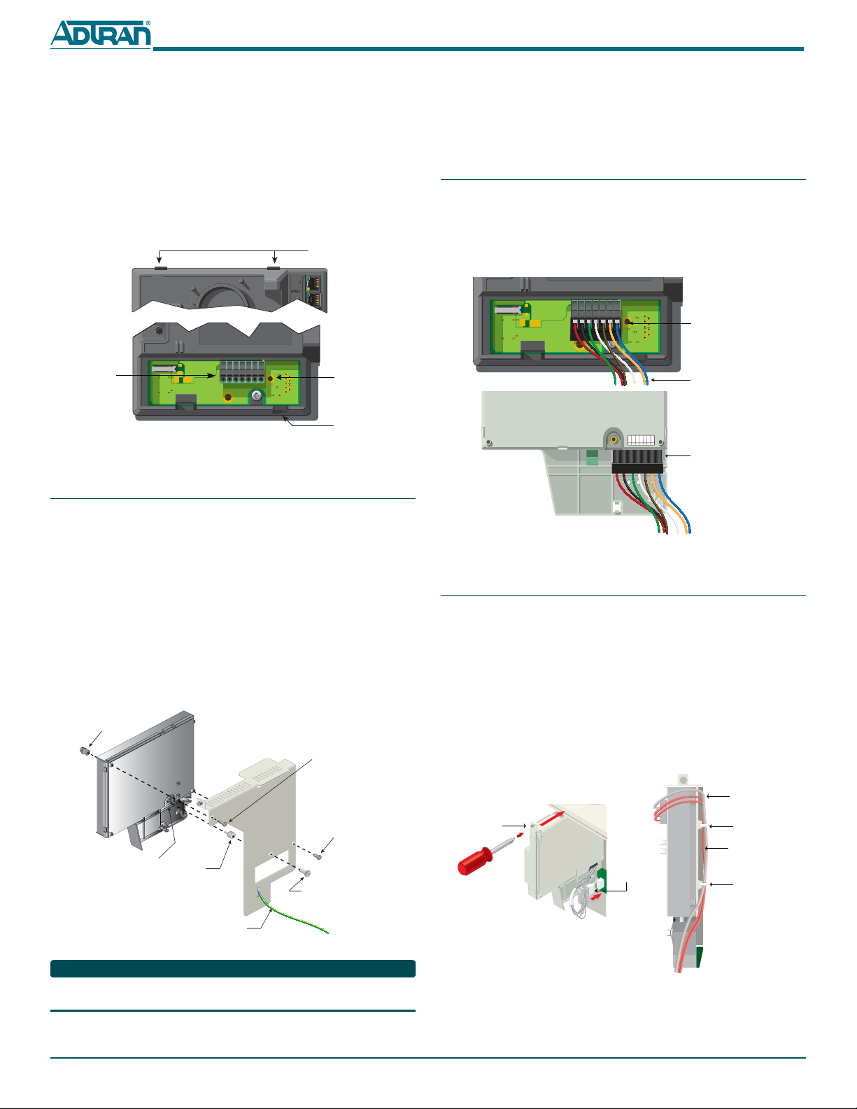
The ONT Support Bracket (P/N 3267140-E, Figure 4) is used by all ONTs when
attaching to the MDU Housing. These bracket are pre-installed in the MDU
Housing when shipped.
Figure 4. ONT Support Bracket
Step 4a: Total Access 374 installation
To install the Total Access 374 ONT, complete the following steps:
1. Refer to Figure 3 and loosen the “Telco Access Only” nut on the Total
Access 374 ONT Cover, and open the Cover.
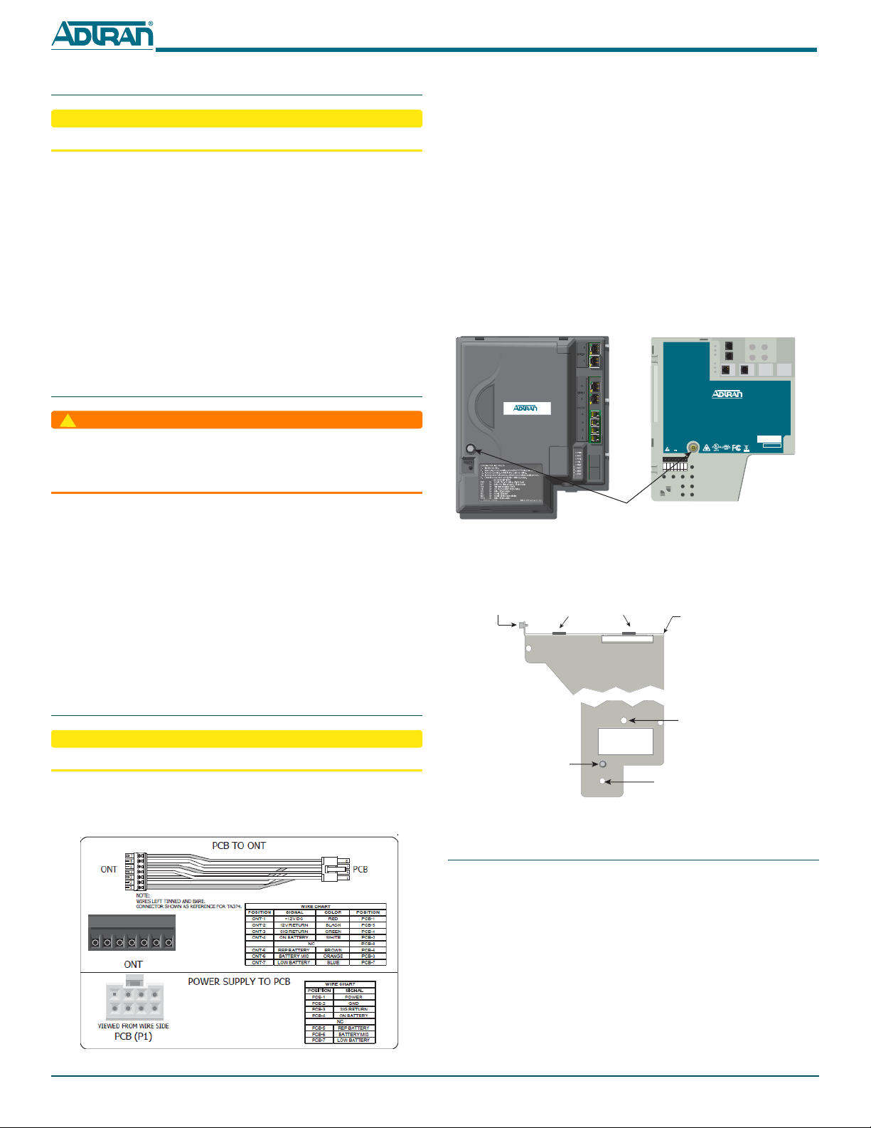
2. Refer to Figure 2 and attach the 7-Pin Plug (P/N: 3202007CN00-E) to the
Cable Assembly (P/N: 3125P135-E) per the WIRE CHART in Figure 2.
3. Insert the Cable Assembly in to the ONT Circuit Card Power Connector
illustrated in Figure 5.
4. Refer to Figure 1 and loosen the Bracket Mounting Screw holding the
Support Bracket to the MDU Housing. Remove the Support Bracket.
5. Align the ONT Mounting Tabs (Figure 4) on the ONT Support Bracket
with the ONT Bracket Mount Points on the ONT (Figure 5)
POTS 2
POTS 1
TELCO ACCESS
ETH 1
TOTAL ACCESS 351
1287701G1
12V , 1.25A
POWER
NETWORK STATUS
TELEPHONE TROUBLESHOOTING
1. Identify the bad line.
2. Disconnect the plug from the appropriate POTSjack and plug
any working telephone into that jack.
If the telephone works, there is a problem inside the house.
If the telephone does not work, contact your service provider.
3. Removethe telephone and replace the plug into the POTS jack.
4. Close the unit.
TEL. NUMBER
TIP/RING
+12VDC
12VRTN
SIGRTN
ONBAT
REPBAT
BATMIS
LOWBAT
7654321
Total Access 374 Total Access 352, 352H or 362
“Telco Access
Only” Nut
Bracket Mounting
Rail
ONT Mounting TabsBracket Mounting
Screw
Total Access 352, 352H and
362 ONTs Circuit Card
Mounting Point
Total Accss 374 ONT Mounting Point
PEM Nut for ground
wire connection
Step 1: Mount the MDU
CAUTION
!
The MDU should only be installed by qualified service personnel.
Consideration should be given to proper clearances for opening the MDU
door. Ensure that the door can be opened completely.
To mount the MDU, complete the following steps:
1. For outdoor installation, choose a vertical surface near an approved
ground, but away from down spouts, permanent water sprinklers, or
other water sources.
2. Use the top and bottom external mounting holes as a template to mark
fastener locations. Use a level to ensure the unit is level and the door will
open and close properly.
3. Pre-drill the marked locations and install two, 5/16 or 3/8-inch diameter
lag bolts that are appropriate to secure the MDU to the mounting
surface. The MDU housing with four ONTs, and associated cabling will
weigh approximately 25 pounds.
4. Mount the MDU.
Step 2: Ground the MDU
WARNING
!
Use extreme care when attaching the ground connectors to the utility (earth)
ground rod. If the ground is interrupted or disturbed in any way, an unsafe
condition will exist. Refer to the National Electrical Code (NEC) and state and
local codes for details on grounding requirements.
Refer to Figure 1 to ground the MDU.
1. Strip 5/8 of an inch of insulation from a 6 AWG ground wire and crimp
the grounding lug (P/N 3198001PN21-E) to the wire using the appropri-
ate crimping tool (i. e., Burndy Type Y35).
2. Attach the Ground Lug at the right-rear of the MDU housing with 2
Lock Washers (P/N 3284018-E) and 2 Screws (P/N 327611028-E).
a. Apply antioxidant to all grounding surfaces.
b. Attach ground lug with two #10 lock washers and two,
10-32 x 3/8-inch machine screws.
c. Torque the screws to 24 inch/pounds.
3. Apply the appropriate anti-oxidant and connect the opposite end of the
ground wire to a reliable earth ground.
Step 3: Connect Power to MDU
CAUTION
!
Do not turn the power source on until the MDU installation is complete.
To connect power to the MDU, refer the Power Distribution Block (P1) in
Figure 1, the Wire Chart and PCB (P1) portion of Figure 2 and complete the
following steps:
Figure 2. Power Distribution
1 2 3 4 5 6 7
4 3 2 1
8 7 6 5
61287733F1-22E 3
6. Refer to Figure 5 and insert the 10-32 x 3/8 inch machine screw through
the Circuit Card Mounting Point and secure to the standoff on the ONT
Support Bracket.
7. Refer to Figure 3, close the Cover and tighten the “Telco Access Only”
nut.
8. Refer to Figure 4 and align the ONT and Support Bracket Mounting
Rails with the guide rails on the MDU housing. Slide the unit in to the
MDU Housing.
9. If you are going to connect POTS, or Ethernet cables now, refer toStep 6:
Route Internet Services Cables. Otherwise, secure the ONT and Support
Bracket to the MDU Housing.
Figure 5. Total Access 374 Mounting Locations
Step 4b: Total Access 352(H) or 362 installation
To install either the Total Access 352(H) or 362 ONT, complete the following
steps:.
1. Attach the 7-Pin Connector (P/N: 3196007PN03-E) to the Cable Assem-
bly (P/N 3125P135-E) per Figure 2.
2. Refer to Figure 1 and loosen the screw holding the Support Bracket to
the MDU Housing, and remove the Support Bracket from the MDU
Housing.
3. Refer to Figure 6 and align the Standoff Nut/Screw with the Rear of the
“Teleco Access Only” Connector and the Support Bracket.
4. Attach the Support Bracket to the ONT by inserting a #10-16 Plastite
Screw (P/N 327600205-E) through the upper-left side and lower-right
side of the Support Bracket and into the ONT and tighten. Ensure the
Standoff is still aligned correctly.
Figure 6. Total Access 352 or 362 Mounting Locations
NOTE
In Figure 6, the ground wire is 24” long and is factory installed. You should not
need to remove it to install the ONTs.
Circuit Card
Mounting Point
ONT Bracket
Mounting Points
ONT Circuit Card
Power Connector
Power Connector
Cable Routing Port
Standoff
Nut/Screw
(P/N 3274332-E)
Rear of “Telco
Access Only”
Connector
10-32 x 3/8 Screw
(P/N 327611028-E)
Access Nut
8-18 Plastite Screw
(P/N 327600205-E)
8-18 Plastite Screw
(P/N 327600205-E)
Ground Wire
5. Refer to Figure 4 and align the ONT and Bracket Mounting Rails with
the guide rails on the MDU housing.
6. If you are going to connect POTS, or Ethernet cables now, refer toStep 6:
Route Internet Services Cables. Otherwise, secure the ONT and Support
Bracket to the MDU Housing.
Step 5: Connect Power to the ONTs
To connect power to the ONTs, complete the following steps:
1. Refer to Figure 1 and Figure 7 and connect the PCB end of the Power
Cable from the ONT to the P2 connector on the Power Distribution
Block located at the back of the MDU Housing. Cables should be routed
as illustrated in Figure 8. As additional ONTs are installed, connect the
Power Cable to the P3, P4 and P5 connectors respectively.
Figure 7. Power Connections
Step 6: Route Internet Services Cables
To route the Services Cables, complete the following steps:
1. Refer to Figure 1 and route the required number of POTS and Ethernet
cables through the Fiber Entry Point located at the base of the MDU
Housing.
2. Refer to Figure 8 and loosen the screw that holds the Support Bracket
and ONT to the MDU Housing.
3. Connect the POTS and Ethernet cables to the ONT and route as shown
in Figure 8 and tie wrap as necessary.
4. Refer to Figure 4 and align the ONT and Bracket Mounting Rails with
the guide rails on the MDU housing.
5. Secure the ONT and Support Bracket to the MDU Housing.
Figure 8. Connecting ONTs
+ 12VDC
12V RTN
SIG RTN
ON BAT
REPBAT
BATMIS
LOW BAT
7654321
Total Access 352(H) and 362
ONT Power Connector
(supplied with ONT)
Back of Electronics Module
Total Access 374 ONT
Power Connector
Cable Assembly
(P/N: 3125P135-E)
Ethernet Drop
(Orange)
POTS Drop
(Gray)
Tie Wrap Anchor
Point
Tie Wrap Anchor
Point
Note: Color of POTS and
Ethernet Drops for clarity
purposes only.
Note: POTS and Ethernet
cables removed for clarity.
Power Cable
“PCB TO ONT”
Phillips Screw and
Support Bracket
Warranty: ADTRAN will replace or repair this product within the warranty period if it does not
meet its published specifications or fails while in service. Warranty information can
be found online at www.adtran.com/warranty.
Trademarks: Brand names and product names included in this document are trademarks,
registered trademarks, or trade names of their respective holders.
©2016 ADTRAN, Inc. All Rights Reserved. *61287733F1-22E*
OPTIONAL INSTALLATIONS
The following are optional installations available for the MDU:
■Optitap Installation
■Fiber Splitter Installation
Opti-Tap Installation
If the MDU is equipped with an Opti-Tap Connector, refer to Figure 9 and
perform the following steps:
1. Secure the Opti-Tap Connector to the housing as shown.
2. Clean each end of the fiber jumper cable using standard optical cleaning
procedures and techniques.
3. Connect one end of the fiber jumper to the green SC connector on the
bottom of the Electronics Module just to the left of the Standoff.
4. Connect the other end to the Opti-Tap Connector.
Figure 9. OptiTap Installation
Fiber Splitter Installation
If required, install the Fiber Splitter (P/N 1187734G1) by completing the
following steps:
1. Refer to Figure 10 and remove the Mounting Plungers from the Fiber
Splitter.
2. Refer to Figure 9 and position the fiber Splitter against the inside of the
MDU Housing below the Fiber Mounting bracket and secure using the
Mounting Plungers.
CAUTION
!
LASER RADIATION
Do not view directly with optical instruments.
The ONT devices used with this product contain laser emitting modules. Refer
to the ONT’s documentation and labeling for any special requirements related
to the laser module.
3. Remove dust covers from only those connectors required on the fiber
Splitter.
4. Clean each optical connection using appropriate optical cleaning
procedures and techniques.
5. Refer to Figure 9 and connect the incoming fiber to the PON port on the
Fiber Splitter. If the OptiTap is being used, connect the fiber from the
OptiTap to the PON port on the Fiber splitter.
6. Connect a fiber cable to one of the ONT ports on the Fiber Splitter and
the other to the fiber connector on the ONT.
7. Repeat steps 3, 4 and 6 for each additional ONT.
F1
DSL/POTS 25-48
F2
F3
F4
Opti-Tap Connector
and Strain Relief
(for reference only)
FiberSplitter
(for reference only)
Fiber Splitter
Mounting Bracket
Mounting Plunger
Fiber Routing
Clips
Strain Relief
(for reference only)
Fiber Routing
Tray (Included)
Strength Member
Clamp
Figure 10. Fiber Splitter Installation
8. Tie wrap all fiber cables (use the Fiber Routing Clips above the Fiber
Splitter as shown in Figure 9) and ensure all ONTs are functioning
properly before closing and securing the MDU housing door.
Provisioning Options
Refer to the appropriate GPON OLT Installation and Maintenance Guide to
provision the OLTs in the MDU.
MAINTENANCE
The MDU does not require routine hardware maintenance for normal
operation. ADTRAN does not recommend that repairs be attempted in the
field. Repair services may be obtained by returning the defective unit to
ADTRAN. Refer to the warranty for further information. Field support for
software is provided through upgrade facilities.
SPECIFICATIONS
Specifications for the MDU are as follows:
■Electrical
♦Maximum Input voltage: 10.5 VDC to 14 VDC
♦Input Power: 100 watts
■Physical
♦Height: 20.0 inches
♦Width: 14.0 inches
♦Depth: 9.5 inches
♦Weight: 25 pounds depending on number of ONT modules
■Environmental
♦Maximum operating temperature: –40°C to +46.1°C
♦Maximum storage temperature: –40°C to +85°C
♦Relative humidity: 95% non condensing
SAFETY AND REGULATORY COMPLIANCE
For Safety and Regulatory Compliance Notice information refer to the Total
Access 480 MDU Safety and Regulatory Compliance Notice (P/N 61287733F1-17).
ONT
Mounting Plungers
ONT
PON
C A U T I O N
C A U T I O N
!
SUBJECT TO ELECTROSTATIC DAMAGE
OR DECREASE IN RELIABILITY.
HANDLING PRECAUTIONS REQUIRED.
ADTRAN CUSTOMER CARE:
From within the U.S. 1.800.726.8663
From outside the U.S. +1 256.963.8716
PRICING AND AVAILABILITY 1.800.827.0807

This manual suits for next models

1

Other ADTRAN Network Hardware manuals

ADTRAN TSU LT User manual

ADTRAN

ADTRAN TSU LT User manual

ADTRAN SHDSL V.35 LTU User manual

ADTRAN

ADTRAN SHDSL V.35 LTU User manual

ADTRAN ATM Mini-DSLAM User manual

ADTRAN

ADTRAN ATM Mini-DSLAM User manual

ADTRAN SDX 611 GPON SFU ONT User manual

ADTRAN

ADTRAN SDX 611 GPON SFU ONT User manual

ADTRAN TSU LT User manual

ADTRAN

ADTRAN TSU LT User manual

ADTRAN 1200630L1 User manual

ADTRAN

ADTRAN 1200630L1 User manual

ADTRAN 1203060L1 User manual

ADTRAN

ADTRAN 1203060L1 User manual

ADTRAN TA 900 User manual

ADTRAN

ADTRAN TA 900 User manual

ADTRAN NetVantaE1/FE1 User manual

ADTRAN

ADTRAN NetVantaE1/FE1 User manual

ADTRAN ISU 2X64 User manual

ADTRAN

ADTRAN ISU 2X64 User manual

ADTRAN Total Access 374 Product manual

ADTRAN

ADTRAN Total Access 374 Product manual

ADTRAN Smart 16e Shelf User manual

ADTRAN

ADTRAN Smart 16e Shelf User manual

ADTRAN DDM+ HTU-C M User manual

ADTRAN

ADTRAN DDM+ HTU-C M User manual

ADTRAN 1442390G1 User manual

ADTRAN

ADTRAN 1442390G1 User manual

ADTRAN NetVanta 1224 Instruction Manual

ADTRAN

ADTRAN NetVanta 1224 Instruction Manual

ADTRAN DE-4E Instruction Manual

ADTRAN

ADTRAN DE-4E Instruction Manual

ADTRAN ATLAS 550 User manual

ADTRAN

ADTRAN ATLAS 550 User manual

ADTRAN T200 H2TU-R Instruction Manual

ADTRAN

ADTRAN T200 H2TU-R Instruction Manual

ADTRAN HTU-C User manual

ADTRAN

ADTRAN HTU-C User manual

ADTRAN 6540 Product manual

ADTRAN

ADTRAN 6540 Product manual

ADTRAN ISU 128 User manual

ADTRAN

ADTRAN ISU 128 User manual

ADTRAN Total Access DSLAM 16-Port ADSL2+ Access Module... User manual

ADTRAN

ADTRAN Total Access DSLAM 16-Port ADSL2+ Access Module... User manual

ADTRAN 401 1 GE Micro ONT User manual

ADTRAN

ADTRAN 401 1 GE Micro ONT User manual

ADTRAN DSX 1 User manual

ADTRAN

ADTRAN DSX 1 User manual

Popular Network Hardware manuals by other brands

Sentry360 sentryEdge NVR manual

Sentry360

Sentry360 sentryEdge NVR manual

Tomar Strobecom II 4140 user guide

Tomar

Tomar Strobecom II 4140 user guide

TelcoBridges Tmedia TMG5800 Quick installation guide

TelcoBridges

TelcoBridges Tmedia TMG5800 Quick installation guide

Cerio OW-400 A1 user manual

Cerio

Cerio OW-400 A1 user manual

Pepwave Surf AP 200-X installation guide

Pepwave

Pepwave Surf AP 200-X installation guide

Austin Hughes CyberView MU-IP1613 user manual

Austin Hughes

Austin Hughes CyberView MU-IP1613 user manual

KonzeSys KZ-NP6000 PLUS user manual

KonzeSys

KonzeSys KZ-NP6000 PLUS user manual

Huawei SmartAX MA5616 Configuration guide

Huawei

Huawei SmartAX MA5616 Configuration guide

LEGRAND 369420 instruction manual

LEGRAND

LEGRAND 369420 instruction manual

Patton electronics 3060/X.21 Installation and operation manual

Patton electronics

Patton electronics 3060/X.21 Installation and operation manual

ettus USRP-2900 Getting started

ettus

ettus USRP-2900 Getting started

SonicWALL PRO 4100 Getting started guide

SonicWALL

SonicWALL PRO 4100 Getting started guide

Siemens RUGGEDCOM WIN5237-IS installation guide

Siemens

Siemens RUGGEDCOM WIN5237-IS installation guide

Xinje XD Series user manual

Xinje

Xinje XD Series user manual

ELVA-1 PPC-10G Series Installation and user manual

ELVA-1

ELVA-1 PPC-10G Series Installation and user manual

Cambium Networks cnWave 5G Fixed Operation and Troubleshooting Guide

Cambium Networks

Cambium Networks cnWave 5G Fixed Operation and Troubleshooting Guide

RF-Link AWS-5832-VSR user manual

RF-Link

RF-Link AWS-5832-VSR user manual

NSFOCUS 100M WAF NX3 Series installation guide

NSFOCUS

NSFOCUS 100M WAF NX3 Series installation guide

manuals.online logo
manuals.online logoBrands
  • About & Mission
  • Contact us
  • Privacy Policy
  • Terms and Conditions

Copyright 2025 Manuals.Online. All Rights Reserved.