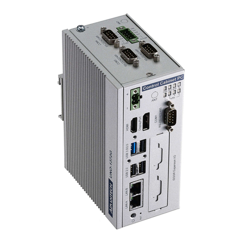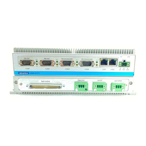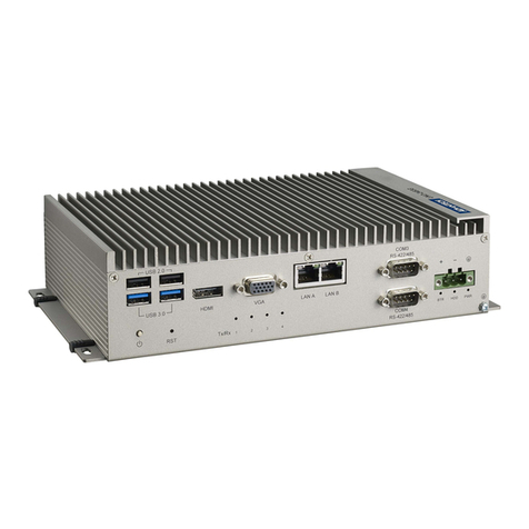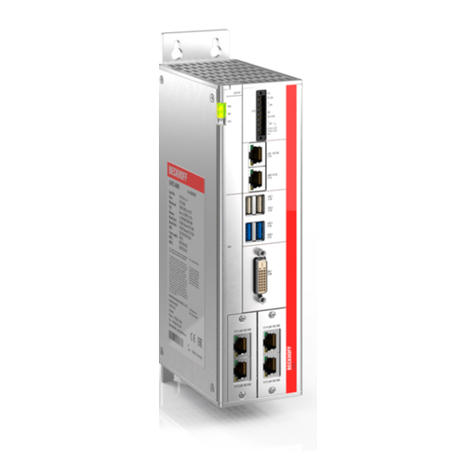
v UNO-238 User Manual
Product Warranty (2 years)
Advantech warrants the original purchaser that all of its products will be free from
defects in materials and workmanship for two years from the date of purchase.
This warranty does not apply to any products that have been repaired or altered by
persons other than repair personnel authorized by Advantech, or products that have
been subject to misuse, abuse, accident, or improper installation. Advantech
assumes no liability under the terms of this warranty as a consequence of such
events.
Because of Advantech's high quality-control standards and rigorous testing, most
customers never need to use our repair service. If an Advantech product is defective,
it will be repaired or replaced at no charge during the warranty period. For out-of-war-
ranty repairs, customers are billed according to the cost of replacement materials,
service time, and freight. Please consult your dealer for more details.
If you suspect that your product is defective product, follow the steps outlined below.
1. Collect all the information about the problem encountered (for example, CPU
speed, Advantech products used, other hardware and software used, etc.). Note
anything abnormal and list any onscreen messages displayed when the prob-
lem occurs.
2. Call your dealer and describe the problem. Please have your manual, product,
and any helpful information readily available.
3. If your product is diagnosed as defective, obtain a return merchandize authori-
zation (RMA) number from your dealer. This allows us to process your return
more quickly.
4. Carefully pack the defective product, a completed Repair and Replacement
Order Card, and a proof of purchase date (such as a photocopy of your sales
receipt) into a shippable container. Products returned without a proof of pur-
chase date are not eligible for warranty service.
5. Write the RMA number clearly on the outside of the packaging, and ship the
package prepaid to your dealer.
Declaration of Conformity
CE
This product has passed the CE test for environmental specifications when shielded
cables are used for external wiring. We recommend the use of shielded cables. This
type of cable is available from Advantech. Please contact your local supplier for
ordering information.
FCC Class A
This equipment has been tested and found to comply with the limits for a Class A dig-
ital device, pursuant to part 15 of the FCC Rules. These limits are designed to pro-
vide reasonable protection against harmful interference when the equipment is oper-
ated in a commercial environment. This equipment generates, uses, and can radiate
radio frequency energy and, if not installed and used in accordance with the instruc-
tion manual, may cause harmful interference to radio communications. Operation of
this equipment in a residential area is likely to cause harmful interference. In such
cases, users are required to correct the interference at their own expense.
警告使用者:這是甲類資訊產品,在居住的環境中使用時, 可能會造成射頻干擾,在
這種情況下,使用者會被要求採取某些適當對策。
