manuals.online logo
Brands
  1. Home
  2. •
  3. Brands
  4. •
  5. aFe Power
  6. •
  7. Automobile Accessories
  8. •
  9. aFe Power advanced FLOW engineering User manual

aFe Power advanced FLOW engineering User manual

®
advanced FLOW engineering
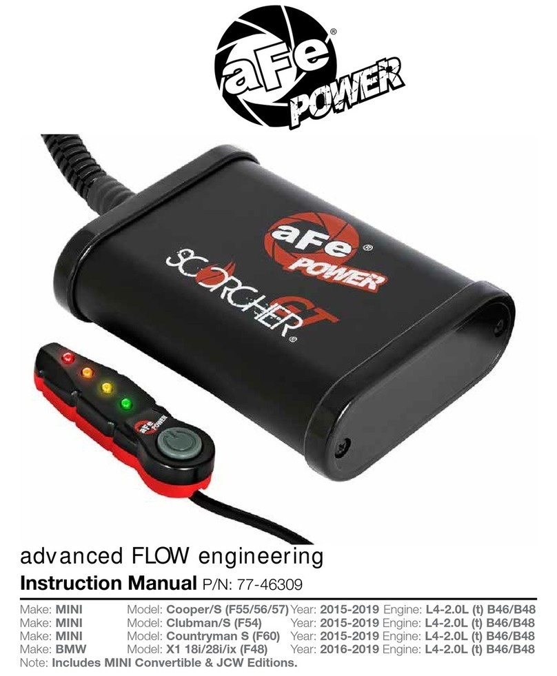
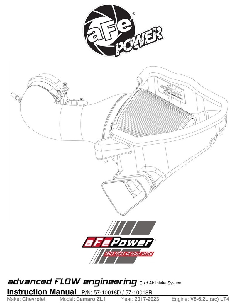
Instruction Manual P/N: 77-46310
Make: BMW Model: M3/M4 (F80) Year: 2015-2018 Engine: L6-3.0L (tt) S55
Make: BMW Model: M4 (F82/F83) Year: 2015-2020 Engine: L6-3.0L (tt) S55
Make: BMW Model: M2 Competition (F87) Year: 2019-2020 Engine: L6-3.0L (tt) S55
Note: Includes M3 CS, M4 CS & GTS Models.
®
Label Qty. Description Part Number
A 1 Module R77-46310
B 1 LED Switch 05-70029
C 2 Velcro (2 Inches) 05-01244
D 4 Cable Ties 05-60167
Note: Legal in California for use on race vehicles only. The use of this device on vehicles used on public
streets or highways is strictly prohibited in California and others states that have adopted California
emission regulations.
• Please read the entire instruction manual before proceeding.
• Ensure all components listed are present.
• If you are missing any of the components, call customer support at 951-493-7100.
• Ensure you have all necessary tools before proceeding.
• Do not attempt to work on your vehicle when the engine is hot.
• Disconnect the negative battery terminal before proceeding.
• Retain factory parts for future use.
Page 2
aFepower.com
Page 3
A
B
CD
®
Refer to Figure A for Step 1.
Step 1: Before installing your aFe module, you will have to place your vehicles ECU in sleep mode. In
order to do this you will need to do the following:
- If the engine is cold, open the hood, close the doors lock the car and wait 30 seconds.
- If the engine is warm, open the hood, close the doors lock the car and wait 20 minutes.
- If the engine is warm and you can’t wait 20 minutes, disconnect the battery.
REMOVAL
Page 4
Figure A
Refer to Figure B for Steps 2-5.
Step 2: Locate the TMAP 1 and MAP sensors 2 . The TMAP sensor is located driver side on charge
pipe, the MAP sensor is located on top of the intake manifold, behind the charge-air cooler and
under the expansion tank.
Step 3: Remove the push clip on the driver side windshield cover. 3
Step 4: Unlock the three 10mm nuts retaining the windshield cover and remove. 4
Step 5: Remove the two T27 screws off the top expansion tank and pop off grommet.
REMOVAL
Page 5
4
23
1
4 4
aFepower.com
Figure B
Refer to Figure C for Steps 6-7.
Step 6: Pass the aFe module harness through frame brace.
Step 7: Pop off the trim seal of the frame brace to allow more space.
Figure C
Page 6
REMOVAL
®
Step 8: Disconnect the MAP sensor, by pressing down on the locking tab and sliding the connector out
of the sensor.
Step 9: Locate the MAP sensor jumper harness on the aFe module. This is the longer harness with 4
wires in the connectors. Plug the female connector of the module into the MAP sensor, then the
male connector of the module into the female connector of the engine harness.
Note: Make sure connections are fully engaged. Usually, connectors make a snapping
sound when fully engaged.
Refer to Figures D for Steps 8-9.
Figure D
Page 7
INSTALL
aFepower.com
Page 8
Refer to Figure E for Steps 10-11.
Step 10: Locate and disconnect the TMAP sensor, by pressing down on the locking tab and sliding the
connector out of the sensor.
Step 11: Locate the TMAP sensor jumper harness on the aFe module. This is the shorter harness
with 3 wires in the connectors. Plug the female connector of the module into the
TMAP sensor, then plug the male connector of the module into to the female connector of the
engine harness.
Figure E
INSTALL
®
aFepower.com
Page 9
Refer to Figure F for Steps 12-13.
Step 12: Carefully route the switch cable behind steering wheel cover.
Step 13: Mount the Switch on an open, flat surface
Figure F
INSTALL
Page 10
Refer to Figure G for Steps 14-16.
Step 14: Remove the two 10mm nuts holding the foot trim panel.
Step 15: Route the switch cable through firewall and into the engine bay. Follow the main harness
through the grommet into the firewall. Plug the end of the cable to the module.
Step 16: Re-install foot trim panel.
Figure G
INSTALL
®
Page 11
Refer to Figure H for Steps 17-18.
Step 17: Mount the module in a safe location, using the supplied Velcro strip. Then, secure the wires and
module away from any extreme heat and moving parts, with the provided ties.
Step 18: Re-install the windshield cover and expansion tank. Refer to steps 2-4.
Note: Make sure connections are fully engaged. Usually, connectors make a snapping
sound when fully engaged.
Figure H
INSTALL
aFepower.com
Page 12
Refer to Figure H for Step 19.
Step 19: When turning on the vehicle, each LED will flash. It will stop at its last setting.
The LED on the switch represents the different level of power.
• Green LED: Stock
• Yellow LED: Sport
• Orange LED: Sport+
• Red LED: Race
Use the grey button to select the desired setting. Power adjustments can be done at any
moment.
Thank you for choosing aFe POWER!
Figure H
INSTALL
®
Page left blank intentionally
aFepower.com
Page left blank intentionally
aFepower.com
Page left blank intentionally
aFepower.com
advanced FLOW engineering, inc.
252 Granite Street Corona, CA 92879
TEL: 951.493.7100 TECH: 951.493.7134
E-Mail:Tech@aFepower.com P/N: 06-80880
®

Other manuals for advanced FLOW engineering

1

Other aFe Power Automobile Accessories manuals

aFe Power Momentum GT User manual

aFe Power

aFe Power Momentum GT User manual

aFe Power Magnum FORCE User manual

aFe Power

aFe Power Magnum FORCE User manual

aFe Power Scorpion 79-21005L User manual

aFe Power

aFe Power Scorpion 79-21005L User manual

aFe Power 46-20299-B User manual

aFe Power

aFe Power 46-20299-B User manual

aFe Power SCORCHER 77-44008 User manual

aFe Power

aFe Power SCORCHER 77-44008 User manual

aFe Power 46-70022 User manual

aFe Power

aFe Power 46-70022 User manual

aFe Power 54-12208 User manual

aFe Power

aFe Power 54-12208 User manual

aFe Power SCORPION 79-21003L User manual

aFe Power

aFe Power SCORPION 79-21003L User manual

aFe Power 77-47001 User manual

aFe Power

aFe Power 77-47001 User manual
aFe Power 46-71180A User manual

aFe Power

aFe Power 46-71180A User manual

aFe Power 77-86318 User manual

aFe Power

aFe Power 77-86318 User manual

aFe Power 77-83028 User manual

aFe Power

aFe Power 77-83028 User manual

aFe Power Momentum hd User manual

aFe Power

aFe Power Momentum hd User manual

aFe Power 54-82039 User manual

aFe Power

aFe Power 54-82039 User manual

aFe Power 46-70049 User manual

aFe Power

aFe Power 46-70049 User manual

aFe Power 52-10001D User manual

aFe Power

aFe Power 52-10001D User manual

aFe Power 440-401006-N User manual

aFe Power

aFe Power 440-401006-N User manual

aFe Power advanced FLO engineering User manual

aFe Power

aFe Power advanced FLO engineering User manual

aFe Power SCORCHER GT 77-47004 User manual

aFe Power

aFe Power SCORCHER GT 77-47004 User manual

aFe Power 50-70007D User manual

aFe Power

aFe Power 50-70007D User manual

aFe Power Scorcher User manual

aFe Power

aFe Power Scorcher User manual

aFe Power QUANTUM 53-10005D User manual

aFe Power

aFe Power QUANTUM 53-10005D User manual

aFe Power Quantum 2500 User manual

aFe Power

aFe Power Quantum 2500 User manual

aFe Power 77-43023 User manual

aFe Power

aFe Power 77-43023 User manual

Popular Automobile Accessories manuals by other brands

Warn 63290 installation instructions

Warn

Warn 63290 installation instructions

Velleman CARS4500 user manual

Velleman

Velleman CARS4500 user manual

Thule Tracker TK4 installation instructions

Thule

Thule Tracker TK4 installation instructions

Eibach ANTI-ROLL-KIT AS41-55-019-01-FA installation instructions

Eibach

Eibach ANTI-ROLL-KIT AS41-55-019-01-FA installation instructions

Kuda-Phonebase 295240 Installation instruction

Kuda-Phonebase

Kuda-Phonebase 295240 Installation instruction

ARKSEN 005-PBK-FH2-SD owner's manual

ARKSEN

ARKSEN 005-PBK-FH2-SD owner's manual

Prorack K1008 Fitting instructions

Prorack

Prorack K1008 Fitting instructions

G3 KRONO 240 manual

G3

G3 KRONO 240 manual

Canyon CNE-CCA05 quick guide

Canyon

Canyon CNE-CCA05 quick guide

Car Solutions v130418 installation manual

Car Solutions

Car Solutions v130418 installation manual

Broadfeet DWTO-711-32S installation instructions

Broadfeet

Broadfeet DWTO-711-32S installation instructions

Caltrend FD332 installation instructions

Caltrend

Caltrend FD332 installation instructions

BMW 84 61 0 028 926 installation instructions

BMW

BMW 84 61 0 028 926 installation instructions

WeatherTech Child Car Seat Protector installation instructions

WeatherTech

WeatherTech Child Car Seat Protector installation instructions

Arkon SM514 user manual

Arkon

Arkon SM514 user manual

RBO RBO4038 product manual

RBO

RBO RBO4038 product manual

Prorack K561 Fitting instructions

Prorack

Prorack K561 Fitting instructions

Zendure Q7 user manual

Zendure

Zendure Q7 user manual

manuals.online logo
manuals.online logoBrands
  • About & Mission
  • Contact us
  • Privacy Policy
  • Terms and Conditions

Copyright 2025 Manuals.Online. All Rights Reserved.