manuals.online logo
Brands
  1. Home
  2. •
  3. Brands
  4. •
  5. AFRISO
  6. •
  7. Control Unit
  8. •
  9. AFRISO 17 100 00 User manual

AFRISO 17 100 00 User manual

This manual suits for next models

1

Other AFRISO Control Unit manuals

AFRISO WaterControl 01.1 User manual

AFRISO

AFRISO WaterControl 01.1 User manual

AFRISO VarioFox 24 User manual

AFRISO

AFRISO VarioFox 24 User manual

AFRISO MSS User manual

AFRISO

AFRISO MSS User manual

AFRISO MS Series User manual

AFRISO

AFRISO MS Series User manual

AFRISO ARV ProClick User manual

AFRISO

AFRISO ARV ProClick User manual

AFRISO ACU 2030 User manual

AFRISO

AFRISO ACU 2030 User manual

AFRISO KAV Series User manual

AFRISO

AFRISO KAV Series User manual

AFRISO MSW User manual

AFRISO

AFRISO MSW User manual

AFRISO CosiTherm UM User manual

AFRISO

AFRISO CosiTherm UM User manual

AFRISO WaterControl 01 User manual

AFRISO

AFRISO WaterControl 01 User manual

AFRISO Flow-Control Series User manual

AFRISO

AFRISO Flow-Control Series User manual

AFRISO TAS 03 User manual

AFRISO

AFRISO TAS 03 User manual

AFRISO DKH User manual

AFRISO

AFRISO DKH User manual

AFRISO ARV Vario ProClick User manual

AFRISO

AFRISO ARV Vario ProClick User manual

AFRISO KSG Magnum Series User manual

AFRISO

AFRISO KSG Magnum Series User manual

AFRISO CosiTherm F2A User manual

AFRISO

AFRISO CosiTherm F2A User manual

Popular Control Unit manuals by other brands

Seitz 14A80 user manual

Seitz

Seitz 14A80 user manual

Wilo RS485 Installation and operating instructions

Wilo

Wilo RS485 Installation and operating instructions

Becker CentralControl CC41 Commissioning Instruction

Becker

Becker CentralControl CC41 Commissioning Instruction

SICK CDB650 operating instructions

SICK

SICK CDB650 operating instructions

Panduit NetKey NKP5E88M Series installation instructions

Panduit

Panduit NetKey NKP5E88M Series installation instructions

MX Options Concentric Petite Fitting instructions

MX

MX Options Concentric Petite Fitting instructions

Clean Water Systems Fleck 2510 Installation & start?up guide

Clean Water Systems

Clean Water Systems Fleck 2510 Installation & start?up guide

Fairchild FSB44104A user guide

Fairchild

Fairchild FSB44104A user guide

LEGRAND Wattstopper LMIN-104 installation instructions

LEGRAND

LEGRAND Wattstopper LMIN-104 installation instructions

PMK ATT10BNCS instruction manual

PMK

PMK ATT10BNCS instruction manual

Tektronix TDS3FFT user manual

Tektronix

Tektronix TDS3FFT user manual

Woodward easYgen Technical manual

Woodward

Woodward easYgen Technical manual

Balluff BNI EIP-502-105-R015 user guide

Balluff

Balluff BNI EIP-502-105-R015 user guide

NXP Semiconductors TWR-LS1021A Getting started

NXP Semiconductors

NXP Semiconductors TWR-LS1021A Getting started

Advantech PCM-3117 Startup manual

Advantech

Advantech PCM-3117 Startup manual

Danfoss MCO 101 manual

Danfoss

Danfoss MCO 101 manual

Moons' Lin Engineering R701P user manual

Moons'

Moons' Lin Engineering R701P user manual

Aventics RV1 operating instructions

Aventics

Aventics RV1 operating instructions

manuals.online logo
manuals.online logoBrands
  • About & Mission
  • Contact us
  • Privacy Policy
  • Terms and Conditions

Copyright 2025 Manuals.Online. All Rights Reserved.

APPLICATION
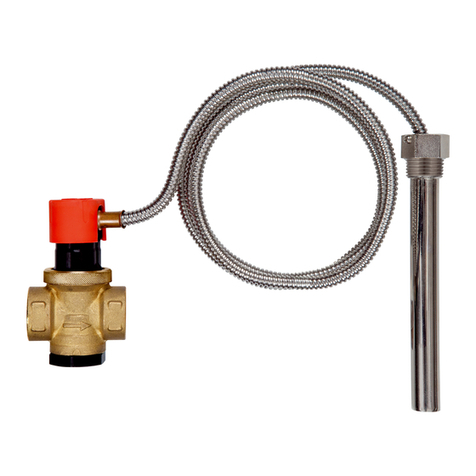
Used in heating and cooling systems with air source heat pump monoblock type. Mounted on the return
and supply pipe of the system, as close as possible to the heat pump outdoor unit, outside the building.
Protects the internal components of the heat pump and the system from damage due to freezing of the
medium in the system.
WORKING PRINCIPLE
In a system with a monoblock air source heat pump, during a loss of circulation (e.g., due to a power
failure), the medium in the installation may freeze at sub-zero ambient temperatures. The created ice can
damage the heat pump heat exchanger and other sensitive installation components. When the tempera-
ture of the medium in the system drops to 3°C, the thermostatic element inside the valve will open the
ow of the medium to the outside, preventing potential damage. When the temperature of the medium
rises above 4°C, the thermostatic element will automatically close the ow of medium from the system.
Fig. 1 VALVE CONSTRUCTION
Vacuum breaker
Valve body
Cartridge with thermostatic element
The product may only be installed, commissioned and dismantled by suitably qualied
and trained personnel.
Changes and modications carried out by unauthorised persons may result in danger
and are prohibited for safety reasons.
Risk of burns from hot medium - see the chapter MAINTENANCE.
Instruction manual 953.001.0159
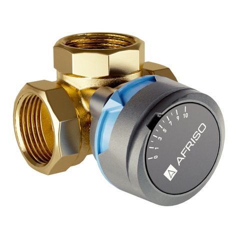
Anti-freeze valve AAV
Art.-No 17 100 00, 17 300 00
AFRISO Sp. zo.o.
Szałsza, ul. Kościelna 7
42-677 Czekanów
www.afriso.pl
Customer Service Team
phone: 32 330 33 55
fax 32 330 33 51
[email protected]
WARNING!
DIMENSIONS [mm]
Fig. 2 AAV 100 valve
58
124
83 41
G1ʺ
G1ʺ
Fig. 3 AAV 300 valve
58
124
83
G1¼ʺ
G1¼ʺ
1 2
41
Parameter Value / material
Opening temperature 3°C
Closing temperature 4°C
Accuracy ±1°C
Operating temperature range 0÷70 ° C
Ambient temperature range -30÷60°C
Operating pressure max 10 bar
Kvs (depending on the version) AAV 100 - 55 m3/h
AAV 300 - 70 m3/h
Connections (depending on the version) AAV 100 - G1”
AAV 300 - G1¼”
Body material brass CW617N
Spring material stainless steel
Sealing material EPDM
CUSTOMER SATISFACTION
Customer satisfaction is our prime objective. Please contact us if you have any questions or problems
concerning our product: zok@afriso.pl, phone: 32 330 33 55.
WARRANTY
Product warranty in accordance with the general conditions of sale and delivery
APPROVALS AND CERTIFICATES
Anti-freeze valves AAV complies with the Pressure Directive PED 2014/68/EU and according to article 4.3
(sound engineering practice) must not wear the CE mark
MAINTENANCE
Warning! Maintenance operations should be done only after the installation will completely
cooled down.
The AAV valve is a completely maintenance-free. In case of water leaks through the vacuum breaker,
it is possible to replace it with a new one (Art.-Nr. 17 000 03). If the thermostatic cartridge malfunctions,
replace the cartridge together with the thermostatic element (for AAV 100 valve Art.-No. 17 000 01, for
AAV 300 valve (Art.-No 17 000 02). In order to replace the cartridge with the thermostatic element and/
or the vacuum breaker, rst disconnect the AAV valve from the rest of the system by closing the ow
on the nearest shut-off valves. Then unscrew the defective element from the valve and screw in a new
one.After the replacement is completed, open the shut-off valves and check the pressure in the system.
If necessery ll the instalation with medium.
MONTAGE
The AAV anti-freeze valve should be installed on the return and supply pipelines in a vertical position,
in the coldest part of the system (between the building wall and the outdoor unit of the heat pump).
For proper operation, the valve should not be thermally insulated and located near heat sources that
could negatively affect to its operation. In addition, the valves should not be mounted one above the
other. Between the valves should be min. 10 cm of horizontal clearance. The owing medium from the
upper valve, which will hit the valve located below may freeze and block the draining of the medium
properly through the lower valve. Do not mount the valve directly on the ground. Keep a min. 20 cm cle-
arance, so that the created ice does not block the drainage of water from the valve (Figure 4). The valve
should be shielded from the direct inuence of atmospheric conditions, which can lead to its incorrect
operation.
Fig. 4 MINIMAL DISTANCE BETWEEN THE BOTTOM OF THE VALVE AND THE GROUND
min. 20 cm
Created ice
Between the valve and the external unit of the heat pump, must not be any siphoned pipeline sections,
which can cause a disturbance in the outow of the medium from the system. In this case, the pipes may
not be fully drained and the protection against freezing will not be ensured (Figure 5). Lead the pipes
with a constant slope toward the valve (Figure 6). In order to minimize the impact of any impurities
on the proper operation of valves in the system, it is recommended to install a magnetic dirt separator
(Art.-No 77 180 00) and application of a corrosion inhibitor (Art.-No 90 700 00) in the installation.
Fig. 5 UNACCEPTABLE PIPE ROUTING DUE TO SIPHONED SECTIONS
Fig. 6 ACCEPTABLE INSTALLATION POSITION AND PIPE ROUTING IN THE SYSTEM
TECHNICAL DATA
DECOMMISSIONING, DISPOSAL
1. Dismount the product
2. To protect the environment, this product must not be disposed of together with normal household
waste. Dispose of the product in accordance with the local directives and guidelines.
Anti-feeze valves AAV consist of materials that can be recycled
3 4