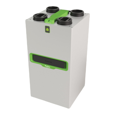
aldes InspirAIR Home Premium SC150 User manual

Page 1 of 41
InspirAIR® Home
Air purification for individual dwellings
Heat recovery ventilation
Description
Exploded views and Parts
Electrical wiring diagrams
Maintenance instructions
Repair guide
Intervention
guide
Version - March 2019
Air purification

Page 2 of 41

Page 3 of 41
Contents
1. General information...................................................................................................................................... 4
1.1 Related reference documents .................................................................................................................... 4
2. General description ...................................................................................................................................... 4
2.1 InspirAIR® Home Heat recovery ventilation system.................................................................................... 4
2.2 Typical example.......................................................................................................................................... 4
2.3 Product references and kit contents ........................................................................................................... 5
3. Exploded view and parts list........................................................................................................................ 6
3.1 Exploded view (Version 240/370 Premium right)........................................................................................ 6
3.2 Exploded view (Version 150 Premium right)............................................................................................... 7
3.3 Spare parts list............................................................................................................................................ 7
3.4 Options & Accessories ............................................................................................................................. 10
4. Electrical wiring diagrams ......................................................................................................................... 12
5. Maintenance instructions........................................................................................................................... 13
Definition of maintenance levels ........................................................................................................................ 13
List of tools and equipment ................................................................................................................................ 13
Maintenance operations guide ........................................................................................................................... 13
5.1 List of preventive maintenance operations InspirAir 240/370 ................................................................... 14
5.2 List of curative maintenance operations InspirAir 240/370 ....................................................................... 14
5.3 Operating procedures Inspirair 240/370 ................................................................................................... 15
5.4 List of preventive maintenance operations InspirAir 150 .......................................................................... 22
5.5 List of curative maintenance operations InspirAir 150 .............................................................................. 22
5.6 Operating procedures Inspirair 150 .......................................................................................................... 24
5.7 Repair guide ............................................................................................................................................. 32
5.5 Breakdown flow chart ............................................................................................................................... 33

Page 4 of 41
1.General information
1.1 Related reference documents
Document title
Reference
Installation and maintenance guide
11029515
Use and servicing manual
11027565
Classic keypad navigation manual
11027566
Premium keypad navigation manual
11027542
InspirAIR Home SC Modbus manual
11024829
2.General description
2.1 InspirAIR® Home Heat recovery ventilation system
In a heat recovery system, air is renewed mechanically through a
supply into living areas and exhaust from utility rooms (kitchen,
bathroom/shower, WC, cellar)
The soiled air extracted by the utility room outlets pass through a
heat recovery unit before being discharged outside.
The heat exchanger serves to recover the heat in the exhaust air
to pre-heat the incoming air.
2.2 Typical example
There are two possible installations:
Ceiling mounting Wall mounting

Page 5 of 41
2.3 Product references and kit contents
Description
Side
InspirAIR® Home
Classic
InspirAIR® Home
Modbus
InspirAIR® Home
Premium
InspirAIR® Home
SC150
Right
11023453
11023457
11023455
Left
11023454
11023458
11023456
InspirAIR® Home
SC240
Right
11023310
11023446
11023312
Left
11023311
11023447
11023313
InspirAIR® Home
SC370
Right
11023314
11023448
11023316
Left
11023315
11023449
11023317
InspirAIR Home® Classic (Modbus)
InspirAIR Home® Premium

Page 6 of 41
3.Exploded view and parts list
3.1 Exploded view (Version 240/370 Premium right)
1
4
5
6
2
3
7
8
9
9

Page 7 of 41
3.2 Exploded view (Version 150 Premium right)
3.3 Spare parts list
Reference
Description
Reference
Classic
Modbus
Premium
1
S/E CONDENSATE TRAY
SC150
11100764
OK
OK
OK
CONDENSATE TRAY SC240
RIGHT
11127734
OK
OK
OK
CONDENSATE TRAY SC240
LEFT
11127733
OK
OK
OK
CONDENSATE TRAY SC370
RIGHT
11127663
OK
OK
OK
CONDENSATE TRAY SC370
LEFT
11127662
OK
OK
OK
3
8
1
2
7
6
5
4

Page 8 of 41
Reference
Description
Reference
Classic
Modbus
Premium
2
S/E ELEC. BOARD SC150
11100765
OK
-
-
11100766
-
OK
OK
ELEC. BOARD SC240
11127578
OK
-
-
11127579
-
OK
OK
ELEC. BOARD SC370
11100521
OK
-
-
11100522
-
OK
OK
3
S/E CORE (V2)
SC150 / SC240/ SC370
11100771
-
-
OK
4
S/E Clockwise Motor SC150
11100759
OK
OK
OK
S/E Clockwise Motor SC240
11127750
OK
OK
OK
S/E Clockwise Motor SC370
11127679
OK
OK
OK
5
S/E ANTI-CLOCKWISE
MOTOR SC150
11100760
OK
OK
OK
S/E ANTI-CLOCKWISE
MOTOR SC240
11127745
OK
OK
OK
S/E ANTI-CLOCKWISE
MOTOR SC370
11127674
OK
OK
OK

Page 9 of 41
Reference
Description
Reference
Classic
Modbus
Premium
6
INSPIRAIR SC150 HEAT
EXCHANGER
11100772
OK
OK
OK
S/E HEAT EXCHANGER
SC240
11127719
OK
OK
OK
S/E HEAT EXCHANGER
SC370
11127696
OK
OK
OK
7
S/E BY-PASS SC150
11100763
OK
OK
OK
S/E BY-PASS SC240
11127766
OK
OK
OK
S/E BY-PASS SC370
11127695
OK
OK
OK
8
S/E COVER SC150
11100768
OK
OK
-
11100769
-
-
OK
COVER SC240
11127759
OK
OK
-
11127760
-
-
OK
COVER SC370
11127688
OK
OK
-
11127689
-
-
OK
9
Please refer to the user manual for the lters
-
INSTALL. KEYPAD
SC240/SC370 RIGHT
11127577
OK
OK
-
INSTALL. KEYPAD
SC150/SC240/SC370 LEFT
11127563
OK
OK
-
-
COMPLETE HARNESS KIT
SC150
11100767
OK
OK
OK
COMPLETE HARNESS KIT
SC240/370
11127599
OK
OK
OK

Page 10 of 41
*Possibility of using the SC370 version as centre-to-centre distance of connections identical but outside dimensions greater.
3.4 Options & Accessories
Filters: please refer to the user manual or the Aldes website
Product
Description
InspirAIR®
Home SC150
InspirAIR®
Home SC240
InspirAIR®
Home SC370
"Blind" nishing trap
11023321
11023321
11023321
"Porthole" nishing trap
11023440
11023440
11023440
Cradle
11023322
11023322
11023322
Distribuon box fan
-*
11023323
11023327
Duct cover
-
300mm
11023324
300mm
11023328
-
500mm
11023398
500mm
11023399
-
Finish
11023426
Finish
11023427
Bahia Curve terminals
11015490
11015490
11015490
BCA Bus pre-heang coil
11023225
11023225
11023225
CO2 sensor
11017090
11017090
11017090
Calogaine seal connector
D160
Built in
11023209
11023209
Male galvanised connector
with seals
-
11098163
11098163
AldesConnectBoxTM
11023386
11023386
11023386
2-speed remote control -
push buon (wired)
11026011
11026011
11026011

Page 11 of 41
Product
Description
InspirAIR®
Home SC150
InspirAIR®
Home SC240
InspirAIR®
Home SC370
3-speed remote control
(wired)
11023065
11023065
11023065
4-speed remote control
(wired)
11023334
11023334
11023334

Page 12 of 41
4.Electrical wiring diagrams
Inspirair home SC150 Classic, SC240 Classic and SC370 Classic board:
Inspirair home SC150 Premium / Modbus; SC240 Premium / Modbus et SC370
Premium / Modbus board:
Aldes Ibus
Kitchen push button
0-10V input
Motor control 0-10 V
(fresh air)
Temperature sensors
Motor supply
General supply
Motor control 0-10 V
(discharge)
Motor supply
Installer keypad
By-pass
USB port
By-pass
USB port
Temperature sensors
Pressure tap
Motor control 0-10 V
(fresh air)
Internal coil control
Motor supply
Motor supply
General supply
Motor control 0-10 V
(discharge)
Control core
MODBUS
Aldes Ibus
Kitchen push button
0-10V input

Page 13 of 41
5.Maintenance instructions
•Check that the installation complies with the recommendations provided ("Installation Manual")
•Check that the unit is configured to suit the installation ("Configuration Manual")
•Check that all exhaust ducts and terminals are correctly connected. Flexible ducts must be taut and not
crushed.
Definition of maintenance levels
Maintenance
level
Definition
Lowest level of
intervention
1
Simple actions required for operations, carried out on easily
accessible elements in complete safety
Occupant of the premises
2
Actions requiring simple procedures
Unapproved tradesman
3
Actions requiring complex procedures
Approved tradesman
Here maintenance levels 2 and 3 are similar, as no maintenance operation requires
specific qualification.
List of tools and equipment
➔ USB key to recover history and updates
➔ Standard tools
➔ Reflashing software
Maintenance operations guide
The maintenance operations guide below presents all preventive and corrective maintenance tasks
identified for product servicing and repairs. Each task presented within the guide is referenced and
detailed in the Operating Instructions paragraph of this document.
Caution: the following operating procedures have been carried out on a left-hand model (see
paragraph 2.3) and the electronic board is therefore on the right

Page 14 of 41
5.1 List of preventive maintenance operations InspirAir
240/370
P-101
P-201
Filter replacement
Cleaning the heat
exchanger
Filters
Nbr.:
3(+)
Frequency:
every nine
months
5min.
Heat
exchanger
Nbr.
: 1
Frequency:
every two
years
1h
List of steps:
- Step 4
List of steps:
- Step 1; 2; 3; 9; 10
5.2 List of curative maintenance operations InspirAir
240/370
C-201
C-202
Motor replacement
Electronic board
replacement
Motor
Nbr.:
1
Standard
tools
45min.
Elec.
board
Nbr.:
1
Standard tools
45min
.
List of steps:
- Step 1; 2; 3; 5
List of steps:
- Step 1; 6; 12
C-203
C-204
By-pass replacement
Sensor replacement
By-
pass
Nbr.:
1
Standard
tools
45min.
Sensors
Nbr.:
1
Standard tools
45min
.
List of steps:
- Step 1; 2; 7
List of steps:
- Step 1; 2; 3; 8

Page 15 of 41
C-205
C-206
Core replacement
Reflash the regulator
Core
Nbr.:
1
Standard
tools
30min.
-
-
Standard tools
and USB key +
software
30min
.
List of steps:
- Step 1; 2; 11
List of steps:
- Step 12
5.3 Operating procedures Inspirair 240/370
Step No. 1
Switch the unit off
- Switch the unit off using the
electrical cabinet circuit breaker.
Step No. 2
Open the door
- Remove the filter plugs
- Remove the two fastening
screws on the door giving access
to the equipment's internal
components

Page 16 of 41
Step No. 3
Remove the condensate tray
Version without strap
- Remove the two tray fastening
screws
Version with strap
- Remove the holding strap
- Remove the plug protecting the
discharge of condensates
- Unplug the condensate
discharge pipe
- Extract the tray

Page 17 of 41
Step No. 4
Change the filters (right-hand version here)
- Open the access hatches to the
filters and electronic box
- Remove the filters
-
- Insert the new filters
- Watch out for the fitting direction
for the pollen filters: the arrow
must point in the same direction as
the one of the box fan
Step No. 5
Replace a motor Caution: the two motors are different.
- Remove the sensor fixed to the
motor
- Disconnect the motor from the
electronic board (see paragraph 4)
- Remove the two screws
fastening the motor to the base
frame
- Carefully remove the motor.
- Insert the new motor and reverse
the steps to refit it

Page 18 of 41
Step No. 6
Replace the electronic board
- Unplug all connectors from the
board
- Remove the two fastening
screws
- Fix the new board
- Plug the connectors back in
following the drawing in paragraph
4
Step No. 7
Replace the by-pass (thermal cylinder)
- Unplug the thermal cylinder
connections
- Remove the cylinder carefully
from its housing
- Insert the new cylinder and plug
in the connections

Page 19 of 41
Step No. 8
Change the sensor harness
- Unplug the sensor connector
from the electronic board
- Remove the two sensors placed
on the motors
- Remove the two sensors near
the electronic board and the by-
pass or opposite side of the board
if left-hand version.
- Insert the new sensors and plug
in the connector
Step No. 9
Remove the heat exchanger
- Turn the moving heat exchanger
fastenings a quarter of a turn
- Extract the heat exchanger from
its housing

Page 20 of 41
Step No. 10
Clean the heat exchanger
-
- Remove the impurities in the
heat exchanger (cleaning with air
advised)
Step No. 11
Control core replacement
- Remove the two foam pads on
the inside of the door to access the
fastening screws.
- Unclip the connector from the
core using a screwdriver
- Reverse the steps to refit it
This manual suits for next models
26
Table of contents
Other aldes Air Cleaner manuals

aldes
aldes Bahia Curve L User manual

aldes
aldes InspirAIR Top User manual

aldes
aldes InspirAIR Home User manual

aldes
aldes InspirAIR Top User manual

aldes
aldes InspirAIR Top User manual

aldes
aldes ALANA User manual

aldes
aldes InspirAIR Home Premium SC240 User manual

aldes
aldes NANO AIR2 CLASSIC User manual

aldes
aldes InspirAIR Home User manual

aldes
aldes InspirAIR Side User manual