manuals.online logo
Brands
  1. Home
  2. •
  3. Brands
  4. •
  5. Allen-Bradley
  6. •
  7. Industrial Equipment
  8. •
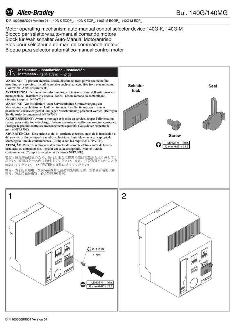
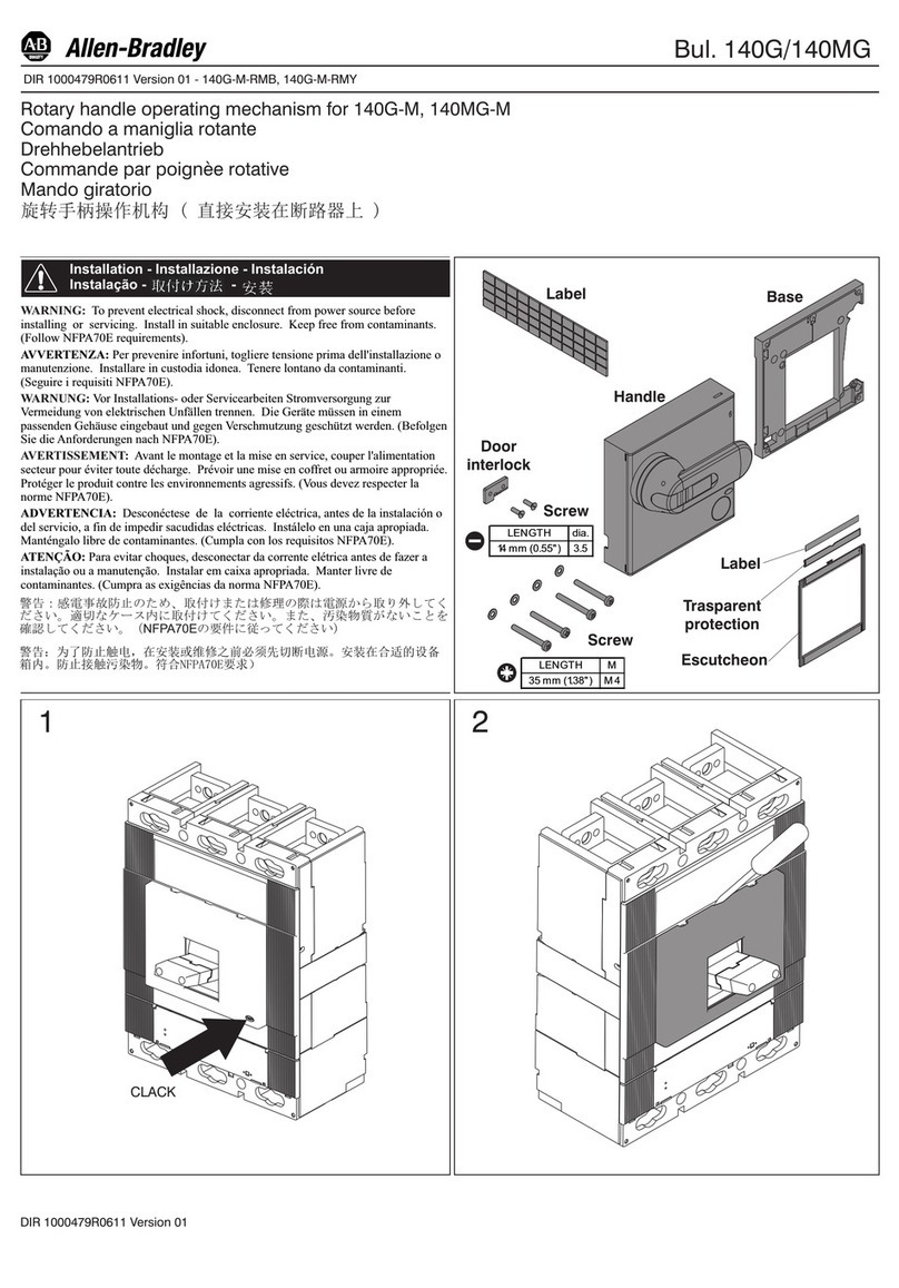
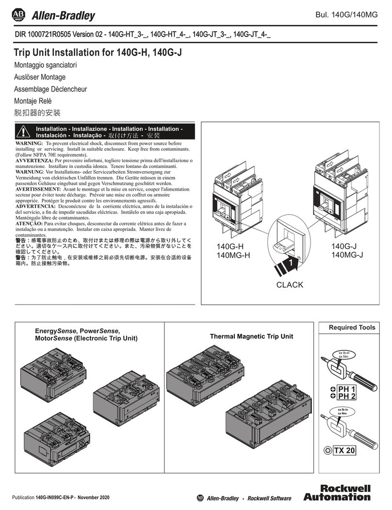
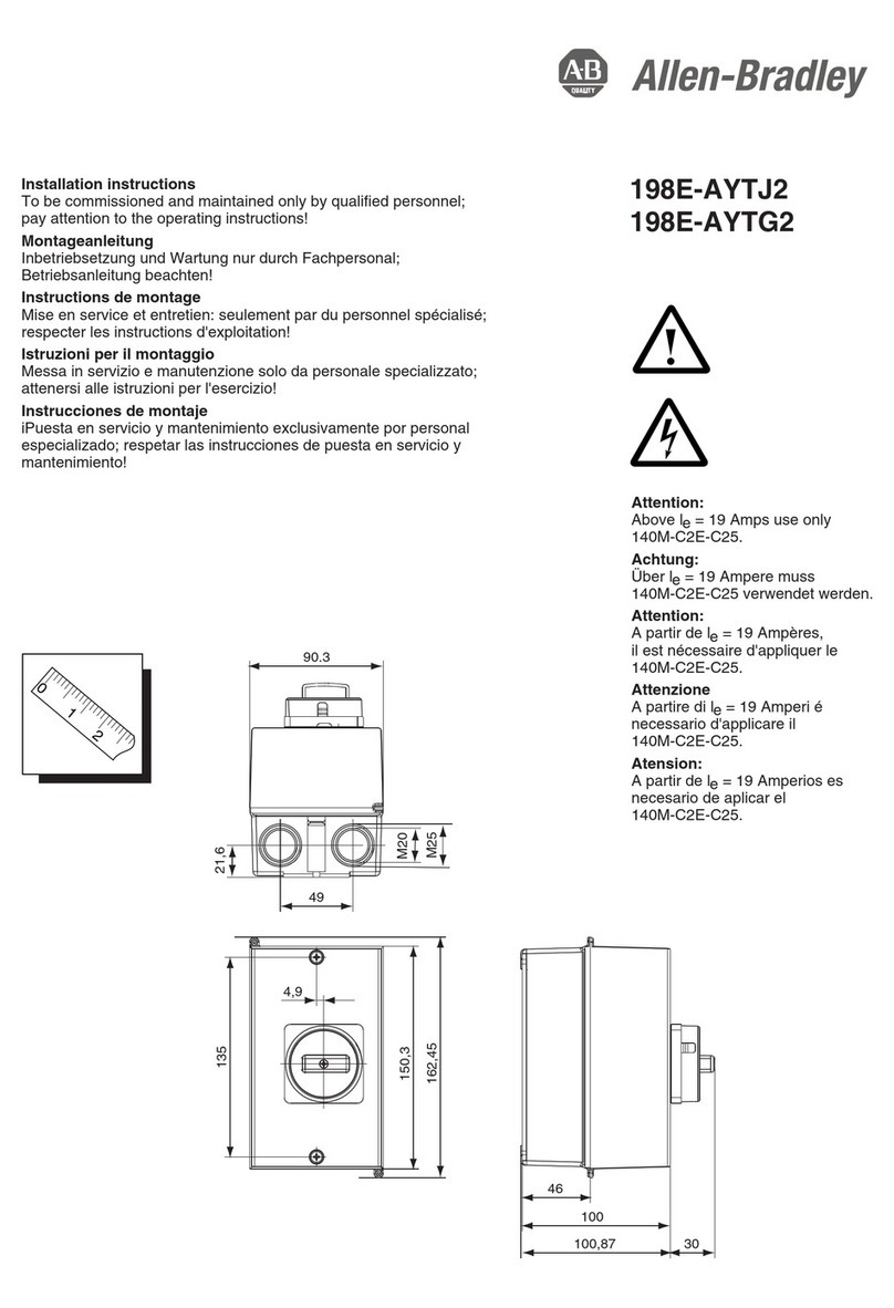
  9. Allen-Bradley 800G Series User manual

Allen-Bradley 800G Series User manual

Installation Instructions
Original Instructions
Bulletin 800G Assembled Stations
Catalog Numbers
800G-1
x
-EX, 800G-2x-EX, 800G-3x-EX
Product Description
There are many variations and configurations available for assembled
station solutions. All assembled station configurations use a one-hole
(800G-1x-EX), two-hole (800G-2x-EX), or three-hole (800G-3x-EX)
enclosure with various front-of-panel operators and back-of-panel
components.
Up to three enclosures of any size can be ganged together in a vertical
arrangement, allowing a combined assembled station to have up to nine
operators (three enclosures with each enclosure containing three
operators). Assembled stations have various conduit-entry
configurations using plastic or metal cable glands, along with many
different accessories such as locking covers, locking guards, and custom
legend plates. Assembled stations must be ordered directly from
Rockwell Automation to maintain compliance with hazardous
location standards and certifications; field assembly is not permitted.
Safety Instructions
Improper installation can cause malfunctioning and the loss of
explosion protection.
All assembled stations can only be used within the specified ambient
temperature range (depending on the voltage, current, and hazardous
area classification).
ATTENTION: To help prevent electrical shock, disconnect from
power source before installing or servicing. Follow NFPA 70E
requirements. Install in suitable enclosure. Keep free from
contaminants.
Only suitably trained personnel can install, adjust, commission,
use, assemble, disassemble, and maintain the product in
accordance with applicable code of practice. If a malfunction or
damage occurs, do not attempt to repair the product.
IMPORTANT When working in hazardous areas, thesafety of personnel
and equipment depends on compliance with the relevant
safety regulations. The people in charge of installation and
maintenance bear a special responsibility. They must be
knowledgeable of the applicable rules andregulations.
These instructions provide a summary of the most important
installation measures. Everyone working with the product
mustreadtheseinstructionsso that theyarefamiliarwiththe
correct handling of the product.
Keep these instructions for future reference as they must be
available throughout the expected life of the product.
Assembled Stations
Certifications
ATEX CML 15 ATEX 3024
IECEx IECEx CML 15.0014
NEPSI GYJ17.1200X
INMETRO UL-BR 17.0366
Gas Protection Type II 2 G Ex db eb IIC T6 Gb
Dust Protection Type II 2 D Ex tb IIIC T80°C Db
Mechanical and Electrical Ratings
Zone Rating Zone 1, Zone 2, Zone 21, Zone 22
Ambient Temperature Range -55…+60 °C (-67…+140 °F)
Degree of Protection IP64/IP66
Enclosure Material Thermoplastic
Enclosure Sizes One-hole, two-hole, or three-hole
Ganged Enclosures Up to three enclosures
Cable Gland Clamping Range
Plastic M20/Plastic M20x2 Cable Ø7…13 mm (9/32…33/64 in.)
Plastic M25 Cable Ø12…17 mm (15/32…43/64 in.)
Metal M20 Cable Ø8.5…14.5 mm (21/64… 37/64 in.)
Metal M25 Cable Ø12…20 mm (15/32…25/32 in.)
Metal M20x2 Cable Ø6…12 mm (15/64…15/32 in.)
Metal Cable Gland Armor™ WireSize
Metal M20 Armor wire Ø0.8…1.3 mm (1/32…3/64 in.)
Metal M25 Armor wire Ø1.0…1.6 mm (3/64…1/16 in.)
Metal M20 x 2 Armor wire Ø0.7…1.2 mm (1/32…3/64 in.)
Contact Block Components
Rated Insulation Voltage, Max 690V AC
Rated Voltage (Ue) AC 250V and 400V; DC 24V and 110V
Utilization Category (AC) AC-12: 16 A, 400V, AC-15: 10 A, 400V
Utilization Category (DC) DC-13: 1 A, 24V, DC-13: 0.5 A, 110V
Conventional Thermal Current (Ithe)16 A / 40 °C (104 °F)
11 A / 60 °C (140 °F)
Contact Options 1 N.O./1 N.C., 2 N.O., 2 N.C.
Wire/Cable Size 0.75…2.5 mm² (18…14 AWG)
Power Module Components
Rated Insulation Voltage 300V
Power Consumption ≤ 1 W
Rated Voltage (Ue) Ta< 50 °C (122 °F) 12…250V AC, 12…60V DC
Rated Voltage (Ue) Ta< 60 °C (140 °F) 12…24V AC/DC
Wire/Cable Size 0.75…2.5 mm² (18…14 AWG)
Power Module with Contact Block Components
Rated Insulation Voltage 300V
Power Consumption ≤1 W
Rated Voltage (Ue) Ta< 50 °C (122 °F) 12…250V AC, 12…60V DC
Rated Voltage (Ue) Ta< 60 °C (140 °F) 12…24V AC/DC
Contact Options 1 N.O., 1 N.C.
Utilization Category (AC) AC-15: 1 A, 230V
Utilization Category (DC) DC-13: 0.25 A, 24V
Wire/Cable Size 0.75…2.5 mm² (18…14 AWG)
Assembled Stations
2Rockwell Automation Publication 800G-IN005A-EN-P - May 2018
Bulletin 800G Assembled Stations
Use in areas other than those areas specified or the modification of the
product by anyone other than the manufacturer is not permitted and
exempts Rockwell Automation from liability for defects and any
further liability.
The applicable statutory rules and other binding directives that relate
to workplace safety, accident prevention, and environmental
protection must be observed.
Before you commission or restart operation, check compliance with all
applicable laws and directives.
All enclosures, front-of-panel operators, and back-of-panel modules
can be used only if they are in a clean, undamaged condition. Do not
modify these components in any way.
Standards Conformed To
Assemble, Install, and Commission
• Only qualified personnel are allowed to assemble, disassemble,
install, and commission the device.
• Protect devices against mechanical damage or electrostatic
discharge.
• Use suitable tools for installation. Do not modify the
assembled station or components in any way.
• Use cable that is rated with an appropriate temperature range
suitable for the application.
• IEC/EN 60079-17 must be observed.
Installation and Removal
Protective Earthing Components
For metal cable glands, follow these steps:
1. Position the earth plate
where the metal cable
gland is installed (top
or bottom).
2. Install the earth plate
between the rib and
inside wall of the
enclosure.
3. Open the terminal cages of the earth plate and insert the
conductors.
4. Tighten the earth plate terminals to a torque range of
0.7…1.0 N·m (6…9 lb·in).
For plastic cable glands, follow these steps:
\
1. Position the earth
bracket where the
plastic cable gland is
installed (top or
bottom).
2. Install the earth
bracket between the
rib and inside wall of
the enclosure.
3. Open the terminal cages of the earth bracket and insert the
conductors.
4. Tighten the earth bracket terminals to a torque range of
0.7…1.0 N·m (6…9 lb·in).
Contact Blocksand PowerModules
To install contact blocks and power modules, follow these steps:
1. Align the notch of the component with the cut-out in the
enclosure rail.
2. Snap the contact block or power module onto the rail of the
enclosure.
3. Check that the component is secured to the enclosure rail.
To remove contact blocks and power modules, follow these steps:
1. Position a screwdriver inside of the black tab at the base of the
component.
2. Gently pull the black tab in a direction away from the
enclosure rail.
3. Lift up on the component to remove it from the enclosure rail.
WiringContact Blocks and PowerModules
Take care when following these steps to connect cable to contact blocks
or power modules:
1. Strip 40 mm
(1.575 in.) of
sheath off the
cable.
2. Remove
approximately
6mm(.236 in.)
of insulation
from the
conductors.
3. Prepare the ends of the fine-stranded and multi-stranded
conductors. Crimp wire end sleeves with a suitable crimp tool.
Suitable connection cross-sections are 0.75…2.5 mm
(18…14 AWG).
4. Open terminal cage and insert conductors.
5. Tighten the terminals to a torque range of 0.4…0.7 N·m
(3.5…6.2 lb·in).
• EN 60079-0 • EN 60079-1 • EN 60079-7 • EN 60079-31
• IEC 60079-0 • IEC 60079-1 • IEC 60079-7 • IEC 60079-31
ATTENTION: Risk of serious injury due to incorrect assembly,
installation, and commissioning.
IMPORTANT The assembled stations that are pictured serve as an example
for all assembled station configurations.
IMPORTANT An earth plate must be used for grounding enclosures with a
metal cable gland.
0.7…1.0 N·m
(6…9 lb·in)
Earth Plate
(800G-AEPx)
IMPORTANT An earth bracket must be used for grounding enclosures with
a plastic cable gland.
0.7…1.0 N·m
(6…9 lb·in)
Earth Bracket
(800G-AEB)
0.75…2.5 mm²
(18…14 AWG)
Contact Block/Power Module
(800G-XB
x
-EX, 800G-DB
x
-EX,
and 800G-DB
x
X
x
-EX)
0.4…0.7 N·m
(4…6 lb·in)
Rockwell Automation Publication 800G-IN005A-EN-P - May 2018 3
Bulletin 800G Assembled Stations
Operators
To install operators, follow these steps:
1. Align the
four tabs on
the operator
with the
notches
inside of the
enclosure
cover.
2. Secure the operator by twisting the mounting ring wrench in a
clockwise direction.
3. Tighten the mounting ring nut to a torque range of
2.8…3.4 N·m (25…30 lb·in).
4. If installing a replacement operator, verify that the operator
plunger aligns with the contact block pins.
To remove operators, follow these steps:
1. Loosen the mounting ring by twisting the wrench in a
counterclockwise direction.
2. Remove the operator and install an equivalent replacement
operator (same part number).
Enclosure
1. Install the optional enclosure identification label in the recess
of the enclosure cover.
2. Reference the mounting hole pattern that is given in Enclosure
Mounting on page 4.
3. Tighten the hardware to enclosure base.
4. All open cable entry holes must be sealed with a certified
stopping plug.
5. Tighten the enclosure cover screws to a torque range of
0.8…1.0 N·m (7…9 lb·in).
Commissioning
Before commissioning, check the following:
• The assembled station has been installed in compliance with
the regulations.
• The assembled station is not damaged (free of cracks or
physical damage) and is clean.
• The connection has been established properly and verify that
the conductors are secure.
• The minimum ingress protection levels have been met for the
hazardous location environment (gas explosion IP64, dust
explosion IP6X).
Maintenance
• Only qualified personnel are allowed to do any maintenance
and fault clearance.
• IEC/EN 60079-17 must be observed.
You must keep all assembled station components in good condition,
operate them properly, monitor them, and clean them regularly.
• Check all operators, modules, contact blocks, seals, glands, and
cables regularly for cracks, damage, and physical defects. Verify
that they are properly installed.
Repair and Replacement
• Operators are defective if they no longer actuate the attached
back-of-panel components, if the lens is damaged on
illuminated operators, or if the integrity of the device and/or
sealing has been compromised.
• Back-of-panel devices are defective if the contact block does
not function properly or the indicator does not illuminate on
the power module.
• The enclosure is defective if the gasket or enclosure body have
cracks, damage, or physical defects.
• Devices must be replaced with an equivalent catalog number
from the manufacturer.
Accessories and Replacement Parts
For more accessories and replacement parts that Rockwell Automation
offers, see https://ab.rockwellautomation.com/Push-Buttons/
Hazardous-Location/800G.
Disposal
At the end of its life, this equipment must be collected separately from
any unsorted municipal waste. Follow all local and national
requirements for disposal of this product.
Mounting Ring
Wrench (800G-AW1)
2.8…3.4 N·m (25…30 lb·in)
Mounting Nut
(800G-AMN1)
Enclosure
Identification
Label
(800G-AEL)
0.8…1.0 N·m
(7…9 lb·in)
ATTENTION: Risk of serious injury due to incorrect maintenance.
IMPORTANT • You can clean operators with compressed air.
• Do not clean contact blocks or power modules with
compressed air.
• Enclosures can becleaned with a wet cloth; enclosures are
limited to wet cleaning!
ATTENTION: Defective operators, contact blocks, power modules,
accessories, and enclosures cannot be repaired; they must be
replaced.
Allen-Bradley, Armor, Rockwell Automation, and Rockwell Software are trademarks of Rockwell Automation, Inc.
Trademarks not belonging to Rockwell Automation are property of their respective companies.
Rockwell Otomasyon Ticaret A.Ş., Kar Plaza İş Merkezi E BlokKat:6 34752 İçerenköy, İstanbul, Tel: +90 (216) 5698400
Rockwell Automation maintains current product environmental information on its website at
http://www.rockwellautomation.com/rockwellautomation/about-us/sustainability-ethics/product-environmental-compliance.page.
EEE Yönetmeligine Uygundur.
Publication 800G-IN005A-EN-P - May 2018 10001535808 Ver 00
Copyright © 2018 Rockwell Automation, Inc. All rights reserved. Printed in the U.S.A.
Approximate Dimensions
Dimensions are shown in millimeters (inches).
Enclosure Mounting
Declaration of Conformity
Rockwell Automation, Inc. declares that the 800G-1x-EX,
800G2xEX, and 800G-3x-EX Series A Assembled Stations are in
compliance with Essential Health and Safety Requirements of
Directive 2014/34/EU (ATEX) as follows:
• Equipment Group II, Equipment Category 2
• Type of Protection “Ex db eb IIC Gb / Ex tb IIIC T80°C Db”
• Compliance to standards EN 60079-0:2012+A11:2013,
EN 60079-1:2014, EN 60079-7: 2015, and
EN 6007931: 2014 per ATEX Type Examination Certificates
CML 15ATEX3024
The full text of the EU declaration of conformity is available at the
following website:
http://www.rockwellautomation.com/global/certification
88.5
(3.48)
133.0
(5.24)
3.0
(0.12)
81.0
(3.19)
88.5
(3.48)
81.0
(3.19)
91.0
(3.58)
3.0
(0.12)
Catalog Number
800G-1x-EX
Catalog Number
800G-2x-EX
88.5
(3.48)
179.0
(7.05)
3.0
(0.12)
81.0
(3.19)
Catalog Number
800G-3x-EX
Cat. No. Hole Ø [mm (in.)] X - Width [mm (in.)] Y - Height [mm (in.)]
800G-1x-EX
5.5 (7/32) 73 (2-7/8)
50 (1-31/32)
800G-2x-EX 93 (3-21/32)
800G-3x-EX 136 (5-23/64)
Y
X
Y
X
Y
X
Catalog Number
800G-1x-EX
Catalog Number
800G-2x-EX
Catalog Number
800G-3x-EX

This manual suits for next models

3

Other Allen-Bradley Industrial Equipment manuals

Allen-Bradley 1492-P User manual

Allen-Bradley

Allen-Bradley 1492-P User manual

Allen-Bradley PowerFlex 7000 Series User manual

Allen-Bradley

Allen-Bradley PowerFlex 7000 Series User manual

Allen-Bradley PowerFlex 755T User manual

Allen-Bradley

Allen-Bradley PowerFlex 755T User manual

Allen-Bradley 140G-M-EXT3 User manual

Allen-Bradley

Allen-Bradley 140G-M-EXT3 User manual

Allen-Bradley Guardmaster LRTS User manual

Allen-Bradley

Allen-Bradley Guardmaster LRTS User manual

Allen-Bradley 140G EXT3 Series User manual

Allen-Bradley

Allen-Bradley 140G EXT3 Series User manual

Allen-Bradley 100L-C20 User manual

Allen-Bradley

Allen-Bradley 100L-C20 User manual

Allen-Bradley 140G-G User manual

Allen-Bradley

Allen-Bradley 140G-G User manual

Allen-Bradley 140-KN User manual

Allen-Bradley

Allen-Bradley 140-KN User manual

Allen-Bradley 1747-DSN User manual

Allen-Bradley

Allen-Bradley 1747-DSN User manual

Allen-Bradley 140G EXS3 Series User manual

Allen-Bradley

Allen-Bradley 140G EXS3 Series User manual

Allen-Bradley Powermonitor 3000 User manual

Allen-Bradley

Allen-Bradley Powermonitor 3000 User manual

Allen-Bradley 140G-N-RMB User manual

Allen-Bradley

Allen-Bradley 140G-N-RMB User manual

Allen-Bradley 140G-M User manual

Allen-Bradley

Allen-Bradley 140G-M User manual

Allen-Bradley 140G Series User manual

Allen-Bradley

Allen-Bradley 140G Series User manual

Allen-Bradley 140G-N-TC3H User manual

Allen-Bradley

Allen-Bradley 140G-N-TC3H User manual

Allen-Bradley 140G-H Installation and operation manual

Allen-Bradley

Allen-Bradley 140G-H Installation and operation manual

Allen-Bradley 140G-N-TLH3 User manual

Allen-Bradley

Allen-Bradley 140G-N-TLH3 User manual

Allen-Bradley 198E-AYTJ2 User manual

Allen-Bradley

Allen-Bradley 198E-AYTJ2 User manual

Allen-Bradley 140G-R-TLV3 User manual

Allen-Bradley

Allen-Bradley 140G-R-TLV3 User manual

Allen-Bradley 194R-NU100-1753 User manual

Allen-Bradley

Allen-Bradley 194R-NU100-1753 User manual

Allen-Bradley Bulletin 2364F User manual

Allen-Bradley

Allen-Bradley Bulletin 2364F User manual

Allen-Bradley 9300-VSELV User manual

Allen-Bradley

Allen-Bradley 9300-VSELV User manual

Allen-Bradley ControlNet Coax Tap 1786-TPR User manual

Allen-Bradley

Allen-Bradley ControlNet Coax Tap 1786-TPR User manual

Popular Industrial Equipment manuals by other brands

LEGRAND Solarfective SF-T4 installation instructions

LEGRAND

LEGRAND Solarfective SF-T4 installation instructions

Jäger S33-M110.01 S26 manual

Jäger

Jäger S33-M110.01 S26 manual

Festo VTEM Translation of the original instructions

Festo

Festo VTEM Translation of the original instructions

MFJ 263 instruction manual

MFJ

MFJ 263 instruction manual

Pulsar AWO317 Assembly instructions

Pulsar

Pulsar AWO317 Assembly instructions

ABB Power2 800-M Assembly instructions

ABB

ABB Power2 800-M Assembly instructions

Traub TNL12.2 operating instructions

Traub

Traub TNL12.2 operating instructions

Siemens 3SU1400-1LL10-.BA1 Original operating instructions

Siemens

Siemens 3SU1400-1LL10-.BA1 Original operating instructions

Hubbell KILLARK UGFI 2P Series INSTALLATION, OPERATION & MAINTENANCE DATA SHEET

Hubbell

Hubbell KILLARK UGFI 2P Series INSTALLATION, OPERATION & MAINTENANCE DATA SHEET

Siemens SIMATIC ET 200SP HA Equipment manual

Siemens

Siemens SIMATIC ET 200SP HA Equipment manual

Aircycle Bulb Eater VRS Premium manual

Aircycle

Aircycle Bulb Eater VRS Premium manual

Siemens SIMATIC operating instructions

Siemens

Siemens SIMATIC operating instructions

Shini SG-23 Series manual

Shini

Shini SG-23 Series manual

STAMPLINE S-120 operating manual

STAMPLINE

STAMPLINE S-120 operating manual

Cameron CLIF MOCK CMC-250 user manual

Cameron

Cameron CLIF MOCK CMC-250 user manual

Schmalz SB FU Series operating instructions

Schmalz

Schmalz SB FU Series operating instructions

KINGZO GMA120-S-A1 manual

KINGZO

KINGZO GMA120-S-A1 manual

ABB XAC23983 Operation manual

ABB

ABB XAC23983 Operation manual

manuals.online logo
manuals.online logoBrands
  • About & Mission
  • Contact us
  • Privacy Policy
  • Terms and Conditions

Copyright 2025 Manuals.Online. All Rights Reserved.