manuals.online logo
Brands
  1. Home
  2. •
  3. Brands
  4. •
  5. Allied Telesis
  6. •
  7. Wireless Access Point
  8. •
  9. Allied Telesis AT-WA7500 User guide

Allied Telesis AT-WA7500 User guide

Antenna and Cable
Application Guide for the
AT-WA7500 and
AT-WL2411 Access Points
______________________________________________________________________________________
PN 613-50537-00 Rev A 1
______________________________________________________________________________________
PN 613-50537-00 Rev A 2
Table of Contents
Introduction 4
Regulatory Concerns 4
Basic Antenna Concepts 6
Radiation Patterns of Various Antennas 6
Typical Installations
Direct Connection Antenna Circuits 7
Direct Connection Antenna Connection 7
Antenna Circuits with Splitter 7
Antenna Circuits with Splitter and Lightning Suppressors 9
Plenum Cable Cross Reference 10
Cable Assemblies
AT-INT067265-00 - TNC Plug / N Receptacle, 12 inch 11
AT-INT67266-00 - TNC Plug / N Plug, 24 inch 12
AT-INT071178-00 - TNC Plug / N Plug, 12 feet 12
AT-INT072822-00 - TNC Plug/ N Plug, 24 inch 12
AT-INT072823-00 - TNC Plug/ N Plug, 12 feet 12
AT-INT064616-00 - N Plug / N Plug, 30 inch 13
AT-INT063245-00 - N Plug / N Plug, 60 inch 13
AT-INT063246-00 - N Plug / N Plug, 20 feet 13
AT-INT71179-00 - N Plug / N Plug, 30 feet 13
AT-INT072824-00 - N Plug / N Plug, 30 inch 13
AT-INT072825-00 - N Plug / N Plug, 5 feet 13
AT-INT072826-00 - N Plug / N Plug, 20 feet 13
AT-INT072827-00 - N Plug / N Plug, 30 feet 13
AT-INT069886-00 - MMCX / N Receptacle 14
AT-INT069887-00 - Radiall (Lucent) / N Receptacle 15
AT-INT070402-00 - MMCX / N Plug 16
AT-INT070403-00 - Radiall (Lucent) / N Plug 17
Antennas
2.4 GHz 18-33
2.4 GHz Antennas
AT-INT63363-00 - Antenna, 2.4 GHz, Omni 18
AT-INT063365-00 - Antenna, 2.4 GHz, Yagi 19
AT-INT63366-00 - Antenna, 2.4 GHz, Flat Panel 20
AT-INT065349-00 - Antenna, 2.4 GHz, 9DBI, Omni 21
AT-INT066147-00 - Antenna, TNC, 2.4 GHz, Dipole 22
AT-INT067261-00 - Antenna, 2.4 GHz, 3DBI, Mini Omni
(N Recept Conn) 23, 24
AT-INT070140-00 - Antenna, 2.4 GHz, 3DBI,
Mini Omni (MMCX Conn) 23, 25
AT-INT070141-00 - Antenna, 2.4 GHz, 3DBI,
Mini Omni, (Radiall Conn) 23, 26
AT-INT067262-00 - Antenna, 2.4 GHz, 5DBI, Dual Flat Panel 27
______________________________________________________________________________________
PN 613-50537-00 Rev A 3
Table of Contents (cont.)
AT-INT067263-00 - Antenna, 2.4 GHz, 9DBI, Flat Panel 28
AT-INT067263-00 - Rear View 29
AT-INT71121-00 - Antenna, 2.4 GHz, Diversity, 3DBI 31
AT-INT71122-00 - Antenna, 2.4 GHz, Corner Reflect 32
AT-INT71488-00 - Diversity Antenna, 2.4 GHz (MMCX Conn) 33
AT-INT71489-00 - Diversity Antenna, 2.4 GHz (Radiall Conn) 33
N Receptacle used on various antennas 25
5.25 – 5.35 GHz (Mid-Band) 34-38
AT-INT072730-00 - Antenna, 5.25 – 5.35 GHz, Omni,
Swivel TNC, 4 DBI 34
AT-INT072759-00 - Antenna, 5.25 – 5.35 GHz, Omni, 6 DBI 35
AT-INT072760-00 - Antenna, 5.25 – 5.35 GHz, Omni, 9 DBI 36
AT-INT072761-00 - Antenna, 5.25 – 5.35 GHz, Omni, 3 DBI,
Ceiling Mount 37
AT-INT072762-00 - Antenna, 5.25 – 5.35 GHz, Corner Reflect 38
Accessories
AT-INT069888-00 - Kit, Bracket, Mounting, Antenna 39
AT-INT069893-00 - Kit, Power Supply Holder 40
AT-INT061868-00 - Lightning Suppressor 40
______________________________________________________________________________________
PN 613-50537-00 Rev A 4
Introduction
The purpose of this document is to provide Allied Telesyn, Inc. personnel a tool which will enable them to
better understand how the various Allied Telesyn antennas, cable assemblies, and accessories blend
together.
Regulatory Concerns
Note: The information below will help you to understand some of the regulatory issues surrounding the
use of antenna, antenna circuits, and radios. However, it is critical to remember that all antennas must be
approved and certified before they can be used with radio (RF) equipment purchased from Allied Telesyn.
FCC
FCC requirements limit the total output power of a wireless LAN system operating in 2.4 GHz frequency
ranges to 4 Watts. This limit is expressed in EIRP, which stand for “Effective Isotropically Radiated
Power.” This is the total power created by the transmitter and gain generated by the antenna, minus any
loss due to cabling and connections. Given this 4W (4000 mW) maximum, the EIRP must not exceed
36dBi.
ETSI
ETSI requirements limit the total output power of a 2.4 GHz wireless LAN system to 0.1 Watt (100 mW).
Given this 100 mW maximum, the EIRP must not exceed 20dBm. Most European countries such as France
and Italy operate under a lower power directive, which limits them to a maximum output limit of 10 mW.
Non-ETSI & Non-FCC Countries
Electromagnetic-transmission regulations are mandated by each country’s own governing body. Many
countries follow the directives issued by ETSI or the FCC but others create their own regulations.
Before adding radios or antennas to a RF system, please consult a certified Allied
Telesyn Systems Consultant operating in the country where the system will be used.
______________________________________________________________________________________
PN 613-50537-00 Rev A 5
Basic Antenna Concepts
Antennas and Power
Antennas do not increase nor decrease the power applied to them. They can only transmit or receive the
amount of power that is applied to them. It is possible to have some power loss before or after the signal
leaves the antenna. An example of this is “line loss: which is a decrease in power due to imperfect
connections and imperfect conductivity to cabling materials. It is, however, possible to increase the power
output in a certain direction. But the total power emitted will always be the same as the amount applied to
the antenna minus the amount lost due to line loss, ohmic loss, reflection loss etc…
dBi – (decibels relative to an isotropic {spherical} radiation pattern)
An isotropic antenna is a theoretical antenna that radiates in the shape of a perfect sphere.
dBm – (decibels relative to one milliwatt)
dBm is a commonly used unit of measurement in the RF industry that expresses radio frequency power
relative to a 1 mW point of reference.
dBd – (decibels relative to a ½ wave dipole antenna)
dBd is gain with respect to a ½ wave dipole antenna. Some commercial antenna companies use dBd to rate
their antennas.
EIRP – (Effective isotropically radiated power)
The mathematical product of (1) the power supplied to the antenna and (2) its gain.
Gain
Gain is given in dB (decibels). If an “I” is added as in 3dBi, this rating is relative to an “isotropic” antenna.
An isotropic antenna is a theoretical antenna that radiates in the shape of a perfect sphere. If a “d” is added
as in 3dBd, this rating is relative to a “dipole” antenna. A dipole antenna with a rating of 2.14dB is
equivalent to a 0dBd antenna.
Line-of-sight
This refers to the fact that some electromagnetic wave frequencies require a clear line of sight between
transmitter and receiver. This is largely because higher frequency electromagnetic waves, such as those in
the 2.4 GHz range, do not bend around or penetrate objects as well as some lower frequency signals.
Multipath, Reflection, or Physical Interference
Because of the electromagnetic properties of waves used to transmit data, large metal objects in the
immediate transmission path of the antenna will likely cause distortion of the signal and should therefore be
avoided.
Omnidirectional
An omnidirectional antenna radiates evenly horizontally around the antenna in a plane parallel to the earth.
These antennas do not always radiate evenly vertically around the antenna in a plane perpendicular to the
earth. By giving up vertical coverage, above and or below the antenna and refocusing that signal around
the antenna, it is possible to achieve gain with an omnidirectional antenna.
Omni-gain
Wavelength and operating frequency determine the size of the antenna. By using a longer antenna, you do
not achieve greater overall coverage, but you can achieve greater distance in a focused direction. For
example, omnidirectional antennas with gain achieve some measure of gain in the horizontal plane.
R
adiation Patters of Various Antennas
O
mnidirectional:
C
ircular patter in open spaces
R
ange is slightly effected by antenna gain but the radiation pattern will
r
emain relatively circular.
F
lat Panel:
M
odest directional coverage with a slight backlobe
T
he main lobe of the radiation pattern can be from almost circular to fairly
o
blong in shape. Good for slightly directional coverage such as down
c
orridor or away from walls.
D
ual Flat Panel:
B
i-directional coverage
G
ood for transmission down two opposing directions of a corridor.
D
irectionalYAGI (High Gain):
H
ighly focused signal.
G
ood for wireless bridging or very specialized coverage.
T
here must always be a tradeoff between gain and coverage area. As can be
s
een in the radiation patterns presented, the higher the gain (directional
d
istance) as with theYagi antenna, the narrower the coverage.And
c
onversely, the lower the gain, the more universal the coverage about the
a
ntenna's axis.
Antenna patterns are 3
dimensional. The radiation
patterns (above) are views
of the azimuth plain, which
is a top down view.
______________________________________________________________________________________
PN 613-50537-00 Rev A 6
WA7500
Direct ConnectionAntenna Circuit
AnyAlliedTelesyn 2.4 GHz, or 5.3 GHz (Mid-Band)
Antenna with N Receptacle Connector
WA7500
067266 - Cable - 2' (61cm) -- New Part #:AT-INT67266-00
071178 - Cable - 12" (366cm) -- New Part #: AT-INT71178-00
*See Table on page 12 for plenum cable cross reference.
2
.4 GHz and 5.3 GHz (Mid-Band).
WL2411
Connection Antenna Circuit
WL2411
Any AlliedTelesyn 2.4 GHz Antenna
with N Receptacle Connector
070402 - Cable - MMCX -- New Part #: AT-INT70402-00
070403 - Cable - Radiall -- New Part #: AT-INT70403-00
069888 - Kit, Bracket, Mtg -- New Part #:AT-INT6988-00
070140 - Antenna, 3dBi Mini Omni, MMCX -- New Part #:AT-INT70140-00
070141 - Antenna, 3dBi Mini Omni, Radiall (Lucent) -- New Part #:AT-INT70141-
00
071488 - Diversity Antenna, MMCX -- New Part #:AT-INT71488-00
071489 - Diversity Antenna, Radiall (Lucent) -- New Part #:AT-INT71489-00
______________________________________________________________________________________
PN 613-50537-00 Rev A 7
WA7500
Direct Circuit with Splitter
Any AlliedTelesyn 2.4 GHz, or 5.3 GHz (Mid-Band)
Antenna with N Receptacle Connector
WA7500
WA7500 Support
2.4 GHz and 5.3GHz (Mid-Band).
Splitter
AT-INT63198-00 - Splitter, 2.4 GHz
AT-INT67265-00 - Adapter cable
1' (30cm)
AT-INT064616-00 - Cable - 2.5' (76cm)
AT-INT063245-00 - Cable - 5' (152cm)
AT-INT063246-00 - Cable - 20' (610cm)
AT-INT71179-00 - Cable - 30' (914cm)
AT-INT064616-00 - Cable - 2.5' (76cm)
AT-INT063245-00 - Cable - 5' (152cm)
AT-INT063246-00 - Cable - 20' (610cm)
AT-INT71179-00 - Cable - 30' (914cm)
* See Table on page 12 for plenum cable cross reference
WL2411 2.4 GHz Antenna
Circuit with Splitter
WL2411
Any AlliedTelesyn 2.4 GHz Antenna
with N Receptacle Connector
Splitter
AT-INT064616-00 - Cable - 2.5' (76cm)
AT-INT063245-00 - Cable - 5' (152cm)
AT-INT063246-00 - Cable - 20' (610cm)
AT-INT71179-00 - Cable - 30' (914cm)
AT-INT064616-00 - Cable - 2.5' (76cm)
AT-INT063245-00 - Cable - 5' (152cm)
AT-INT063246-00 - Cable - 20' (610cm)
AT-INT71179-00 - Cable - 30' (914cm)
AT-INT63198-00 - Splitter, 2.4 GHz
AT-INT069886-00 - Cable - MMCX
AT-INT069887-00 - Cable - Radiall
AT-INT069888-00 - Kit, Bracket, Mtg
______________________________________________________________________________________
PN 613-50537-00 Rev A 8
______________________________________________________________________________________
PN 613-50537-00 Rev A 9
WA7500
2.4 GHz / 5.3 GHz (Mid-Band)
Antenna Circuit with Splitter and Lightning Arrestor
Any AlliedTelesyn 2.4 GHz, or 5.3 GHz (Mid-Band)
Antenna with N Receptacle Connector
WA7500
WA7500 Support
2.4 GHz and 5.3 GHz (Mid-Band).
Splitter
AT-INT63198-00 - Splitter, 2.4 GHz
AT-INT67265-00 - Adapter cable
1' (30cm)
AT-INT064616-00 - Cable - 2.5' (76cm)
AT-INT063245-00 - Cable - 5' (152cm)
AT-INT063246-00 - Cable - 20' (610cm)
AT-INT71179-00 - Cable - 30' (914cm)
AT-INT064616-00 - Cable - 2.5' (76cm)
AT-INT063245-00 - Cable - 5' (152cm)
AT-INT063246-00 - Cable - 20' (610cm)
AT-INT71179-00 - Cable - 30' (914cm)
AT-INT064616-00 - Cable - 2.5' (76cm)
AT-INT063245-00 - Cable - 5' (152cm)
AT-INT063246-00 - Cable - 20' (610cm)
AT-INT71179-00 - Cable - 30' (914cm)
AT-INT61868-00 - Lightning Suppressor
AT-INT58661-00 - Capsule
* See Table on page 12 for plenum cable cross reference
2101 / 2102 2.4 GHz Antenna Circuit
with Splitter and Lightning Suppressor
WL2411
Any AlliedTelesyn 2.4 GHz Antenna
with N Receptacle Connector
Splitter
AT-INT064616-00 - Cable - 2.5' (76cm)
AT-INT063245-00 - Cable - 5' (152cm)
AT-INT063246-00 - Cable - 20' (610cm)
AT-INT71179-00 - Cable - 30' (914cm)
AT-INT064616-00 - Cable - 2.5' (76cm)
AT-INT063245-00 - Cable - 5' (152cm)
AT-INT063246-00 - Cable - 20' (610cm)
AT-INT71179-00 - Cable - 30' (914cm)
AT-INT63198-00 - Splitter, 2.4 GHz
AT-INT069886-00 - Cable - MMCX
AT-INT069887-00 - Cable - Radiall
AT-INT069888-00 - Kit, Bracket, Mtg
AT-INT61868-00 - Lightning Suppressor
AT-INT58661-00 - Capsule
AT-INT064616-00 - Cable - 2.5' (76cm)
AT-INT063245-00 - Cable - 5' (152cm)
AT-INT063246-00 - Cable - 20' (610cm)
AT-INT71179-00 - Cable - 30' (914cm)
______________________________________________________________________________________
PN 613-50537-00 Rev A 10
Plenum Cable Cross Reference
Description Plenum Cable Assembly Part
Number Cable Assembly
Length
TNC Plug / N
Receptacle AT-INT072821-00 12 Inches
TNC Plug / N Plug AT-INT072822-00 24 Inches
TNC Plug / N Plug AT-INT072823-00 12 Feet
N Plug / N Plug AT-INT072824-00 30 Inches
N Plug / N Plug AT-INT072825-00 5 Feet
N Plug / N Plug AT-INT072826-00 20 Feet
N Plug / N Plug AT-INT072827-00 30 Feet
* Recommended cable assembly for plenum applications
AT-INT067265-00
Cable Assy, TNC Plug / N Receptacle
12 Inch
Used to connect AT-WA7500 to N Plug Cable Assys:
AT-INT064616-00, AT-INT063245-00, AT-INT063246-00,
AT-INT71179-00, AT-INT072824-00, AT-INT072825-00,
AT-INT072826-00, and AT-INT072827-00.
Cable loss standard (AT-INT067265-00): .2 DB at 2.4 GHz
.3DBat5.35GHz
Cable loss plenum (AT-INT072821-00): .2 DB at 2.4 GHz
.3DBat5.35GHz
______________________________________________________________________________________
PN 613-50537-00 Rev A 11
Cable Assy, TNC Plug / N Plug
AT-INT67266-00 – 24 Inch standard
AT-INT071178-00 – 12 Ft standard
AT-INT072822-00 – 24 Inch plenum
AT-INT072823-00 – 12 Ft plenum
Connect AT-WA7500 to Antennas AT-INT63363-00, AT-INT063365-00,
AT-INT63366-00, AT-INT065349-00, AT-INT067261-00,
AT-INT67262-00, AT-INT67263-00, AT-INT71121-00,
AT-INT71122-00, AT-INT072759-00,
AT-INT072760-00, AT-INT072761-00, and AT-INT072762-00.
TNC Plug Shown
Cable loss standard (AT-INT67266-00 - 24 inch): .1 DB at 2.4 GHz
.2DBat5.35GHz
(AT-INT071178-00 – 12 ft): .8 DB at 2.4 GHz
1.2 DB at 5.35 GHz
Cable loss plenum (AT-INT072822-00 – 24 inch):.1 DB at 2.4 GHz
.2DBat5.35GHz
(AT-INT072823-00 – 12 ft): .8 DB at 2.4 GHz
______________________________________________________________________________________
PN 613-50537-00 Rev A 12
1.2 DB at 5.35 GHz
Cable Assy, N Plug / N Plug
AT-INT064616-00 – 30 Inch standard
AT-INT063245-00 – 5 Ft standard
AT-INT063246-00 – 20 Ft standard
AT-INT71179-00 – 30 Ft standard
AT-INT072824-00 – 30 Inch plenum
AT-INT072825-00 – 5 Ft plenum
AT-INT072826-00 – 20 Ft plenum
AT-INT072827-00 – 30 Ft plenum
Connect to cable assys AT-INT067265-00 and AT-INT072821-00.
Connect to Antennas AT-INT63363-00, AT-INT063365-00,
AT-INT63366-00, AT-INT065349-00, AT-INT067261-00,
AT-INT067262-00, AT-INT067263-00, AT-INT71121-00,
AT-INT71122-00, AT-INT072759-00, AT-INT072760-00,
AT-INT072761-00, and AT-INT072762-00.
Cable loss standard:
(AT-INT064616-00 – 30 in): .2 DB at 2.4 GHz, .3 DB at 5.35 GHz
(AT-INT063245-00 – 5 ft): .3 DB at 2.4 GHz, .5 DB at 5.35 GHz
(AT-INT063246-00 – 20 ft): 1.3 DB at 2.4 GHz, 2.1 DB at 5.35 GHz
(AT-INT71179-00 – 30 ft): 1.3 DB at 2.4 GHz, 2.1 DB at 5.35 GHz
Cable loss plenum:
(AT-INT072824-00 – 30 in): .2 DB at 2.4 GHz, .3 DB at 5.35 GHz
(AT-INT072825-00 – 5 ft): .3 DB at 2.4 GHz, .5 DB at 5.35 GHz
(AT-INT072826-00 – 20 ft): 1.3 DB at 2.4 GHz, 2.0 DB at 5.35 GHz
(AT-INT072827-00 – 30 ft): 1.3 DB at 2.4 GHz, 2.0 DB at 5.35 GHz
______________________________________________________________________________________
PN 613-50537-00 Rev A 13
AT-INT069886-00
Cable Assy, MMCX, Splice N
Used to connect the AT-WL2411 radio
with MMCX connector to Allied Telesyn N Plug
Cable Assys, AT-INT064616-00, AT-INT063245-00, AT-INT063246-00,
and AT-INT71179-00.
______________________________________________________________________________________
PN 613-50537-00 Rev A 14
AT-INT069887-00
Cable Assy, Radiall, Splice N
Used to connect the AT-WL2411 radio
with Radiall (Lucent) connector to Allied Telesyn N Plug
Cable Assys, AT-INT064616-00, AT-INT063245-00, AT-INT063246-00,
and AT-INT71179-00.
______________________________________________________________________________________
PN 613-50537-00 Rev A 15
AT-INT070402-00
Cable Assy, MMCX, N Plug
Used to connect AT-WL2411 radio
with MMCX connector to Allied Telesyn Antennas,
AT-INT63363-00, AT-INT063365-00, AT-INT067261-00,
AT-INT67262-00, AT-INT067263-00, AT-INT71121-00, and
AT-INT71122-00.
______________________________________________________________________________________
PN 613-50537-00 Rev A 16
AT-INT070403-00
Cable Assy, Radiall, N Plug
Used to connect AT-WL2411 radio
with Radiall (Lucent) connector to Allied Telesyn Antennas,
AT-INT63363-00, AT-INT063365-00, AT-INT067261-00,
AT-INT067262-00, AT-INT067263-00, AT-INT71121-00, and
AT-INT71122-00.
______________________________________________________________________________________
PN 613-50537-00 Rev A 17
AT-INT63363-00
Antenna, 2.4 GHz, Omni
FCC
ETSI Size: 1.0 diameter x 11.5 inches
2.5 x 29.2 cm
Hardware for mast installation provided.
Approx. Beam Width
Gain Azimuth Plane Elevation/Vertical
Plane
5 DBI 360 degrees 30 degrees
______________________________________________________________________________________
PN 613-50537-00 Rev A 18
AT-INT063365-00
Antenna, 2.4 GHz, Yagi
FCC
Size: 26.0 x 4.0 x 1.0 inch
66.0 x 10.2 x 2.5 cm
This antenna is designed to have the base attached to a wall. Hardware for mast
installation is also provided.
Approx. Beam Width
Gain Azimuth Plane Elevation/Vertical
Plane
15 DBI 34 degrees 30 degrees
The patterns shown assume the base of the antenna is mounted to a wall. The six
o’clock point is the base of the antenna.
______________________________________________________________________________________
PN 613-50537-00 Rev A 19
AT-INT63366-00
Antenna, 2.4 GHz, Flat Panel
FCC
Size: 9.5 x 9.5 x 2.0 inch
24.1 x 24.1 x 5.1 cm
Hardware for mast installation provided.
Approx. Beam Width
Gain Azimuth Plane Elevation/Vertical
Plane
14 DBI 30 degrees 30 degrees
______________________________________________________________________________________
PN 613-50537-00 Rev A 20

Other manuals for AT-WA7500

2

This manual suits for next models

1

Other Allied Telesis Wireless Access Point manuals
Allied Telesis AT-WL2411 User manual

Allied Telesis

Allied Telesis AT-WL2411 User manual

Allied Telesis AT-TQ5403 Series User manual

Allied Telesis

Allied Telesis AT-TQ5403 Series User manual

Allied Telesis AT-TQ5403 Series User manual

Allied Telesis

Allied Telesis AT-TQ5403 Series User manual

Allied Telesis TQ5403e User manual

Allied Telesis

Allied Telesis TQ5403e User manual

Allied Telesis AT-AP500 User manual

Allied Telesis

Allied Telesis AT-AP500 User manual

Allied Telesis AT-WA7400 User manual

Allied Telesis

Allied Telesis AT-WA7400 User manual

Allied Telesis TQ6602 User manual

Allied Telesis

Allied Telesis TQ6602 User manual
Allied Telesis TQ1402 User manual

Allied Telesis

Allied Telesis TQ1402 User manual

Allied Telesis AT-TQ2450 User manual

Allied Telesis

Allied Telesis AT-TQ2450 User manual

Allied Telesis AT-TQ Series User manual

Allied Telesis

Allied Telesis AT-TQ Series User manual

Allied Telesis AT-TQ4400e User manual

Allied Telesis

Allied Telesis AT-TQ4400e User manual
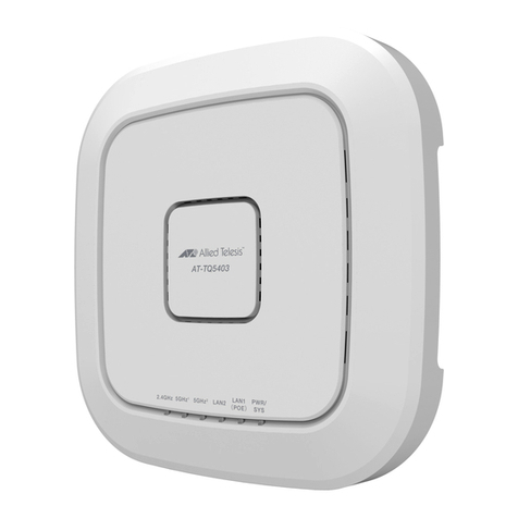
Allied Telesis AT-TQ Series User manual

Allied Telesis

Allied Telesis AT-TQ Series User manual

Allied Telesis AT-TQ1402 Series User manual

Allied Telesis

Allied Telesis AT-TQ1402 Series User manual

Allied Telesis TQ6000 GEN2 User manual

Allied Telesis

Allied Telesis TQ6000 GEN2 User manual

Allied Telesis AT-TQ6602 GEN2 User manual

Allied Telesis

Allied Telesis AT-TQ6602 GEN2 User manual

Allied Telesis AT-TQ2403 User manual

Allied Telesis

Allied Telesis AT-TQ2403 User manual

Allied Telesis AT-WA7400 User manual

Allied Telesis

Allied Telesis AT-WA7400 User manual

Allied Telesis TQ6702 GEN2 User manual

Allied Telesis

Allied Telesis TQ6702 GEN2 User manual

Allied Telesis AT-TQ4600 User manual

Allied Telesis

Allied Telesis AT-TQ4600 User manual
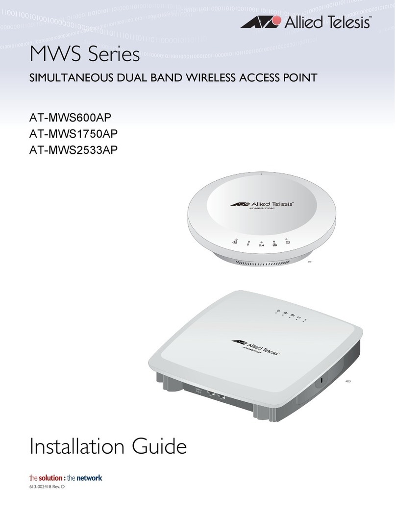
Allied Telesis AT-TQ4600-OF13 User manual

Allied Telesis

Allied Telesis AT-TQ4600-OF13 User manual

Allied Telesis AT-TQ6602 User manual

Allied Telesis

Allied Telesis AT-TQ6602 User manual

Allied Telesis TQ5403 User manual

Allied Telesis

Allied Telesis TQ5403 User manual
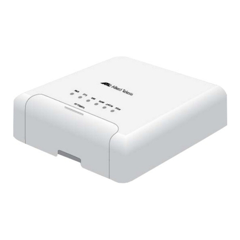
Allied Telesis AT-TQ4600 User manual

Allied Telesis

Allied Telesis AT-TQ4600 User manual

Allied Telesis AT-TQ2403 User manual

Allied Telesis

Allied Telesis AT-TQ2403 User manual

Popular Wireless Access Point manuals by other brands

Ceragon FA4800 user manual

Ceragon

Ceragon FA4800 user manual

ORiNG IAP-320+ user manual

ORiNG

ORiNG IAP-320+ user manual

3Com OfficeConnect 3CRWE454G75 Quick start guides

3Com

3Com OfficeConnect 3CRWE454G75 Quick start guides

Arris Ruckus T310c Quick setup guide

Arris

Arris Ruckus T310c Quick setup guide

Ruijie Networks RG-AP3220 Series Hardware  installation and reference guide

Ruijie Networks

Ruijie Networks RG-AP3220 Series Hardware installation and reference guide

3Com 3CRWE91096A - Wireless LAN Building-to-Building... datasheet

3Com

3Com 3CRWE91096A - Wireless LAN Building-to-Building... datasheet

D-Link DWL-2130AP - xStack - Wireless Access Point Quick installation guide

D-Link

D-Link DWL-2130AP - xStack - Wireless Access Point Quick installation guide

D-Link DWL-3200AP - AirPremier - Wireless Access... product manual

D-Link

D-Link DWL-3200AP - AirPremier - Wireless Access... product manual

Relay2 RA621EX Hardware installation guide

Relay2

Relay2 RA621EX Hardware installation guide

D-Link AirPremier N DAP-2360 Quick install guide

D-Link

D-Link AirPremier N DAP-2360 Quick install guide

Ubiquiti UF-Nano quick start guide

Ubiquiti

Ubiquiti UF-Nano quick start guide

Fortinet FortiAP 222E quick start guide

Fortinet

Fortinet FortiAP 222E quick start guide

Motion CM-20 manual

Motion

Motion CM-20 manual

Gemtek WIXS-181 Quick installation guide

Gemtek

Gemtek WIXS-181 Quick installation guide

D-Link DAP-1533 Quick install guide

D-Link

D-Link DAP-1533 Quick install guide

Planet 802.11g Wireless Access Point / Bridge... user manual

Planet

Planet 802.11g Wireless Access Point / Bridge... user manual

Ruijie Networks RG-AP820-I Hardware  installation and reference guide

Ruijie Networks

Ruijie Networks RG-AP820-I Hardware installation and reference guide

TP-Link Auranet EAP110 Quick installation guide

TP-Link

TP-Link Auranet EAP110 Quick installation guide

manuals.online logo
manuals.online logoBrands
  • About & Mission
  • Contact us
  • Privacy Policy
  • Terms and Conditions

Copyright 2025 Manuals.Online. All Rights Reserved.