manuals.online logo
Brands
  1. Home
  2. •
  3. Brands
  4. •
  5. Allied Telesis
  6. •
  7. Wireless Access Point
  8. •
  9. Allied Telesis TQ6702e GEN2 User manual

Allied Telesis TQ6702e GEN2 User manual

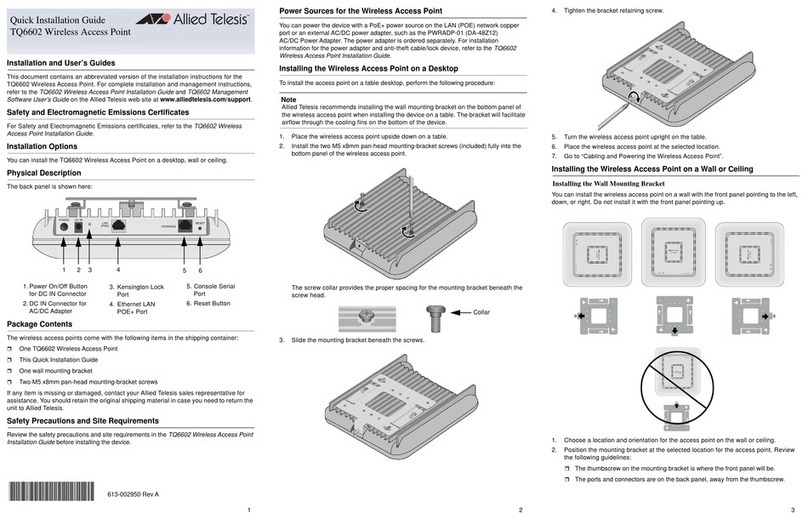
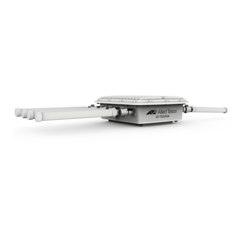
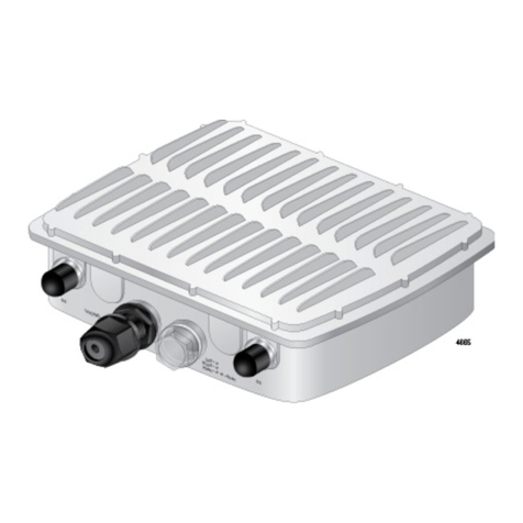
TQ6702e GEN2 Wireless Access Point
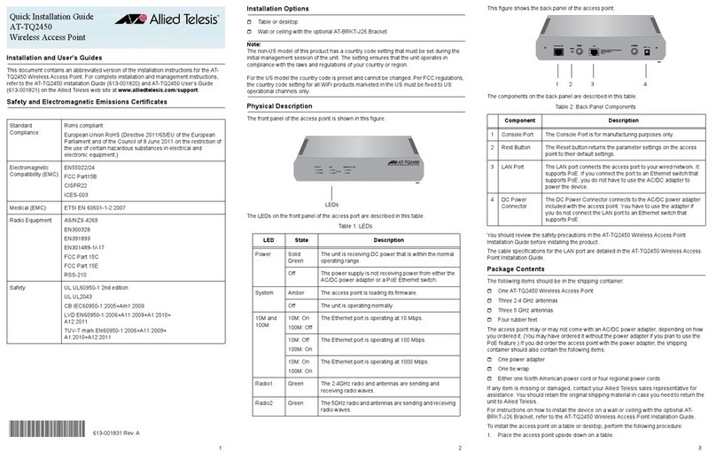
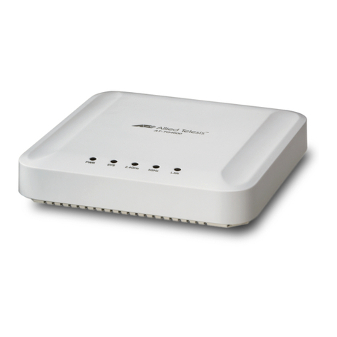
The access point model included in this Quick Installation guide is:
AT-TQ6702e GEN2
Installation and User’s Guides
This document contains an abbreviated version of the installation instructions for the
TQ6702e GEN2 Wireless Access Point. For complete installation and management
instructions, see the TQ6702e GEN2 Wireless Access Point Installation Guide and
TQ6702e GEN2 Management Software User’s Guide on the Allied Telesis web site at
www.alliedtelesis.com/library.
Safety Precautions and Site Requirements
Review the safety precautions and site requirements in the TQ6702e GEN2 Wireless
Access Point Installation Guide before installing the device.
Safety and Electromagnetic Emissions Certificates
This device complies with Part 15 of FCC Rules, Directive 2014/53/EU issued by the
Commission of the European Community, some other safety, electromagnetic emission,
and radio certificates.
Physical Description
TQ6702e Access Point Package Contents
If any item is missing or damaged, contact your Allied Telesis sales representative for
assistance. Retain the original shipping material to return the unit to Allied Telesis.
Attaching the Ground Cable to the Access Point
1. Select a ground post on the access point for the ground wire.
The access point has two ground posts on the bottom panel. Use either post.
2. Insert the screw through the ground lug on the ground wire and secure the wire to
the selected ground post on the access point, using a Phillips-head screwdriver.
Note
The ground wire must be 20AWG or larger; the screw must be 3.5mm or larger.
3. Attach the other end of the ground wire to a circuit breaker, ground rod, or earth
ground.
Note
Keep the ground cable as short as possible; remove any extra cable.
Connecting an Ethernet Cable to the Access Point
1. Place the access point on a table or desk.
2. Unscrew the cap on the LAN port and remove it from the access point.
3. Disassemble the sealing nut, clamping claw, and sealing insert.
4. Slide the Ethernet LAN cable through the sealing nut and clamping claw.
5. Open the sealing insert and slip it onto the Ethernet wire.
The end with the groove needs to be towards the clamping claw. The fingers on the
clamping claw need to be pointing towards the sealing nut.
Quick Installation Guide
Ethernet LAN
and PoE++ Port
LEDs and
Reset Button
5GHz Antenna
Connectors
2.5G/ 5GHz Dual-band
Antenna Connector
2.5G/ 5GHz Dual-band
Antenna Connector
2.5 / 5GHz Dual-band Antenna Connectors
Gore
® Vent
5GHz Antenna Connectors
Front Panel
Back Panel
613-003135 Rev C
*613-003135 Rev C*
Four 5GHz single band
antennas
Four 2.4G/5GHz dual band
antennas
One mounting base
Four sets of a screw (M6xP1.0
16mm), washer, and spring
washer for the mounting base
One pole-mount bracket
Four sets of a Hex-head bolt,
washer, and spring washer for
pole-mount bracket
Two U-bolts
Four nuts for the U-bolts
Two pole straps
One 8AWG ground cable
One screw with a washer and
spring washer for the ground
cable
Eight external surge protectors
with nuts, metal washer, and
rubber washers
Ground
Lug
Ground Post
Ground Post
Clamping Claw
Sealing
Nut
1 2 3
6. Slide the sealing insert into the clawing clamp and slide the clamping claw into the
sealing nut.
7. Connect the RJ-45 connector on the Ethernet cable into the Ethernet LAN port inside
the sealing assembly. and tighten the sealing nut on the access point.
Note
The next step powers on the access point by attaching the Ethernet cable to a port
on a PoE++ source device. Allied Telesis recommends not performing the step
until you have completed all of the installation procedures.
8. Connect the other end of the Ethernet cable to a port on a PoE++ source device,
such as a PoE++ switch.
Attaching the Antennas to the Access Point
1. Remove the blind caps covering the antenna connectors.
2. Screw a surge protector to an antenna connector.
3. Screw the nut onto the surge protector and install the metal washer and rubber
washer, in that order, on the surge protector.
Note
You must install 5GHz antennas to 5GHz antenna connectors and 2.4GHz
antennas to 2.4GHz antenna connectors.
4. Screw an antenna onto the surge protector and tighten the nut against the antenna
to secure the antenna.
5. Repeat this procedure to install the remaining antennas.
Installation Orientation
The access point must be installed on a pole or wall with the front panel facing down.
Installing the Access Point on a Wall
1. Hold the mounting base on the wall at the desired location for the access point and
mark the four mounting base holes with a pencil.
Note
The mounting base can be in a vertical or horizontal position.
c
2. Pre-drill the marked locations on the wall.
3. Install the provided wall anchors in the holes.
4. Place the access point upside-down on a table or desk.
5. Attach the mounting base to the bottom of the access point with the provided screws,
spring washers, and washers, using a Phillips-head screwdriver.
6. Attach the access point to the wall with the provided screws.
Installing the Access Point on a Pole
Groove
Sealing Insert
Sealing
Nut
Fingers
Clamping Claw
Nut
Metal washer
Rubber washer
Front Panel
Back Panel
Screw
(M6xP1.0 16mm)
Spring Washer
Washer
Correct Order of
Washers
Using the U-bolts and
Pole Mount Bracket
Using the Pole Straps
and Mounting Base
Pole
straps Mounting
base
Pole-mount bracket
4 5 6
Installing the Access Point on a Pole Using the U-Bolts and Pole-
Mount Bracket
1. Attach the pole mount brackets to the pole with the two U-bolts.
2. Attach the access point to the pole-mount bracket with the screws using a
Phillips-head screwdriver.
Adjusting the Position Upwards or Downwards
1. Loose the two bolts located on the sides of the pole mount brackets using an
adjustable wrench or a 10mm socket and ratchet.
2. Adjust the angle of the access point upward or downward.
3. Tighten the bolts.
Vertical Pole and Horizontal Pole
Installing the Access Point on a Pole Using the Pole Straps and
Mounting Base
1. Attach the mounting base to the bottom of the access point with the provided screws,
spring washers, and washers, using a Phillips-head screwdriver.
Note
Attach the ground cable to the access point before attaching the mounting base..
2. Thread one pole strap through the holes marked 1 to attach to the mounting base.
Repeat to thread the other pole strap.
Note
Use the holes marked 2 to install the access point on a horizontal pole.
3. Wrap the pole straps around the pole.
4. Insert the ends of the pole straps beneath the strap screws.
5. Tighten the screws with a Phillips-head screwdriver to secure the access point to the
pole.
Starting the Initial Management Session
The access point firmware includes a DHCP client. The default setting for the client is
enabled. When you power on the access point for the first time, it queries the subnet on the
LAN port for a DHCP server. If a DHCP server responds to its query, the unit uses the IP
address the server assigns to it.
1. Start the web browser on your management workstation.
2. Enter the IP address of the wireless access point in the URL field of the web
browser. The address is one of the following:
If your network does not have a DHCP server, enter the default address
192.168.1.230.
If your network has a DHCP server, enter the IP address the DHCP server
assigned to the access point.
The wireless access point displays the logon prompt.
3. Enter “manager” for the username and “friend” for the password. The username and
password are case-sensitive.
Setting the Country Setting
The non-US model of this product has a country code setting that must be set during the
initial management session of the unit. The setting ensures that the unit operates in
compliance with the laws and regulations of your country or region.
The country code for the US model is preset and cannot be changed. Per FCC
regulations, the country code setting for all WiFi products marketed in the US must be
fixed to US operational channels only.
LEDs
‘
T
Reseting the Device
Resetting the device makes the parameter settings of the device to their
default values.To reset the device, remove the transparent cap on the front
panel and press the black button for five seconds and release.
2
2
1
1
LED State Description
LAN Solid Green The LAN port is receiving power from a PoE++
source device and is operating normally.
Blinking
Green
The LAN port is receiving power from a PoE++
source device and is transmitting/receiving
network traffic.
Off The access point is powered off because the
LAN port is not receiving power from a PoE++
source device.
WLAN Solid Green One or both radios (i.e., Radio1, Radio2, or
both) are enabled.
Off All radios are disabled or the access point is
powered off.
Power Solid Green The power from the PoE++ source device is
within the normal operating range.
Blinking
Green
The access point is booting up or upgrading its
firmware.
Off The access point is not receiving power from a
PoE++ source device on the Ethernet LAN port,
7 8 9
Optional Patch Antenna and Extension Cable
Allied Telesis offers the optional TQ0301 dual-band patch antenna with four 2 meter long
cables. In addition, you can use the TQ0064 10-meter RF extension cable with the
TQ0301 antenna. To use the TQ0301 antenna and TQ0064 cable, you must purchase
them in addition to the access point.
TQ0301 Dual-band Patch Antenna Package Contents
TQ0064 Extension Cable Package Content
Attaching the Cables to the TQ0301 Patch Antenna
Allied Telesis offers two types of cables for the TQ0301 patch antenna: Two meter cable:
comes with the TQ0301 and TQ0064 10 meter cable.
Installing the TQ0301 Patch Antenna on a Pole
The TQ0301 patch antenna can be mounted on a pole with the pole-mount brackets.
Note
The TQ0301 patch antenna must installed with the cable connectors facing down.
1. Remove the connector blind caps covering the antenna connectors.
2. Attach the N-Jack adapters to the two meter cables.
3. Screw the cables to the antenna connectors.
Installing the TQ0301 Antenna and AT-TQ6702e GEN2 Access Point
The TQ6702e GEN2 access point has two types of antenna connectors:
5GHz antenna connectors
2.4G/5GHz dual-band antenna connectors
Attaching the Cable to the Access Point
Note
You must install 5GHz antennas to 5GHz antenna connectors and 2.4GHz
antennas to 2.4GHz antenna connectors.
1. Remove the connector blind caps covering the antenna connectors.
2. Screw the cable to an antenna connector.
Safety and Electromagnetic Emissions Certificates
This device complies with Part 15 of FCC Rules, Directive 2014/53/EU issued by the
Commission of the European Community, some other safety, electromagnetic emission,
and radio certificates.
The operating frequencies and maximum transmission power levels for wireless devices
operated in the EU & UK are listed below:
Note
Contact Allied Telesis for the EU conformity statement. To contact Allied Telesis,
visit the web site at www.alliedtelesis.com/contact.
 
  

Copyright  2023 Allied Telesis, Inc. All rights reserved.No part of this publication may be
reproduced without prior written permission from Allied Telesis, Inc.
Allied Telesis and the Allied Telesis logo are trademarks of Allied Telesis, Incorporated.
All other product names, company names, logos or other designations mentioned herein
are trademarks or registered trademarks of their respective owners.
Allied Telesis, Inc. reserves the right to make changes in specifications and other
information contained in this document without prior written notice. The information
provided herein is subject to change without notice. In no event shall Allied Telesis, Inc.
be liable for any incidental, special, indirect, or consequential damages whatsoever,
including but not limited to lost profits, arising out of or related to this manual or the
information contained herein, even if Allied Telesis, Inc. has been advised of, known, or
should have known, the possibility of such damages.
Dual-band Patch Antenna
(Bracket Assembly
attached)
Four Cables (2 m)
Four SMA to N jack
conversion adapters
The adapters are not used for the TQ6702e GEN2
access point.
Two metal protective caps
10 meter Cable
Pole-mount brackets
AT-TQ6702e GEN2 with the Dipole Antennas (default)
2412-2472 MHz 5180-5240 MHz 5260-5320 MHz 5500-5700 MHz
Beamforming 19.98 dBm 22.81 dBm 22.7 dBm 29.75 dBm
Non-Beamforming 19.96 dBm 22.87 dBm 22.65 dBm 29.87 dBm
AT-TQ6702e GEN2 with the Optional AT-TQ0301 Patch Antenna
2412-2472 MHz 5180-5240 MHz 5260-5320 MHz 5500-5700 MHz
Beamforming 19.98 dBm 22.91 dBm 22.97 dBm 29.96 dBm
Non-Beamforming 19.98 dBm 22.85 dBm 22.87 dBm 29.96 dBm
* This equipment should be installed and operated with a minimum distance of 20 cm between the
radiator and your body.
10 11 12
Other manuals for TQ6702e GEN2

1

Other Allied Telesis Wireless Access Point manuals

Allied Telesis TQ5403e User manual

Allied Telesis

Allied Telesis TQ5403e User manual

Allied Telesis AT-TQ5403e-00 User manual

Allied Telesis

Allied Telesis AT-TQ5403e-00 User manual

Allied Telesis AT-TQ4600 User manual

Allied Telesis

Allied Telesis AT-TQ4600 User manual

Allied Telesis AT-AR240E User manual

Allied Telesis

Allied Telesis AT-AR240E User manual

Allied Telesis AT-TQ2450 User manual

Allied Telesis

Allied Telesis AT-TQ2450 User manual

Allied Telesis AT-TQ6602 User manual

Allied Telesis

Allied Telesis AT-TQ6602 User manual

Allied Telesis AT-TQ5403e User manual

Allied Telesis

Allied Telesis AT-TQ5403e User manual

Allied Telesis AT-TQ4600 User manual

Allied Telesis

Allied Telesis AT-TQ4600 User manual

Allied Telesis AT-TQ6602 User manual

Allied Telesis

Allied Telesis AT-TQ6602 User manual

Allied Telesis AT-TQ Series User manual

Allied Telesis

Allied Telesis AT-TQ Series User manual

Allied Telesis TQ6602 User manual

Allied Telesis

Allied Telesis TQ6602 User manual

Allied Telesis AT-WL2411 User manual

Allied Telesis

Allied Telesis AT-WL2411 User manual

Allied Telesis AT-WA7400 User manual

Allied Telesis

Allied Telesis AT-WA7400 User manual

Allied Telesis TQ1402 User manual

Allied Telesis

Allied Telesis TQ1402 User manual

Allied Telesis AT-TQ6702 GEN2 User manual

Allied Telesis

Allied Telesis AT-TQ6702 GEN2 User manual

Allied Telesis AT-TQ4400e User manual

Allied Telesis

Allied Telesis AT-TQ4400e User manual

Allied Telesis AT-TQ2403 User manual

Allied Telesis

Allied Telesis AT-TQ2403 User manual

Allied Telesis TQ6000 GEN2 User manual

Allied Telesis

Allied Telesis TQ6000 GEN2 User manual

Allied Telesis AT-TQ5403 Series User manual

Allied Telesis

Allied Telesis AT-TQ5403 Series User manual

Allied Telesis AT-WA7500 User manual

Allied Telesis

Allied Telesis AT-WA7500 User manual

Allied Telesis AT-TQ5403 Series User manual

Allied Telesis

Allied Telesis AT-TQ5403 Series User manual

Allied Telesis AT-AP500 User manual

Allied Telesis

Allied Telesis AT-AP500 User manual

Allied Telesis AT-MWS2533AP User manual

Allied Telesis

Allied Telesis AT-MWS2533AP User manual

Allied Telesis TQ6000 GEN2 User manual

Allied Telesis

Allied Telesis TQ6000 GEN2 User manual

Popular Wireless Access Point manuals by other brands

HP E-MSM466-R install guide

HP

HP E-MSM466-R install guide

Cisco Meraki Using

Cisco

Cisco Meraki Using

Extreme Networks Altitude 4600 Series installation guide

Extreme Networks

Extreme Networks Altitude 4600 Series installation guide

Colubris Networks MARP-330r quick start guide

Colubris Networks

Colubris Networks MARP-330r quick start guide

Planet WNAP-7300 Quick installation guide

Planet

Planet WNAP-7300 Quick installation guide

Zcom XG-580 PLUS user manual

Zcom

Zcom XG-580 PLUS user manual

AirLive AirLive WMU-6500FS user manual

AirLive

AirLive AirLive WMU-6500FS user manual

Zcom SP230 Series quick start guide

Zcom

Zcom SP230 Series quick start guide

Planet WNAP-W2201A user guide

Planet

Planet WNAP-W2201A user guide

Planet WAP-1963 user manual

Planet

Planet WAP-1963 user manual

AirLive AirLive WMU-6500FS Quick setup guide

AirLive

AirLive AirLive WMU-6500FS Quick setup guide

AirLive AC-1200R Quick installation guide

AirLive

AirLive AC-1200R Quick installation guide

Abus HomeTec Pro ABHT10137 operating instructions

Abus

Abus HomeTec Pro ABHT10137 operating instructions

Planet WNAP-W2200UE user manual

Planet

Planet WNAP-W2200UE user manual

Multitech Conduit AP MTCAP2-L4E1-868-042A-POE user guide

Multitech

Multitech Conduit AP MTCAP2-L4E1-868-042A-POE user guide

Planet WNAP-6305 manual

Planet

Planet WNAP-6305 manual

AirLive AirMax5N user manual

AirLive

AirLive AirMax5N user manual

Planet WAP-1965 user manual

Planet

Planet WAP-1965 user manual

manuals.online logo
manuals.online logoBrands
  • About & Mission
  • Contact us
  • Privacy Policy
  • Terms and Conditions

Copyright 2025 Manuals.Online. All Rights Reserved.