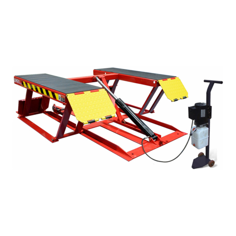
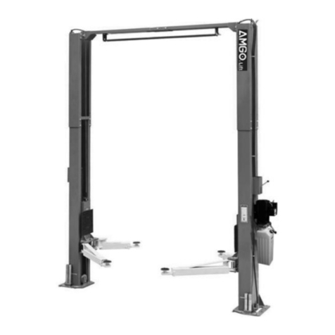
AMGO MC-1200 Manual

Motorcycle lift
MC-1200

CONTENTS
I. Product Features and Specifications…………………..................…….1
II. Installation requirement...…………………………..................……..…2
III. Steps of Installation...………………………….................…………..…3
IV. Exploded View………………………………………….....................….…..8
V. Test Run…….……………………………………..…….…..........................11
VI. Operation Instruction.…………………………................…..…….…...12
VII. Maintenance……………………………………..................….……….....13
VIII. Trouble shooting.……………………………….…................……….…14
IX. MC-1200 parts list……..…………….………...................................…15

1
I .PRODUCT FEATURES AND SPECIFICATIONS
Motorcycle lift MC-1200:
●Hydraulic cylinders is designed and manufactured according to
standard, utilizing imported seals
● Self-lubricating UHMW Polyethylene sliders and bronze bush
● Non-skid diamond platforms
●Automatic safety release system
● Optional: Width extension kit and platform extension kit
MODEL MC-1200 SPECIFICATION
Model Capacity Lifting
Height
Lifting
Time
Overall
Length
Overall
Width
Minimum
Height
Gross
weight Motor
MC-1200 1200lbs 43’’ 23s 108’’ 29-1/2’’ 6’’ 639lbs 0.75HP
Fig.1

2
II . INSTALLATION REQUIREMENT
A. TOOLS REQUIRED
Rotary Hammer Drill (Φ19) Ratchet Spanner with Socket:(28#)
Screw
English Spanner (12")
Wrench Set:(13#、15#、17#、19#)
Fig.2
Pliers
Grease gun
Hook Spanner
(40
~
42mm)

3
B. SPECIFICATIONS OF CONCRETE
Specifications of concrete must be adhere to the specifications as
following. Failure to do so may result in lift and/or vehicle falling.
1. Concrete must be thickness 4’’ minimum and without reinforcing steel bars,and
must be dried completely before lift installation.
2. Concrete must be of test strength 3000PSI minimum.
C. POWER SUPPLY
The power capacity must be more than 3.0HP, The source cable size must be
0.003875sq.in and in good condition of contacting with floor.
III.STEPS OF INSTALLATION
A. Check the parts before assembly to make sure all the parts are completed.
1. Packaged cargo( lift, drive-in ramp, Parts box, control cabinet). Move the parts
aside, open the outer packing and check the parts according to the shipment parts
list. see Fig.3
Fig.3
57

4
2. Open the parts box, check the parts according to the parts list (See Fig. 4).
3. Open the parts bag, check the parts according to the parts list (See Fig. 5).
B. Put the lift and control cabinet in good order and connect the oil hose, see
Fig.6
Fig.4
Fig.5
Fig.6
63
62
51-1
63
51
51-2

5
C. Install Electrical System
1. Schematic circuit diagram(Fig.7)
D. Fastening all the oil hose fittings, fill the power unit with right amount
hydraulic oil ( in order to ensure the working life of hydraulic system and the
machine reach the best performance, please fill in the No.46 high quality
anti-wear hydraulic oil. )
Fig.7
Single Phase
Switch button
SB(UP)

6
E. Install adjustable fixing device. See Fig.8
1.After connecting the wire, lift the motorcycle lift to a suitable height, install the
adjustable fixing device according to below photo;
2. The adjustable fixing device can be chosen to install in different installed position of
the platform.
Fig.8
52
55

7
F. Install width extension kit(optional).See Fig.9
G. Install platform extension kit(optional).See Fig.10
Note: Connect the holes on platform extension kit and the platform. Install the
adjustable fixing device on the platform extension kit.
64
65
66
67
68
Fig.9
Fig.10
73
69
70
71
72

8
IV. EXPLODED VIEW
MODEL:MC-1200
Fig.11

9
Power unit stand
Cylinder
Fig.13
Fig.12
61
60
59
53
200

10
Power unit
Illustration of hydraulic valve for power unit(110V/60Hz/1 phase)
Handle of
Release valve
Release valve
Throttle
Oil Outlet
Oil return port
Protective ring
Fig.15
110V/60Hz/1 phase
Fig.14
Check valve
Relif valve
Microswitch

11
V. TEST RUN
1. Install anchor bolts. see Fig.16
Install the anchor bolts to fix the machine after installing.
2. Adjust safety cable
Raise the lift to the highest position(See Fig.17), rotating the safety lock handle as
the direction of arrow. Loosen the screw of the safety cable by spanner, lift up the
safety lock plate from the rack about 1/2’’~3/4’’ (See Fig.18), then tighten the
safety cable by spanner
`
Steps:
Note: Twisting force is (150N.m)492lbf.ft for fixing the anchor screw ,
knock the anchor bolt into the ground at least 3-1/2’’
Fig.17 Fig.18
Safety
handle
1/2’’~3-4’’
3-1/2’
Drilling
Bolting
Tighten
Tighten screw
54
Fig.16

12
VI. OPERATION INSTRUCTIONS
1. Install well the oil hose between cylinder and power unit, connect well the
wire, the motorcycle lift can be used.
2. Raise up the lift without vehicle for testing.
3. To lift vehicle
Lower the lift to the lowest position, loosen the adjustable fixing device. Move the
motorcycle to the platform, put the wheel in the adjustable fixing device, set well the
motorcycle. Put up the foot stool of vehicle. Clamp the tire by the rotated handle.
Tighten the Tension bandage. Make sure the wheel is tightened and the Tension
bandage is fixed before using. See Fig.19.
4. To lower the lift: Raise the lift for several seconds. Rotate the safety lock handle
downward (see Fig.20) to release the safety device.. After the safety device is
released(see Fig.21), press the release handle in the power unit, the lift would be
lowered.
Safety device is released
Fig.21
Safety device is locked
Fig.20
56 Tie kits(Optional)
Fig.19
(Put up the foot stool
Of vehicle

13
VII. MAINTENANCE SCHEDULE
Monthly maintenance:
1. Lubricate all moving parts with lubricant. Fig.22
2. Check all connectors, bolts and pins to insure proper mounting.
3. Make a visual inspection of all hydraulic hoses/lines for possible wear or leakage
Every six months:
1. Make a visual inspection of all moving parts for possible wear, interference or
damage.
2. Check all fasteners and re-torque
Fig.22

14
VIII.TROUBLE SHOOTING
NO TROUBLE CAUSE REMEDY
1 Motor does not run
1. Button does not work 1. Replace button
2. Wiring connections are not
in good condition
2. Repair all wiring connections
3. Motor burned out 3. Repair or replace motor
4. AC contactor burned out 4. Replace AC Contactor
2 Motor runs but the lift
is not raised
1. Motor runs in reverse
rotation
1.Reverse two power wire
2. Release Valve in damage 2. Repair or replace
3. Gear Pump out of operation
3. Repair or replace
4. Relief Valve or Check Valve
in damage
4. Repair or replace
5. Low oil level 5. Fill tank
6. Overload lifting or low
pressure
6.Check load or adjust the pressure
3 Lift does not stay up
1. Release Valve out of work Repair or replace
2. Relief Valve or Check Valve
leakage
Repair or replace
3. Cylinder or Fittings leaks Replace fitting and oil seal
4 Lift rises slowly
1. Oil line is jammed 1. Clean the oil line
2.Motor running on low
voltage 2. Check Electrical System
3. Oil mixed with air 3. Fill tank
4. Gear Pump leaks 4. Repair or replace
5. Overload lifting 5. Check load
5 Lift cannot lower
1. Safety device are not in
activated
1. Release the safety device
2. Release Valve in damage 2. Repair or replace
3. Oil system is jammed 3. Clean the oil system

15
IX. PARTS LIST
Item Part# Description QTY. Note
1 11720118 Platform 1
2 11720021 Cover plate of Platform 1
3 10217069 Hex bolt 2
4 11720123 Drive-in ramp 1
5 11720120 Outer scissor assy. 1
6 11720119 Inner scissor assy. 1
7 10610023 Sliding block 4
8 11720122 Pin for safety device 1
9 10206019 Snap ring 1
10 10720061 Socket bolts 1
11 11720125 Safety device assy. 1
12 11720121 Base assy. 1
13 10620022 Self locking nut 2
14 10203004A Bronze bush 8
15 11720007 Pin for Scissor 2
16 10720003 Spring 4
17 11720012 Pin for Spring 4
18 10209025 Pin 6
19 10640006A Cylinder Base Pinφ25 1
20 10640007 Cylinder 1
21 11640057 Pin For Cylinder Connecting 1
22 10206032 Snap ring 12
23 11720009 Connecting pin 4
24 10620136 Pin roll 1
25 11720111 Connecting pin for safety lock 1
26 11720110 Connector bush 1
27 10420018 Self locking nut 1
28 10720102 Socket bolt 1
29 10209021 Hex nut 6
30 10720043 Rubber pad 2
31 10209022 Washer 6
32 10209039 Washer 6
33 10720002 Socket bolt 6
34 11720028 Fixed frame 1
35 10720044 Rubber pad 2
36 10209019 Socket bolt 24
37 11720048 Tire stop tube assy. 1
38 10720045 Washer 1
39 10209033 Washer 6

16
Item Part# Description QTY. Note
40 10209034 Lock washer 7
41 10420043 Socket bolt 6
42 11720017 Adjusted shaft 1
43 11720016 Connecting plate for handle 1
44 10206023 Self locking nut 1
45 11720015 Fixed Bolt for operating handle 1
46 11720018 Operating handle 1
47 10206006 Washer 1
48 11720032 Adjustable fixing device 1
49 11720031 Active tube assy. 1
50 11720030 Adjustable frame 1
51 10420244 Transition fitting 1
51-1 10420245 Transform fitting 1
51-2 10420119 Straight fitting 1
52 10206156 Tool tray 1
53 11720131 Power unit dolly 1
54 10620071 Anchor bolt 4
55 11720100 Tool tray frame 1
56 10720014 Tension bandage 1
57 10720501 Parts box 1
58 10640050 Socket bolt 2
59 10209005 Self lock nut 4
60 10209004 Rubber ring 4
61 10209003 Hex bolt 4
62 10209060 90°fitting for power unit 1
63 10440042 Oil hose 1
200 81513024 Manual power unit 1
Optional: Width extension kits
64 11720124 Connecting shaft 2
65 11720035 Width extension platform 2
66 10209012 Hair pin 4
67 10217069 Hex bolt 4
68 11720034 Width extension drive-in ramp 2
Optional: Extension kits
69 10209126 Hex bolt 4
70 10209039 Lock Washer 4
71 10209022 Washer 4
72 10209021 Hex nut 4
73 11720126 Extension platform 1

17
Parts for cylinder
Item Part# Description QTY. Note
20-1 11640030A Bore Weldment 1
20-2 11640031A Piston Rod 1
20-3 10201034 Bleeding Plug 1
20-4 11201033 Head Cup 1
20-5 10209078 Dust Ring 1
20-6 10201032 0-Ring 1
20-7 10201035 0-Ring 1
20-8 11201028 piston 1
20-9 10206069 0-Ring 1
20-10 10201031 0-Ring 1
20-11 10201030 Y-Ring 1
20-12 10201029 Support Ring 1
20-13 10206071 Nut 1
20-14 10620064 Oil nozzle 2

18
Parts for power unit, 11V/60Hz/1 phase
Item
Part#
Description
QTY.
Note
1
81400533 Motor 1
2
81400363 Motor connecting shaft 1
3
81400362 Manifold block 1
4
10209149 Wash 4
5
81400276 End plug 1
6
81400259 Red plastic plug 1
7
85090142 Hex bolt 4
8
81400280 Gear pump 1
9
81400294 Buffer valve 1
10
10209034 Washer 2
11
81400295 Socket bolt 2
12
81400365 O ring 1
13 10209152 Tie 1
14 85090167 Magnet 1
15 81400290 Filter 1
16 81400557 Microswitch 1
17 81400296 Nut 1
18 81400459 Throttle valve body 1
19 10209069 O ring 1
20 81400266 Relief valve 1
21 81400284 Inner hex plug 1
22 10720118 Pin 1
23 10720121 Handle for release valve 1
24 10209020 Plastic ball 1
25 81400125 Nut for release valve 1
26 81400124 Shim for release valve 1
27 81400449 Valve seat 1
28 070001 Release valve 1
29 070002 Check valve 1
30 81400288 Oil inlet pipe 1
31 81400289 Oil return pipe 1
32 81400364 Clamps 1
33 81400263 Filter cap 1
34 81400320 Reservoir 1
Table of contents
Other AMGO Lifting System manuals
Popular Lifting System manuals by other brands

HiGH-LiFT
HiGH-LiFT OPK-ME500 Manual instruction

Telpro
Telpro PaneL Lift 439 Operator's manual

Fantek
Fantek FT-6860 operating instructions

Milltronics
Milltronics MWL instruction manual

Lift Tech Marine
Lift Tech Marine DC REMOTE GEN 2 owner's manual

BraunAbility
BraunAbility Century 2 NCL10000 Series Service manual