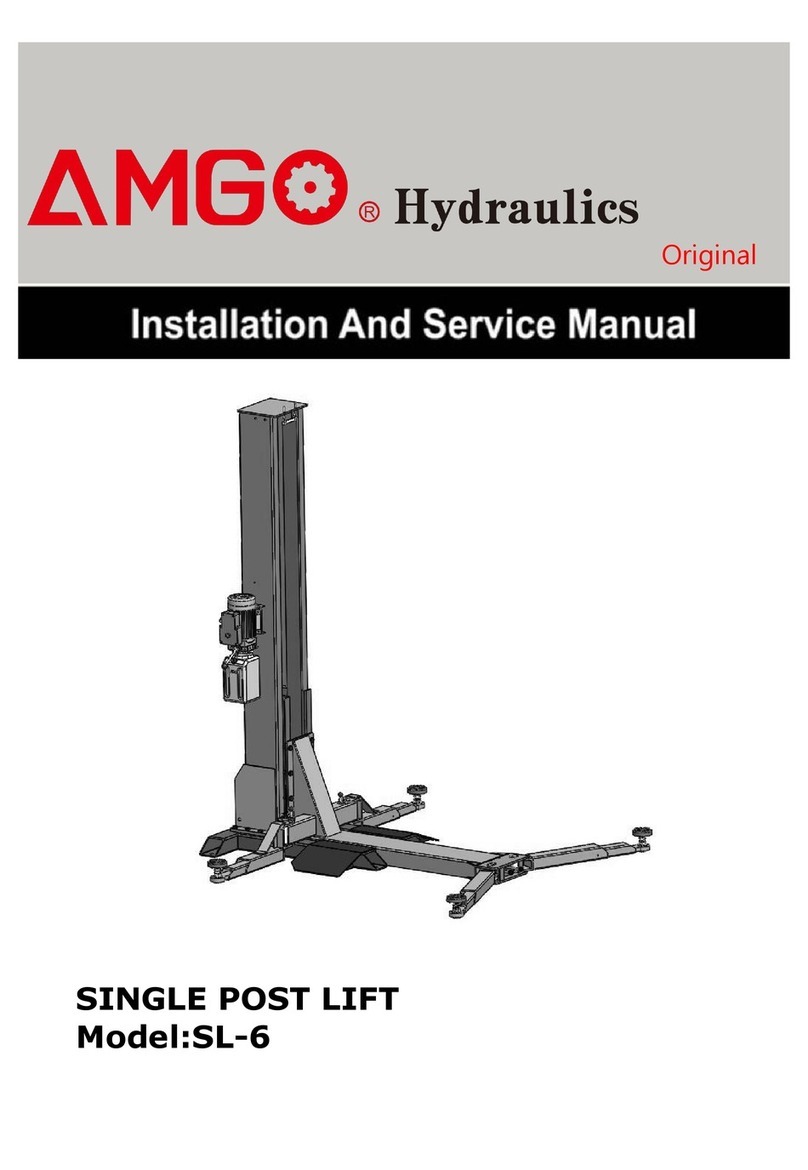
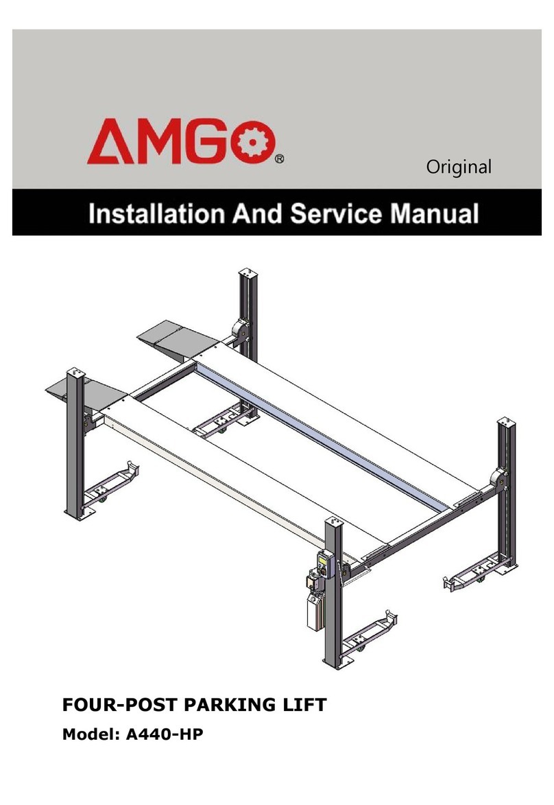
AMGO SPL-6 Manual

Single-post Parking Lift Model:
SPL-6
Original

CONTENTS
Product Features and Specifications ............................................................... 1
Installation Requirement ...............................................................................2
Steps of Installation .....................................................................................4
Exploded View ............................................................................................13
Test Run ....................................................................................................22
Operation Instruction .................................................................................. 24
Maintenance .............................................................................................. 25
Trouble Shooting ........................................................................................ 26
LIFT DISPOSAL ............................................................................................26

1
I. PRODUCT FEATURES AND SPECIFICATIONS
Single-post Parking Lift MODEL SPL-6
· Specially designed for parking.
· Dual safety device, No air source, manual safety lock release
· Non slip lifting platform
· H-shaped lifting platform with reinforced column to provide excellent stability
· Available for low ceilings garage of less than 110” (2800mm).
· Suitable for home garages and commercial applications,with limited floor space.
MODEL SPL-6 SPECIFICATIONS
Model Lifting
Capacity Lifting Height Lifting
Time
Overall
Height
Overall
Width
Outside Edge
of Runways Motor
SPL-6 6,000 lbs 74″ (1880mm) 84S(110V)
32S(220V)
108 7/8″
(2766mm)
111″
(2820mm)
82 3/8″
(2093mm)
1.0HP(110V)/
2.0HP(220V)
Fig.1

2
II. INSTALLATION REQUIREMENT
A. TOOLS REQUIRED
Carpenter’s Chalk Hammer
Screw sets
Level Bar
Tape Measure(7.5mm)
English Spanner(12″)
Pliers Socket Head Wrench (4#、5#、6#)
Wrench set:((10#、13#、14#、15# Rotary Hammer Drill (Φ3/4)
17#、19#、24#、27#)
Fig.2

3
B. STORAGE AND INSTALLATION REQUIRMENT
Keep or install the equipment in shaded, normal temperature, dry and ventilated
environment.
SPECIFICATIONS OF CONCRETE (See Fig. 3)
Specifications of concrete must be adhered to the specification as following.
Failure to do so may result in lift and/or vehicle falling.
1. Concrete must be thickness 5”(120mm) minimum and without reinforcing steel bars,
and must be totally dry before lift installation.
2. Concrete must be in good condition and must be of test strength 3,500psi (245kg/cm²)
minimum.
3. Floors must be level with no cracks or holes.
C. POWER SUPPLY
The electrical source must be 3.0HP minimum. The source cable size must be 2.5mm².
73
≥5”
Concrete test strength 3,500psi
Fig.3

4
III. STEPS OF INSTALLATION
A. Location of installation
Check and insure the installation location (concrete, layout, space size etc.) is suitable for
lift installation.
B. Check the parts before assembly
1. Packaged lift and hydraulic power unit (See Fig. 4)
2. Take off the packaging on the machine Take off the packing rack.
3. Move aside the parts and check the parts according to the shipment parts list (See Fig.5
& 6)
Fig.4
Shipment list
Fig.5

5
4. Check the parts of the parts bag according to the parts bag list (See Fig. 7)
C. Lay the base flat to the ground, confirm installation place according to the
ground state, the main purpose is to save space. (See Fig.8)
Fig.8
15
Parts Box (65)
Fig.6
Fig.7
73

6
D. Fix anchor bolts
Using the prescribed rotary hammer drill, and drill all the anchor holes and install the
anchor bolts. Then tighten the anchor bolts (See Fig. 9)
Note: Torque of Anchors is 150N.m .Minimum embedment of Anchors is 4-3/8”.
E. Install column and lift platform
1.Lay the column flat to the ground. (See Fig.10)
2.Connecting oil hose of cylinder. (See Fig.11)
Fig.11
Fig.
9
66
Connecting oil hose to
the fitting of cylinder
4-3/8”
Pull out the carriage from
base plate about 200mm
Fig.10

7
3. Fix column to the base plate. (See Fig.12)
4. Install slider to the behind of lifting Platform (See Fig.13)
1
3
36
17
18
16
Fig.1
2
44
45
37-40
41-43
50
Slider fixed plate
Slider
Fig.13

8
5. Fixed the lifting platform to the carriage(See Fig.14)
E. Install power unit ,oil hoses and clip (See Fig.15)
Note: Tighten the oil hose fitting and power unit fitting to avoid oil leakage; Pay
attention to the direction of power unit fitting.
Please use Hydraulic Oil 46#
Fig.14
F
ig.1
5
46
48
47
49
20-22
Lock the nut with 19’’
wrench after installing the
fitting of power unit

9
G. Install electrical system
Connect the power source on the data plate of power unit.
Note: For the safety of operators, the power wiring must contact the earth well.
Single phase motor
1. Power supply wires (active wire L and neutral wire N) to terminals of AC
contactor marked L1, L3 respectively. Circuit diagram
2. Connecting the earth wire terminal of the motor.
H. Install lifting arms
Lifting the carriages to the suitable position,and then joint the arm to the carriage,used the
snap ring to limited the position after the PIN inserted completely and go though to bottom.
Fig. 16
Fig.
1
7
70
69
64

10
I. Install wheel assembly
1. Lifting the arm to the suitable position,align the cut of the platform with the square
tube of the arm and connect it with bolts(Wash can be add up and down side).Two
platform can be transferred and installation randomly. Connecting the arm and platform
after the 16 holes of platform are alignment. (Fig.18),
53-57
61-63
Fig.18

11
J. Install the drive-in ramp, platform and the base guide plate (Fig.19): After the
top plate is fixed, the two sides of the drive-in ramp and guide plate are bolted on both sides
of the top plate. The boarding guide plate is directly stuck in the middle of the base.
K. Install plastic baffle (Fig.20)
Fig.19
Guide plate
24
4
5
The plastic baffle
through here.
Chain clamp support plate
Fig.
2
0

12
L. Measure the vertical of the column with a horizontal ruler and correct the
vertical of the column with a horizontal adjustment pad.(Fig.21)
The horizontal ruler is from the
front and side respectively.
Measure whether the post is vertical.
Fig.21
Shim
71-72

13
IV. EXPLOEDED VIEW
Fig.
2
2

14
PARTS LIST FOR SPL-6
Item Part# Description
QTY.
Note
1 101013 Platform 1
2 10206023 Self-Locking Nut M12 4
3 10217069 Hex Bolt M12*30 4
4 10420018 Self-Locking Nut M6 3
5 10203117 Hook adjusting screw M6*95 2
6 10101007 Chain 1
7 11101042 Curtain L=2570mm 1
8 10201010A Chain joint 2
9 207681 Chain Pulley seat assy. 1
10 10201005 Split pin(φ4*50) 1
11 207010 Oil cylinder φ75*870mm 1
12 10217188 Slider (46*46*76) 8
13 1101082023A Carriage 1
14 1101082024A Guidance plate 1
15 101023 Base 1
16 10101002 Hex Bolt M20*50 10
17 10201114 Lock Washer φ20 10
18 10209128 Washer φ20 10
19 071103 Power unit 110V/60Hz 1/1
071104 Power unit 220V/60Hz
20 10209003 Hex Bolt M8*25 4
21 10209004 Rubber ring 8*20*3 4
22 10209005 Self-Locking Nut M8 4
23 10217013 Hex Bolt M6*20 1
24 10209149 Lock washer φ6 5
25 10420045 Washer φ6 13
26 11203261 Safety lock block of power-side 1
27 10420018 Self-Locking Nut M6 3
28 10206003 Handle rubber sleeve 1
29 11206002 Pin of safety lock block 1
30 10209009 Cup Head Bolt M6*8 6
31 11209008 Safety lock cover 1
32 10209007 Spring 1
33 11203263 Safety lock of power-side 1
34 10209012 Spring Pin φ3.2 1
35 11203013 Connecting bar 1
36 101040 Column 1
37 85090205 Socket Bolt M10*80 2
38 10209039 Lock wash φ10 2
39 10209022 Wash φ10 2
40 10209021 Hex Bolt M10 2
41 10209038 Hex Bolt M10*15 4
42 10209039 Lock wash φ10 4
43 10209022 Wash φ10 4
44 1101082027 Slider fixed plate 4
45 1001082002 Slider 2
46 1001012001 Hex Bolt M20*40 8

15
Item Part# Description QTY. Note
47 10201114 Lock wash φ20 8
48 10209128 Wash φ20 8
49 10420175A Hex Nut M20 8
50 1101082001A Lifting platform 1
51 10209153 Latch pull ring 2
52 1101082013A Platform 2
53 10209127 Hex bolt M12*35 16
54 10206006 Washer φ12 16
55 10206006 Washer φ12 16
56 10420026 Lock Washer φ12 16
57 10206023B Hex Nut M12 16
58 11410640 Drive-in ramp 2
59 10410013 Hex bolt M12*35 4
60 10420029 Washer φ16 4
61 41080184 Hex bolt M12*16 16
62 10420026 Lock Washer φ12 16
63 10206006 Washer φ12 16
64 1101082003A Left Arm 1
65 1101082003A Right Arm 1
66 1101082018 Tyre stop plate 1
67 10410013 Hex bolt M12*16 4
68 10420029 Washer φ16 4
69 10206033 Snap ring φ45 2
70 1101082009A Pin for arm 2
71 10620065 Shim (2mm) 10
72 10201090 Shim (1mm) 10
73 10201140 Bolt 3/4”*6-1/2” 8

16
1. Cylinder (10207010) Exploded View:
.
Item Part# Description
QTY.
Note
1 11207027 Piston Rod 1
2 11207028 Piston 1
3 10206069 O-Ring 1
4 10620053 Support Ring 1
5 10620054 Y-Ring 1
6 10630027 O-ring 1
7 10206071 Hex Nut 1
8 11207029 Piston rod adjusting sleeve 1
9 10217078 Dust Ring 1
10 10520058 O-Ring 1
11 11207030 Head Cap 1
12 10201034 Bleeding Plug 1
13 10207031 O-Ring 1
14 11207032 Cylinder Tube 1
Fig. 23

17
1
2
3
10
5
4
9
6
7 8
2. Chain Pulley Seat assy. (11207681)Exploded View:
Item Part# Description QTY.
1 11207006 Pin for Chain Pulley Φ35*93 1
2 10420132A
Bronze Bush Φ41.2*Φ35.1*20 1
3 11530023 Washer Φ44*Φ35.5*2 2
4 11207007 Chain Pulley Φ105*50 1
5 10430138 Socket Bolt M6*16 4
6 10209149 Lock washer Φ6 4
7 10420045 Washer Φ6 4
8 11207693 Chain limit block 1
9 10530042 Bronze Bush Φ41.2*Φ35.1*28 1
10 11207008 Chain Pulley Seat 1
5
Fig.24

18
3. Power Unit (071103) Exploded View:
110V/60HZ/1 Phase Manual
Fig. 25
Other manuals for SPL-6
1
Table of contents
Other AMGO Lifting System manuals
Popular Lifting System manuals by other brands

Guldmann
Guldmann Stepless Lite 30100 Series manual

AmeriGlide
AmeriGlide RAVE Installation service

AAQ
AAQ AutoLift 243612 Installation manual & operation instructions

Columbus McKinnon
Columbus McKinnon Yale HTP Series operating instructions

probst
probst FTZ-MULTI operating instructions

IKH
IKH NOS007 Original manual

Aqua Creek Products
Aqua Creek Products F-702RLNA-SPA-01 manual

Pfeifer
Pfeifer MPS 1 Translation of the original operating manual

Amigo
Amigo Lift-All owner's manual

Vancare
Vancare G Series Installation and operation instructions

Fenix
Fenix CESM-TR3 instructions

LSP inc.
LSP inc. LS5013BU Assembly instructions