AMQ ACTIV User manual

For Household and Commercial Use

Activ-Pro Assembly Guide | 2 amqsolutions.com
Safety Instructions
When using an electrical furnishing, basic precautions should always be followed, including the
following: Read all instructions before using (this furnishing). PLEASE SAVE THESE INSTRUCTIONS,
AND THE USER GUIDE, IN AN OBVIOUS PLACE FOR THE END USER AFTER ASSEMBLY.
To reduce the risk of burns, fire, electric shock or injury to persons:
1. Always unplug this furnishing from the electrical outlet before cleaning.
2. Use this table only for its intended use as described in these instructions. Do not use
attachments not recommended by the manufacturer.
3. Never operate this table if it has a damaged cord or plug, if it is not working properly, or if it has
been dropped or damaged.
4. Keep the cord away from heated surfaces.
5. Never drop or insert any object into any opening.
6. Do not use outdoors.
Do not operate where aerosol (spray) products are being used or where oxygen
is being administered.
For loading always put heavier items at the bottom and not near the top in order
to help prevent the possibility of the furnishing tipping over.
Do not sit/stand on product.
10. Inspect regularly, stop using if damaged or loose parts found.
11. Maximum load 225 lbs(102 kg) including worksurface for 2 stage desk
ACTVDESKS2 and 2 stage base ACTVBASES2.
12. Maximum load 250 lbs(113 kg) including worksurface for 3 stage desk
ACTVDESKS3 and 3 stage base ACTVBASES3.
The desk or table shall be installed near power socket & the plug shall be easily
accessible.
WARNING - Risk of fire and shock
POLARIZED PLUG INSTRUCTIONS (Only for products with polarized plug) To
reduce the risk of electrical shock, some furnishings have a polarized plug (one
blade is wider than the other) like the plug illustrated in Figure 1. This plug will fit
in a polarized outlet only one way. If the plug does not fit fully in the outlet, reverse
the plug. If it still does not fit, contact a qualified electrician to install the proper
outlet. Do not change the plug in any way.
INSTRUCTIONS FOR DOUBLE INSULATED PRODUCTS: No grounding means
is provided on a double-insulated product. Nor is a means for grounding to be
added to the product. The plug looks like the plug illustrated in Figure 1. A double
insulated product is marked with the words “double insulation”, “double insulated.”
GROUNDING INSTRUCTIONS (for grounded products only) - Some products
must be grounded. Connect these types of appliances to a properly grounded
outlet in accordance with all local codes and ordinances.
For products sold in North America and other 120V regions: the product is for use
on a nominal 120-V circuit. These products use a grounded plug that looks like the
plug illustrated in sketch A in Figure 2. Make sure that the product is connected to
an outlet having the same configuration as the plug. No adapter should be used with this product.
WARNING - Risk of fire and shock, Use only type SJT 18 AWG cord.
PLUG ILLUSTRATION DISCLAIMER - Illustrations shown here may not match your product.
Depending on your region, the plug pin size and shape may change.
OPERATING INSTRUCTIONS
Please refer to the User Guide, which is available online.
WARNING
GROUNDED
OUTLET
GROUNDED
OUTLET BOX
GROUNDING PIN
Figure 1
Polarized Plug
Figure 2
Grounding methods
Products with Grounded Plugs
Products with Polarized Plugs

Activ-Pro Assembly Guide | 3 amqsolutions.com
Safety Statement
RISK OF SERIOUS INJURY DUE TO PINCH POINTS, TIPOVER,
OR POTENTIAL COLLAPSE.
This powered, adjustable height desk appliance is not intended for use by persons (including
children) with reduced physical, sensory or mental capabilities, or lack of experience and knowledge,
unless they have been given supervision or instruction concerning use of the appliance by a person
responsible for their safety. Children should be supervised to ensure that they do not play with the
appliance.
•RISK OF DEATH OR SERIOUS INJURY. Raising
or lowering desk can trap, pinch or crush body
parts or property.
•CRUSH HAZARD - DO NOT PLACE FEET,
LEGS OR OTHER BODY PARTS ON OBJECTS
PLACED UNDER TABLE TOP OR BELOW
MODESTY PANEL.
•DO NOT OPERATE THIS EQUIPMENT Unless
Properly Trained.
•DO NOT ALLOW USE BY CHILDREN or people
unable to understand the risks and to safely
adjust the desk height. Lock handset or remove
and secure power cord when not in use to
prevent children from adjusting the desk
unsupervised.
•INSPECT REGULARLY. Stop using if product is
damaged or has loose parts. Only repair with
AMQ authorized parts and methods.
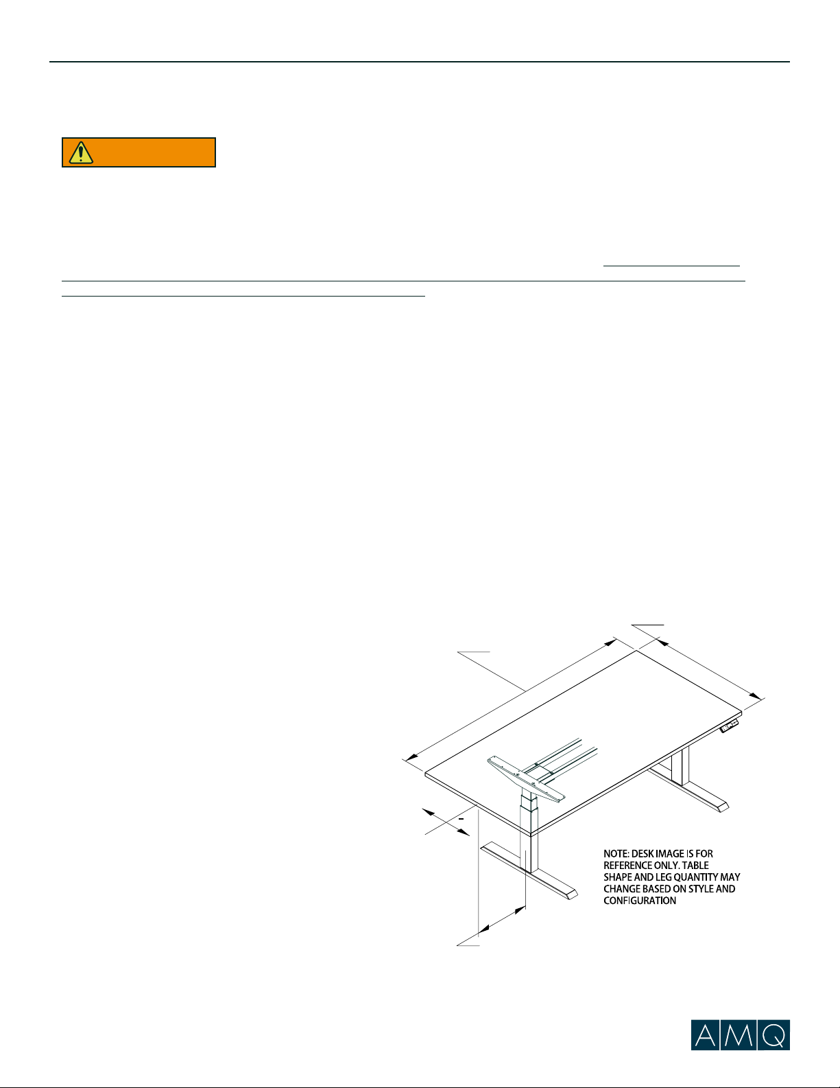
•MAINTAIN >1” (25mm) GAP ABOVE OBJECTS
ON DESK AT MAX HEIGHT AND BETWEEN
THE DESK & ADJACENT OBJECTS. Locate
desk, accessories, and nearby objects to
allow movement of desktop through full range without pulling cords, trapping body parts, or colliding with
anything (shelves, electrical plugs and cords, door knobs, window sills, storage cabinets, etc.)
• Always lock castors during use to keep adequate clearance between desk and other objects.
Risk of Tip-Over Injury. Before moving on castors:
1. Adjust desk to lowest height.
2. Verify path is clear of obstructions.
3. Remove objects not attached to desk.
4. Restrict monitor arms from moving outside desk perimeter.
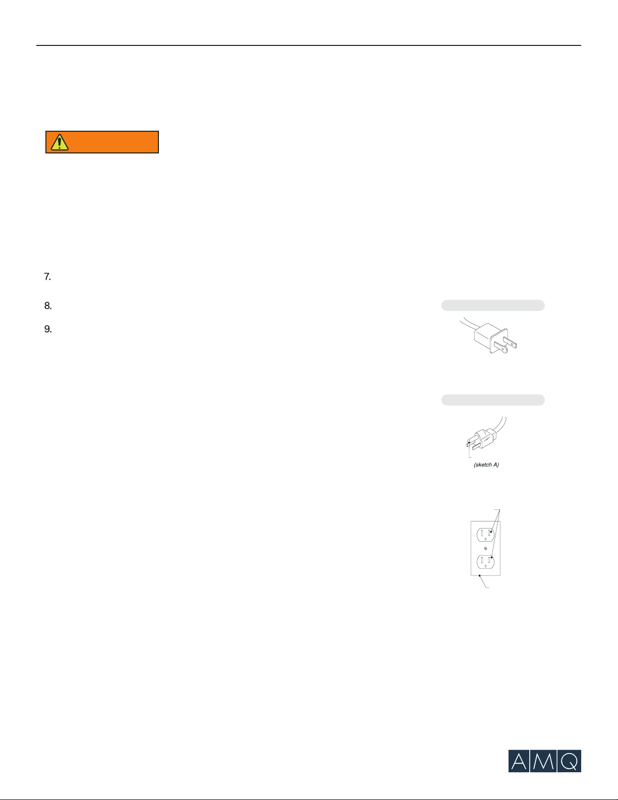
This device complies with part 15 of the FCC rules. Operation is subject to the following two conditions: (1) This device may not cause
harmful interference, and (2) this device must accept any interference received, including interference that may cause undesired operation.
This equipment has been tested and found to comply with the limits for a class B digital device pursuant to Part 15 for FCC rules. These limits
are designed to provide reasonable protection against harmful interference in a residential installation. This equipment generates, uses
and can radiate radio frequency energy and, if not installed and used in accordance with the instructions, may cause harmful interference
to radio communications. However, there is no guarantee that interference will not occur in a particular installation. If this equipment does
cause harmful interference to radio or television reception, which can be determined by turning the equipment off and on, the user is
encouraged to try to correct the interference by one or more of the following measures: Reorient or relocate the receiving antenna. Increase
the separation between the equipment and receiver. Connect the equipment into an outlet or a circuit different from that to which the
receiver is connected. Consult the dealer or an experienced radio/TV technician for help.
Important: Changes or modifications to this product not authorized by AMQ could void your authority to operate the product.
Max.
Min.
>1"
(25mm)
>1"
(25mm)
>1"
(25mm)
X
X
X
NOTE: Desk image
is for reference only.
Table shape and leg
quantity may change
based on the style
and configuration.
(877) 801-0307
www.amqsolutions.com
?
WARNING

Activ-Pro Assembly Guide | 4 amqsolutions.com
RISK OF SERIOUS INJURY:
POTENTIAL FOR INJURY: The use of worksurfaces that do not comply with the AMQ defined criteria and limitations
could cause personal injury or property damage due to pinch points, instability, or other problems.
POTENTIAL FOR NON-COMPLIANCE: The use of work surfaces that do not comply with AMQ criteria VOIDS any AMQ
claims of compliance with ANSI/BIFMA, UL, LEED, or other applicable requirements. The use of non-AMQ work surfaces
on AMQ adjustable-height bases may NOT be accepted as compliant to municipal electrical codes or OSHA federal
workplace standards, because this use does not create an NRTL (UL, ETL, etc.) listed product. AMQ is not responsible
for the ultimate determinations of compliance for height-adjustable bases with non-AMQ work surfaces.AMO assumes
NO liability for lack of standards compliance in these instances.
WARRANTY RESTRICTIONS: The use of non-AMQ supplied work surfaces VOIDS all AMQ warranties, expressed or
implied.
DISCLAIMER: The use of non-AMQ work surfaces is NOT recommended. Any use of a non-AMQ work surface requires
additional investigation by the customer regarding the appropriateness for use. It is the sole responsibility of the
customer to determine the suitability and safety of the selected work surface construction and attachment means.
The following information is provided as a guideline, but does not address all potential issues. Customers should seek
professional guidance as to the appropriateness of their chosen work surface.
MANDATORY REQUIREMENTS REGARDLESS OF WORK SURFACE MATERIAL OR CONSTRUCTION:
FASTENERS: Adjustable-height bases include fasteners intended for use with AMQ work surfaces.
These fasteners may potentially also be suitable for work surfaces meeting the following criteria:
• Medium-density or higher particleboard or fiberboard cores with High-pressure laminate (HPL), Lowpressure
laminate (LPL) or veneer & backers
• Thickness of .984” (25.0 mm) or greater
• Fasteners located a minimum distance of .984” (25.0 mm) from any edge
Any other work surface construction will require different and/or additional fastening means and these means must be
determined by the project’s designer, architect, or engineer. For example, solid-surface materials should use appropriate
threaded inserts and corresponding fasteners or similar attachment means.
In all cases, all fastener locations provided in the base
attachment features MUST be used (e.g. if attachment
plate has 6 screw holes, all 6 holes must be used for
attachment).
FLAMMABILITY: Any worksurface or similar large part>
10ft” 2 must have a flame spread< 200 and a smoke
developed index < 450 when tested per UL 723.
SHARP EDGES: All accessible edges of the work surface
must meet 1439 test for sharp edges.
DIMENSIONAL LIMITATIONS:
• Work surface depth not to exceed 30”(762mm)
• Longitudinal work surface position on base must be
on centerline
• Maximum work surface width may not exceed 72”
(1828.8 mm)
• Work surface overhang (distance from side of
support cantilever to edge of work surface) must be
greater than .75” (19mm) and may not exceed 1.25”
(32 mm)
FOLLOW ALL WARNINGS PROVIDED FOR BASE+ WORK
SURFACE.
WORKSURFACE
OVERHANG
C
L
+
WORKSURFACE
WIDTH
WORKSURFACE
DEPTH
Safety Statement
WARNING

Activ-Pro Assembly Guide | amqsolutions.com
Components
M6*8
x 8 M10*30
x 8 ST 5*18
x 2 ST 5*20
x 18
8mm 5mm
Allen keys
4mm Screw caps x 8
Hardware
Leg columns x 2
Stretcher bar assembly
with control box
Cantilevers*x 2 Cantilevers*x 2
Foot*x 2
Controller cable x 1
Power cable x 1
LED control
handset x 1
*Feet and cantilevers are boxed separately.
Foot*x 2
T - Type C - Type
M6*10
x 8 Cable
Management
Clip
Electrical rating: 120V, 60HZ, 4A. 2 stage desk model # ACTVDESKS2, 3 stage desk model #
ACTVDESK3, 2 stage base model # ACTVBASES2, 3 stage base model # ACTVBASES3.
Optional
Castor with brake
x 4

Activ-Pro Assembly Guide | 6 amqsolutions.com
Phase 1 | Preparing for Assembly
Step 1
Place Stretcher Bar unit upside down on work area.
Turn Stretcher Bar upside down
The label will face up when Stretcher Bar is
upside down and ready to begin assembly.

Activ-Pro Assembly Guide | 7 amqsolutions.com
Phase 2 | Attaching Legs
Step 1
Slide leg columns into place and attach with M6
screws. Match inside holes first and lightly tighten
at this point.
Match inside holes first and
lightly tighten at this point.
5mm
(4)
M6*8

amqsolutions.comActiv-Pro Assembly Guide | 8
Use screw
caps
Phase 3 | Attaching Cantilevers
Step 1
Insert Cantilevers on each end, lifting the leg
a bit, if needed, to ease into a flush fit. Tab
into place (fit is snug).
Step 2
Using M6 screws, tighten all 4 holes lightly. Once
level, go back through and tighten each screw
completely. Place plastic caps over each screw.
5mm
(4)
M6*8

Activ-Pro Assembly Guide | 9 amqsolutions.com
Phase 4 | Feet Assembly
Step 1
Attach feet using M10 socket screws. Match all 4
holes first to confirm fit before tightening completely.
8mm
(8)
M10*30

Activ-Pro Assembly Guide | 10 amqsolutions.com
IMPORTANT NOTE: Work surface overhangs
larger than .964” (25.0mm) are not allowed on
widths < 64.0” (1625.6mm)
Phase 5 | Adjusting Base Width
Step 1
Adjust to desired width. Use #4 allen key to loosen
the factory-inserted screws if not already loose.
Step 3
Tighten pre-mounted inset screws.
Use 4mm allen key to
tighten pre-mounted
inset screws
Centered screw
bracket
3
1
2
4mm
(8)
M6*10
Step 2
Once at correct width – and ensuring that centered
screw brackets are aligned – tighten all M6*10 screws.

Activ-Pro Assembly Guide | 11 amqsolutions.com
Phase 6 | Worksurface Mounting
Step 1
To attach the worksurface, start by laying the
worksurface down on the floor with the top
down. Lay the base assembly upside down on
top of the worksurface.
Step 2
The wire of the Handset passes through the
Handset Hole, connected to the Control box.
Step 3
Double check to ensure that the base is properly
positioned on the underside of the worksurface,
and then attach with wood screws.
Note: The worksurface should be center aligned
with the cantiliver depth and should have equal
amount of overhang on each end. Wireless drill is
required for assembly.
(2)
ST5*18
Handset
for worksurface
T - Type Cantilever C - Type Cantilever
(18)
ST5*20
for worksurface
(18)
ST5*16
2
3
Handset
Hole
The wire of the Handset passes
through the Handset Hole, connected
to the Control box.

Activ-Pro Assembly Guide | 12 amqsolutions.com
Connect each plug according to the drawing.
Orient yourself to the table assembly by facing
as a user to identify the left and right motors
Power
Right
motor
Left motor
Handset
Right
motor
Left
motor
Handset
Power
Phase 7 | Connecting Handset and Power
Step 1
Make sure that the Left motor plugs into the M2
port, and the Right motor plugs into the M1 port.
Step 2
Connect power plug after the motors and handset
are connected properly.
Step 3
Reset the base by holding the down arrow
button until it reaches its lowest height.
Step 4
Attach the plastic cable management to
desired area to secure cables and wires.
Facing
Direction

Phase 8 | Replacing Glides with Castors (Optional)
Step 1
Adjust the desk to the lowest height and place
it on the level floor by flipping it over
approximately 90° (Handset facing up).
Step 2
Remove the Glides.
Note: It is recommended to operate on a level
floor with carpets. And when flipping the table,
2 people need to operate at the same time.
Activ-Pro Assembly Guide | 13 amqsolutions.com

Step 3
Use a number 12 open wrench(not provided by
AMQ) to secure the castors.
Not provided
by AMQ
Step 4
When the castor installation is complete, the
castor needs to be locked. It need 2 people
to operate it at the same time to turn the
desk to its upright position.
Number 12
open wrench
3
Locking Caster
4
Phase 8 | Replacing Glides with Castors (Optional)
12mm
Activ-Pro Assembly Guide | 14 amqsolutions.com
Note: Casters are not offered for C-legs base or desk.

Activ-Pro Assembly Guide | 15 amqsolutions.com
Phase 9 | Program Height Memory Presets
Step 1
To Program Up to 4 Presets: Use the up/down
arrows to find desired height, then press “M”
followed by the number 1, 2, 3 or 4.
Step 2
To Test Programmed Height: Use the up/down
arrows to adjust the table to a height other than
the preset height. Then push the number you
programmed to see if it automatically adjusts to
the height programmed in Step 1. You may need
to hold for 2-3 seconds to activate the base.
Note: If it does not adjust to the programmed
height, repeat Step 1 followed by Step 2.
A
M
Q
1
2
3
M
4

missing any parts, have diculty with assembly,
or have any product related questions.
Other manuals for ACTIV
3
This manual suits for next models
1
Table of contents
Other AMQ Indoor Furnishing manuals
Popular Indoor Furnishing manuals by other brands

Jason.L
Jason.L Flexi premium Assembly instructions

feather&black
feather&black Loire Console Table Assembly instructions

QU-AX
QU-AX TRENDY 54 04 46-XL Series manual

PB TEEN
PB TEEN GENEVIEVE Assembly instructions

Simpli Home
Simpli Home Santiago AXCPTCON4-SAN Assembly instruction

Twin Star Home
Twin Star Home 42WM9991 manual

Black Box
Black Box 42U Brochure & specs

HOMEDEPOT
HOMEDEPOT WF283081AAB Assembly instructions

HAMPTON BAY
HAMPTON BAY Mansford Park PH20TL4S Use and care guide

PB TEEN
PB TEEN OOH-LA-LA Assembly instructions

HIGH ONE
HIGH ONE HM-ST013-001 Assembly instructions

Happy Beds
Happy Beds PodBed High Sleeper Assembly instructions