RISK OF SERIOUS INJURY :
POTENTIAL FOR INJURY:
The use of worksurfaces that do not comply with the AMQ defined criteria and limitations
could cause personal injury or property damage due to pinch points, instability, or other problems.
.
POTENTIAL FOR NON-COMPLIANCE:
The use of worksurfaces that do not comply with AMQ criteria VOIDS any
AMQ claims of compliance with ANSI/BIFMA, UL, LEED, or other applicable requirements. The use of non-AMQ
worksurfaces on AMQ adjustable-height bases may NOT be accepted as compliant to municipal electrical codes or
OSHA federal workplace standards, because this use does not create an NRTL (UL, ETL, etc.) listed product. AMQ is
not responsible for the ultimate determinations of compliance for height-adjustable bases with non-AMQ
worksurfaces. AMQ assumes NO liability for lack of standards compliance in these instances.
WARRANTY RESTRICTIONS:
The use of non-AMQ supplied worksurfaces VOIDS all AMQ warranties, expressed or
implied.
DISCLAIMER:
The use of non-AMQ worksurfaces is NOT recommended. Any use of a non-AMQ worksurface
requires additional investigation by the customer regarding the appropriate use. It is the sole responsibility of
the customer to determine the suitability and safety of the selected worksurface construction and attachment means.
The following information is provided as a guideline, but does not address all potential issues. Customers should seek
professional guidance as to the appropriateness of their chosen worksurface.
MANDATORY REQUIREMENTS REGARDLESS OF WORKSURFACE MATERIAL OR CONSTRUCTION:
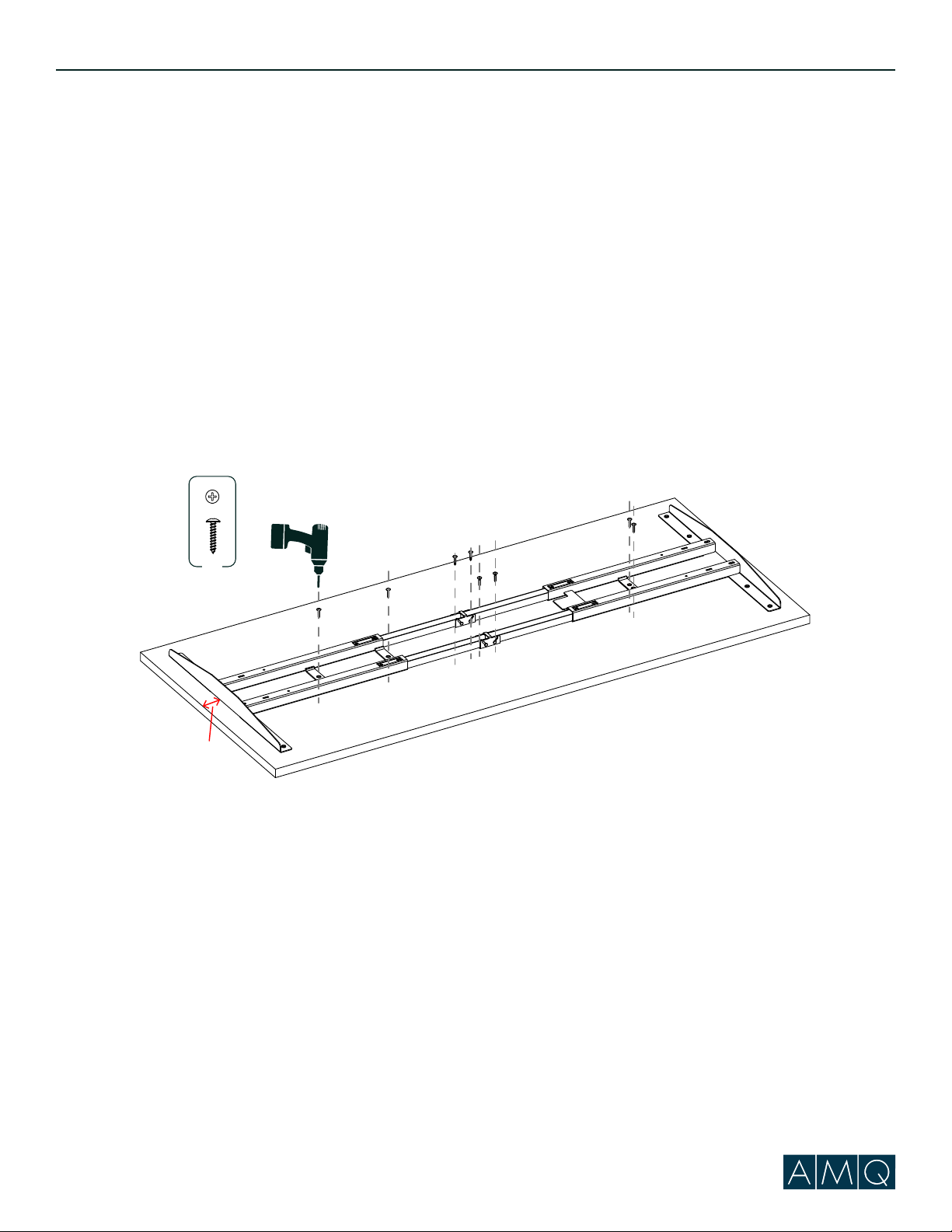
FASTENERS:
Adjustable-height bases include fasteners intended for use with AMQ worksurfaces.
These fasteners may potentially also be suitable for worksurfaces meeting the following criteria:
•Medium-density or higher particleboard or fiberboard cores with High-pressure laminate (HPL), Low-pressure
laminate (LPL) or veneer & backers
•Thickness of .984” (25 mm) or greater
•Fasteners located a minimum distance of .984” (25 mm) from any edge
Any other worksurface construction will require different and/or additional fastening means and these means must
be determined by the project’s designer, architect, or engineer. For example, solid-surface materials should use
appropriate threaded inserts and corresponding
fasteners or similar attachment means.
In all cases, all fastener locations provided in the
base attachment features MUST be used (e.g. if
attachment plate has 6 screw holes, all 6 holes
must be used for attachment).
FLAMMABILITY:
Any worksurface or similar large
part> 10ft” 2 must have a flame spread< 200
and a smoke developed index < 450 when tested
per UL 723.
SHARP EDGES:
All accessible edges of the
worksurface must meet UL 1439 test for sharp
edges.
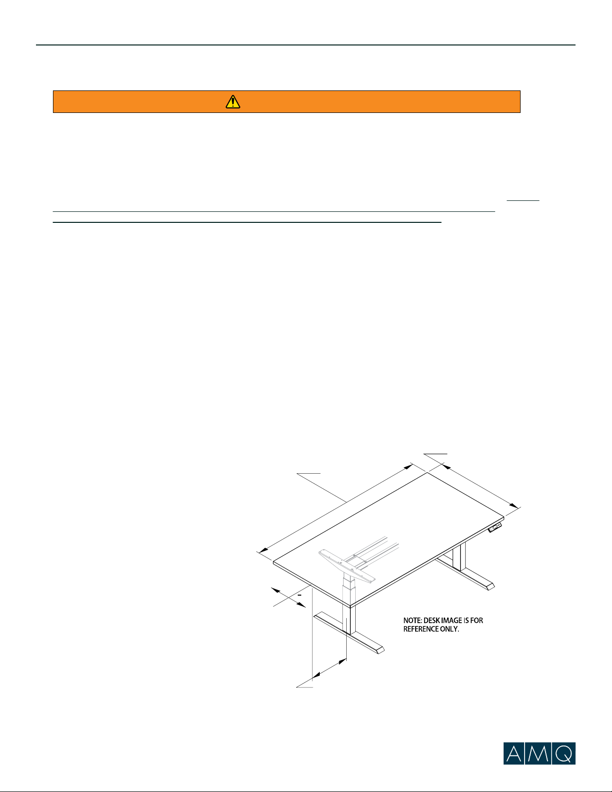
WORKSURFACE
OVERHANG
+
WORKSURFACE
WIDTH
WORKSURFACE
DEPTH
C
L
Safety Statement
amqsolutions.com
WARNING
DIMENSIONAL LIMITATIONS:
•Worksurface depth not to exceed
30” (762 mm)
•Longitudinal worksurface position on cantilever
must be on centerline +/- 1/8” (3.17 mm)
•Worksurface overhang (distance from side
of support cantilever to edge of worksurface)
must be 1"+/-1/16"
•Maximum worksurface width may not exceed 72” (1828 mm)
FOLLOW ALL WARNINGS PROVIDED FOR BASE AND WORKSURFACE.
Activ Pro 2.0 Assembly Guide | 5