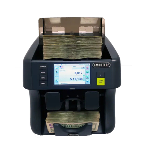
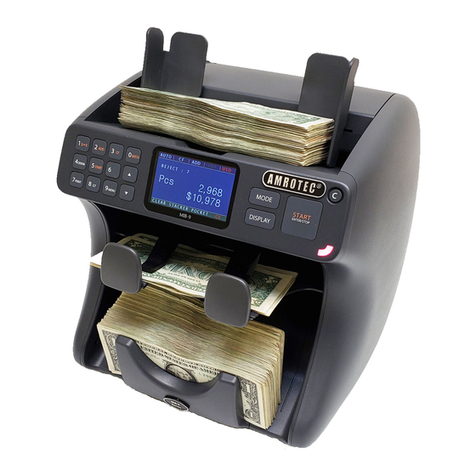
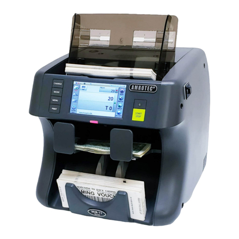
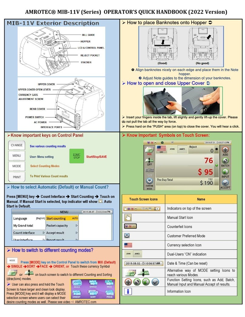
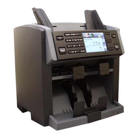
Amrotec MiB-9 User manual

1
MiB-9
Currency Discrimination Counter
2-Pocket and Multi-currencies counting

2
User Menu ----------------------------------------------------------------------------------------------
1. Language Set--------------------------------------------------------------------------
2. Counting Speed-----------------------------------------------------------------------
3. Pocket Capacity ----------------------------------------------------------------------
4. Setting -----------------------------------------------------------------------------------
1. Lock Menu ------------------------------------------------------------------------
2. Beep --------------------------------------------------------------------------------
3. Custom Display Setting ------------------------------------------------------
4. Auto Start --------------------------------------------------------------------------
5. LCD Control ----------------------------------------------------------------------
6. Display Set-------------------------------------------------------------------------
7. Select First View------------------------------------------------------------------
8. Dual User Set----------------------------------------------------------------------
5. PC Interface ----------------------------------------------------------------------------
1. Serial Set --------------------------------------------------------------------------
6. Sensitivity Setting--------------------------------------------------------------------
1. UV, MR, IR ------------------------------------------------------------------------
2. Double Level ---------------------------------------------------------------------
3. Hopper Level ---------------------------------------------------------------------
7. Parameter ------------------------------------------------------------------------------
1. Loading Default -----------------------------------------------------------------
2. Loading User --------------------------------------------------------------------
3. Saving User ----------------------------------------------------------------------
4. Print No. Clear -------------------------------------------------------------------
5. Date and Time Set --------------------------------------------------------------
6.
Station ID Set
--------------------------------------------------------------------
4
4
5
5
5
6
6
6
7
7
7
7
8
8
8-9
9
9
9
9
10
10
10
10
10
10
10
Service Menu 1----------------------------------------------------------------------------------------
7.1 How to enter Service Menu 1-----------------------------------------------------
7.2 Service Menu1-------------------------------------------------------------------------
1. Error Stop Ctrl. -------------------------------------------------------------------
2. Reject Detail On/OFF------------------------------------------------------------
3. System Report --------------------------------------------------------------------
4. Set A/S Call No.-------------------------------------------------------------------
5. Set Machine S/N ------------------------------------------------------------------
6. Calibration --------------------------------------------------------------------------
7. Sensor Select ---------------------------------------------------------------------
8. System Setting --------------------------------------------------------------------
Service Menu 2 ---------------------------------------------------------------------------------------
8.1 How to enter Service Menu 2---------------------------------------------------
8.2 Service Menu2 ----------------------------------------------------------------------
1.Sensor Test-----------------------------------------------------------------------
2. Key Test --------------------------------------------------------------------------
3. Motor Test
-------------------------------------------------------------------
----
11
11
11
12
12
13
13
13
13-14
14
14-15
16
16
16
17-18
18
18
CONTENTS

3
4. Selector Test -----------------------------------------------------------------------
5. Wing Speed Setting --------------------------------------------------------------
6. USB and SD Card Test ----------------------------------------------------------
Calibration --------------------------------------------------------------------------------------
9.1 CIS Calibration -------------------------------------------------------------------
9.2 IR Calibration ---------------------------------------------------------------------
9.3 UV Calibration --------------------------------------------------------------------
9.4 MR & Double Calibration -----------------------------------------------------
9.5 Hopper Calibration -------------------------------------------------------------
9.6 Solenoid Calibration -----------------------------------------------------------
19
19
19
20
20-21
22-23
24-25
26-27
28
29

4
User Menu
USER MENU
To set a function and its parameters, enter into USER MENU by pressing
MENU key on the Control Panel. The 'USER MENU' screen is shown in
exact at the right side.
Press UP/ DOWNkey to
move from one menu item to the next
followed by START/ENTER key on the right side of the Control panel to
confirm the selection. Or you can directly move from one menu item to the
next by pressing corresponding numeric key. For example, to move to
menu item “SETTINGS”, just press numeric “4” key and START/ENTER key to confirm the selection. To Exit from the menu
entirely, press CLEAR/ESC key or press MENU key again to toggle in between menu items using UP / DOWN key, press
MENU key again in sub menu mode. The factory default settings are like below;
Function/Parameter
Default Value
Speed 1000 NPM w/CF ON
Contrast of Note Normal
Beep On
Auto Start On
Mode Lock Off
Pocket Capacity Reject Pocket
100 notes
Stacker 200 Max
Interface
Baud 57600
Data 8
Stop 1
Parity None
1. LANGUAGE SET
From the USER MENU, operator can select their native language if
it is available on the sub-menu. Default is English language for
USA market.

5
2. COUNTING SPEED
From the USER MENU, operator can select the piece counting “SPEED” by pressing numeric 2 key or UP / DOWN key.
The machine offers five counting speed: 800 / 900 / 1000 / 1200 / 1500 NPM (Notes per Minute). In sub menu, press
corresponding numeric key or UP / DOWN key to select your desire speed confirmed by START/ENTER key. In COUNT mode,
you can set the speed up to 1500NPM maximum, but for all discriminating Modes, such as MIXED, SINGL or SORT modes,
machine speed is defaulted as 1000 (CF ON) or can be change to 1200 (CF Off). Please refer to the below table to see the
compulsory maximum speed for each condition.
Mode Compulsory Maximum Speed
COUNT 1500 NPM
MIXED / SINGL /
SORT / FACE /
ORENT
CF ON: 1000 NPM MAX (Default)
CF OFF: 1200NPM MAX
3. POCKET CAPACITY
The capacity of the Stacker and Reject Pocket can be selected using this SUB-menu by operator, mainly depends on the
condition of banknotes processed in a location. If a customer's location known to process good circulated banknotes, then the
capacity of the Stacker and Reject Pocket can be set to higher capacity, otherwise, it is suggested to use the default set value
by the factory as 200 Notes for Stacker and 100 Notes for
Reject Pocket. To select both pocket capacity, use () ()
key or corresponding numeric key followed by
START/ENTER key to confirm your selection.
4.
SETTING

6
1. LOCK MENU
To prevent accidental MODE switch, operator can disable
the MODE key function under LOCK MENU as MODE LOCK
(ON).
While MODE LOCK is (ON), the MODE key
becomes inactive. If operator wishes to change counting
MODE, it will first require deactivating the MODE LOCK
function to (OFF). To switch to ON/OFF, use
()()
key
or corresponding numeric key followed by START key to
confirm your selection.
To prevent accidental CF function shut off, operator can disable the CF key under LOCK MENU as CF LOCK
(ON).
While CF LOCK is (ON), the CF key becomes inactive. If operator wishes to disable this CF LOCK
feature, then it will first require disabling the CF LOCK function to (OFF) by using
()()
key or numeric
key followed by START/ENTER key to confirm your selection.
2. BEEP
There are two separate Beep function on this machine KEY
BEEP and WARNING BEEP and they are ON by default. “KEY”
Beep function represents beep sound when pressing Keys on the
control panel and if it is turned off, BEEP will not sound off. Same
for WARNING Beep feature which is turned on by Default.
Anytime there is a warning from machine operation, an audible
beep tone will sound off. To turn ON/OFF this function, enter into
their sub-menu item and use ()() key or numeric key followed by START/ENTER key to confirm your selection. It
is highly recommended that both Key and Warning beep should be turned ON all the time as it is also set as default in
the software.
3. CUSTOM DISPLAY SETTING:
Operator can select customer Display type on
this Menu item under 1. CUSTOMER DISPLAY
SETTING sub-menu. Operator can also select
whether count results on the external Customer
display should be stayed on until a next count
starts or clear out when banknotes are removed
from Stacker using 2.CUSTOMER DISPLAY CLEAR sub-menu.

7
4. AUTO START
When the AUTO function is turned ON, the machine automatically feeds
and counts banknotes on the hopper, whereas in MANUAL mode,
pressing START/ENTER key is required to start counting operation after
banknotes are placed into the hopper. Note that machine is defaulted as
"AUTO" from factory and to change into MANUAL mode, enter into “4.
AUTO START” sub-menu by pressing ENTER key or the numeric “4” key
and then make your selection / switch. If “AUTO START ON” is selected, the LCD screen will display “AUTO”,
otherwise will display “MAN.” Stands for “Manual” operation.
5. LCD CONTROL:
If the contrast of LCD screen found to be too dark or too
bright, operator can change the contrast level by using
()() key followed up START/ENTER key to confirm
the new setting. While default is set at 20 [0-30], the
higher >20 number would increase the contrast of the
LCD screen further which we do not highly recommend.
Under this LCD CONTROL menu, operator also has
option to keep LCD Display ON or turn OFF (to save power and LCD longevity) while machine is inactive.
6. DISPLAY SET
Operator can select 4 different screen views using of [DISPLAY] key and
appear w en a count is completed. Operator can press [DISPLAY] key to
c ange view to see SIMPLE VIEW 2 (Count and Pieces and Total count
and Pieces) or DETAIL VIEW (S owing Piece and total for all
denominations counted) or REJECT VIEW (to see reject reasons for all
rejected bills to reject pocket). (please refer to submenu “C anging
Display Contents” in Section. 6. Basic Operation)
7. SELECT FIRST VIEW
Operator can select and default
preferable view of t e main screen from 3
different screen views as illustrated on t e left side diagram. Operator can
use ()() key or corresponding numeric key to scroll and select your
selection by START/ENTER key, owever, in discriminating mode, it is
strongly suggested t at eit er 1. SIMPLE VIEW1 (Default) or ‘3.DETAIL
VIEW’ s ould be selected as t e main screen.

8
8. DUAL USER SET
DUAL-USER is a feature t at allows one MiB-9 mac ine to be s ared by two
operators as User1 and User2. T is feature is disable from factory by default,
t erefore if operator requires to activate t is feature, enter into t is Menu item
from USER MENU and make your selection as "DUAL USER ON" and to
deactivate, select “DUAL USER OFF".
DUAL USER OFF
W en t is feature is OFF as by factory default or by operator, mac ine
operates as for single user. In t is configuration, printer or PC is connected
to t e RS232C port and USB port is used to connect PC
(configuration is
subject to c ange wit out furt er notice).
DUAL USER ON
W en t is feature is turned ON, mac ine operates as for Dual Users. Eac user can connect t eir PCs to RS232C
port (User1’s PC) and USB A (User2’s PC) and sends counting results to corresponding PC. W ile bot users can
s are one printer, t ey ave to use different key to print w ic is, START/ENTER key (Rig t side of t e control panel)
for User1 and numeric ‘5’ (START) key on t e left side of t e control panel for User2 (See submenu “Dual User” in
Section. 6. Basic Operation).
5. PC Interface
Under PC Interface menu, operator is able to set Printer configuration (Baud Rate, Parity, Data Bit, Stop Bit), PC Protocol or
Customer display protocol as well as select AUTO PRINT options as described below:
1. SERIAL SET:
•AUTO PRINT: Operator can select to automatically print counting results
in a Printer (if one is connected) when after a count is completed and
hopper is empty out or auto-print per each batch count is completed or
operator can turned off this option to print manually after each count is
completed.
•For available printers, please consult with AMROTEC® or with
your sales representative.
•Standard “Serial” port configuration for printer is as below:
Speed (Baud Rate) : 9600 bps
Parity : None
Data Bit : 8
Stop Bit : 1
Printer Type : Type Normal (Default)

9
The parameters of an external Dot or Thermal printer should be set as above value. The Column Length
parameter is to be set to the column length of the printer. To print counting results, press START/ENTER key on
the right side of the Control panel for User1 and numeric ‘5’ (START) key on the left for User2 (See sub-menu
“Dual User” in Section. 6. Basic Operation).To print the Grand Total, press GT to display Grand Total and press
DISPLAY to see Grand Total Detail view.
2. SEL. OCR DATA PORT: This sub-menu option has no applicability for MIB-9 machine.
3. TCP/ IP TYPE: (Reserved for Software Developer)
4. IP Address: (Reserved for Software Developer)
5. MAC Address: (Reserved for Software Developer)
6. SDC100 PROTOCOL: (Reserved for Software Developer)
6.
Sensitivity Setting (Only for trained operator/service-provider)
This is a password protected area and reserved for highly trained operator or service-provider.
1.UV; 2.MR; 3.IR:
MIB-9 is equipped with number of suspect detectors such as UV (Ultra-Violet), MR (Magneto-resistive / MG) and
IR(Infra-red). Proper sensitivity settings
for these detectors are preset from
factory, however, if it becomes
necessary in case of a false alarm or
rejection of genuine banknotes due to
suspect errors, Operator is able to
readjust (lower) the factory preset
sensitivity settings (from 00 - 05) for
these detectors equipped with this machine. Lower Value sensitivity level refers to lower sensitivity of each of these
detectors. To determine the appropriate sensitivity level for each of these detectors, trained operator is recommended
to start settings from lower level to higher level for each of these detectors and one detector at a time.
To change the sensitivity level, enter into “6.SENSITIVITY SETTING” followed by ENTER and numeric key to scroll
through different detector sub-menu and choose the level by using ()() key. To confirm your selection, press
START/ENTER key and exit from the menu by pressing [C].
2. DOUBLE LEVEL: MIB-9 is equipped with a double detection sensor to prevent 2 banknotes to pass through
as one. Appropriate Double sensitivity level as 10 [00-20] has been adjusted from factory, however, if it is
necessary to trouble shoot double note error, trained operator or service-provide able to make slight adjustment of this
level around default value. Please note that any value over 10 may lead to single banknote is rejected as double note.
3.HOPPER LEVEL: MIB-9 is equipped with hopper sensor to detect presence of a banknote, thus machine starts
counting operation. Appropriate Hopper sensitivity level as 200 [100-300] has been adjusted from factory, however, if
it is necessary to trouble shoot a problem related with banknote presence, trained operator or service provider able to
make slight adjustment of this level around default value. Please note that any value over 200 may lead to machine’s
determination of a banknote presence on the hopper and machine may start to operate.

10
7.
Parameter
1. LOADING DEFAULT (only for trained professional)
Factory adjusted certain parameter (turned On/Off) and various settings as default settings during production. During
uses of MiB-9 machines in the field, operators or service-provider may change those parameters / settings to user’s
own preferences. "LOADING DEFAULT" function allows trained operators or service-provider to refresh all the
parameters and settings to factory's default settings.
2. LOADING USER
Operators have option to save their own settings and parameters by using of "SAVING USER" sub-menu as described
below under 3. SAVING USER and loading those setting and parameter by following "2. LOADING USER" sub-menu.
Operator can use ()() key or corresponding numeric key to enter into the sub-menu and START/ENTER key to
confirm the selection.
3. SAVING USER
Operators can save their own setting and parameters by following this sub-menu. To save operator’s own settings,
enter into “3. SAVING USER” followed by START/ENTER key to confirm selection. Operator to use ()() key or
corresponding numeric key to enter into the sub-menu.
4. PRINT NO. CLEAR
This function resets print sequence number to 001. Enter into and select “4. PRINT NO CLEAR” using ()() key or
corresponding numeric keys followed by START/ENTER key to confirm the selection.
5. DATE AND TIME SET
Operator can select or change date and time of counting operation that appears on each print report. Enter into and
select 5. DATE AND TIME SET by using ()() key followed by START/ENTER key. A new popup window will open
allowing input of date and time. Changes can be made by using of numeric keys (0-9) and scroll through by using of
UP() or DOWN() key. START/ENTER key must be pressed to confirm operator’s input and selection.
6. STATION ID SET
Station ID represents a given No. for each MiB-9 machine and would appear on each print report. Select “6.
STATION ID SET” to enter into this sub-menu and use numeric keys (1-9) to input your Station ID. Use ()
() key to scroll and START/ENTER key to confirm your input and save.
In case of DUAL USER operation, separate Station ID should be set for each operator as USER 1 and for USER 2
respectively (See submenu “Dual User” in Section. 4. Settings)

11
SERVICE MENU1
1.ERROR STOP CTRL.
REJECT DETAIL ON/OFF
SYSTEM REPORT
SET A/S CALL NO.
SET MACHINE S/N
CALIBRATION
SENSOR SELECT
SYSTEM SETTING
There are ‘Service Menu1’ and ‘Service Menu2.’
‘Service Menu1’ includes mainly the menu for adjusting Parameter of Sensors.
7-1.
How to enter ‘SERVICE MENU 1’
:
Press: 9→MODE→*****
To exit from the current function, press ‘9(menu)’ key and to move ‘SERVICE
MENU2’, press ‘DISPLAY’ key.
< Display of ‘SERVICE MENU 1’>
7-2. ‘
Service Menu1’
1. ERROR STOP CTRL. 1) ERROR STOP ON 2) ERROR STOP OFF
2. REJECT DETAIL ON/OFF 1) ON 2) OFF
3. SYSTEM REPORT 1) COUNTING REPORT 2) S/W VERSION
4. SET A/S CALL No.
5. SET MACHINE S/N 1) S/N DISPLAY 2) S/N SETTING
6. CALIBRATION 1) CIS 2) IR 3) UV 4) MR & DOUBLE
5) HOPPER 6) SOLENOID
7. SENSOR SELECT 1) UV 2) MR 3) IR
8. SYSTEM SETTING
1)
IMAGE DOWN SETTING
2)
REAL-TIME S/N PRINTING
3)
SAVE BMP TO USB
4)
USB SW LOCK DOWN LIST
5)
SAVE RP SENSOR LOG
6)
PROGRAM UPGRADE
7 SERVICE MENU 1

12
1.
ERROR STOP CTRL.
Sometimes there is need to prevent from
stopping the machine even though some error
is occurred when you test the machine. If you
want to do this, select “ERROR STOP OFF”.
But after the test, it must be restored to
“ERROR STOP ON”
2.
REJECT DETAIL ON/OFF
In case that the machine would reject Counterfeit
note, or damaged notes, you can check more
detail reject reason using this menu.
Machine will display reject reason including detail code.
ERROR STOP CTRL.
ERROR STOP ON
ERROR STOP OFF
REJECT DETAIL ON/OFF
1. ON
2. OFF
Summary of the REJECT REASONS
NO I.D. : The machine failed to identify the denomination.
-
NO ID (1) ~ NO ID (6): Asymmetrical Error
-
NO ID (7) ~ NO ID (10): IMAGE MATCHING ERROR
-
NO ID (12) ~ NO ID (13): IMAGE SACN
ERROR NO READ: The note was not
successfully read.
OVERRUN: The next note was fed too close to the first note.
CF: The note was suspected to be a counterfeit.
-
CF UV1: UV error in transmission
-
CF UV2: SUV error in transmission
-
CF UV3: UV error in reflection.
-
CF MR1: Can’t find MR signal (This area should have MR signal.)
-
CF MR2: Excessively detect MR signal (This area should not have MR signal.)
-
CF MR3: No difference between the area with MR signal and the area without
MR signal
-
CF IR1: Can’t find IR signal (This area should have IR signal.)
-
CF IR2: Excessively detect IR signal (This area should not have IR signal.)
-
CF IR3: No difference between the area with IR signal and the area without IR
signal
-
CF IR4~5: For Developer
STAY NOTE: Selected counting mode does not allow the note to down

13
3. SYSTEM REPORT
1)
Counting Report
In this mode, you can see the total
number of the counted notes and the
rejected notes.
2)
S/W version
You can check the version of S/W and Currency.
4.SET A/S CALL No.
After the machine is turned on, A/S call no. is displayed
on LCD. In this mode, you can set the telephone no. It is
available up to 20 characters by using Numeric Key and
then press START key to save it.
UP key - Back Space
DOWN key – Used as Right key
5.SET MACHINE S/N
6.CALIBRATION
1)
S/N Display
You can check the serial no. of the machine.
(In order that S/N is displayed correctly, S/N should be
input first in S/N Setting menu.)
2)
S/N Setting
You can input the serial no. of the machine. It is available up
to 20 characters by using Numeric Key.
UP key - Back Space
DOWN key – Used as Right key
In order that a system analyzes Reference
Level and a signal of the machine, the system
should know the full swing of a waveform of a
signal.
SYSTEM REPORT
COUNTING REPORT
S/W VERSION
A/S NO. SETTIMG
PRESS START TO SAVE
SET MACHINE S/N
S/N DISPLAY
S/N SETTING
CALIBRATION
CIS
IR
UV
MR & DOUBLE
HOPPER
SOLENOID

14
What is CALIBRATION?
CALIBRATION
is to make a full swing reference waveform to read the full level of a signal. If
the machine rejects too many notes, the system might not analyze the input of waveform.
It is possible to make a standard waveform for the system.
For more detail information,
please refer to the “9_CALIBRATION”
7.SENSOR SELECT
UV, MR, IR: If you want to turn on or off sensor,
you can do that in this mode.
Select menu by using UP/DOWN and change
ON/OFF by using START key
8.SYSTEM SETTING
a. IMAGE DOWN SETTING
You can designate the pocket for downloading
banknote image data and send the data to “Vol”
(special PC program which we provide) or “USB drive.”
(
For more detail information, please refer to the
“
Chapter10.Image data downloading
”)
i.IMAGE DOWN REJECT
: The banknote images from
rejected notes will be downloaded.
ii. IMAGE DOWN STACKER:
The banknote images from stacker (Lower pocket) will bedownloaded
iii. IMAGE DOWN ALL:
The banknote images from both upper and lower pockets will be downloaded
iv. STACKER MODE: Machine will count all notes to lower pocket only and they
will be downloaded
b. REAL-TIME S/N PRINTING
When you activate S/N (Serial number of Banknote)
printing function. You can print out S/N after
counting is done.
SENSOR SELECT
UV ON
MR ON
IR ON
IMAGE DOWN SETTING
1. IMAGE DOWN REJECT
2. IMAGE DOWN STACKER
3. IMAGE DOWN ALL
4. STACKER MODE
REAL-TIME S/N PRINTING
1. OFF
2. ON
SYSTEM SETTING
1. IMAGE DOWN SETTING
2. REAL-TIME S/N PRINTING
3. SAVE BMP TO USB
4. USB SW LOCK DOWN LIST
5. SAVE RP SENSOR LOG
6. PROGRAM UPGRADE

15
If you activate ‘
REAL-TIME S/N PRINTING’
on,
machine will start
printing during the machine on the counting
c. SAVE BMP TO USB
You can download banknote image data using USB drive.
For more detail information, please refer to the
“Chapter10. Image data Downloading”
d.
USB SW LOCK DOWN LIST
When your customer wants to increase the currency limit number, you can use special
solution named ‘CU kit (Currency upgrade Kit)’ using this menu.
For more detail information please contact our sales team.
e.
SAVE RP SENSOR LOG
Machine has 3 RP sensors.
You can get ‘Log Data’ using this menu.
After connecting ‘USB drive’ in the slot and
count money. RP sensor Log data will be saved.
f. PROGRAM UPGRADE
You can upgrade machine Software using this menu.
For more detail information, please refer to the
“Chapter12. Program update”
SAVE BMP TO USB
1. SAVE BMP ON
2. SAVE BMP OFF
SAVE RP SENSOR LOG
1. FUNCTION ON
2. FUNCTION OFF
PLEASE
INSERT
U S B

16
There are ‘Service Menu1’ and ‘Service Men2’ in Service Menu.
‘Service Menu2’ includes the menu to have a test for development or for repair.
8-1.
How to enter ‘SERVICE MENU 2’:
Press: 9(MENU)→MODE→***** →DISPLAY
To exit from the current function, press
‘9(menu)’ key. To move ‘SERVICE MENU1’,
press ‘MODE’ key.
< Display of ‘SERVICE MENU2’>
8-2. ‘
Service Menu2’
1. SENSOR TEST 1) LED TEST 1. HOPPER LED ON 3. SENSOR LED ON
2. HOPPER LED OFF 4. SENSOR LED OFF
2) HOPPER TEST
3) SENSOR LOGIC TEST
4) DOUBLE LOGIC TEST
2. KEY TEST
3. MOTOR TEST
1)
MAIN 1000 RPM ON 5) MAIN_FEED 1200 RPM
2)
MAIN 1200 RPM ON 6) MAIN_FEED 1500 RPM
3)
MAIN 1500 RPM ON 7) WING MOTOR ON
4)
MAIN_FEED 1000 RPM 8) MOTOR STOP
4. SELECTOR TEST
1)
SELECTOR STACKER
2)
SELECTOR REJECTOR
5. WING SPEED SETTING
1)
WING 800NPM 4) WING 1200NPM
2)
WING 900NPM 5) WING 1500NPM
3)
WING 1000NPM
6. USB AND SDCARD TEST
8 SERVICE MENU 2
SERVICE MENU2
SENSOR TEST
KEY TEST
MOTOR TEST
SELECTOR TEST
WING SPEED SETTING
USB AND SDCARD TEST

17
1.
SENSOR TEST
1)
LED TEST
Turn ON/OFF LED.
IR sensors such as JP, SP, Hopper, Reject and Stacker
sensors are invisible using human eyes. You can check these
lights using Phone camera.
2)
HOPPER TEST
In this mode, the level of HOPPER is
displayed. The machine will start counting
in below condition.
‘HOPPER OFF’ should lower than ‘32’ with banknote on the hopper.
3)
SENSOR LOGIC TEST
In this mode, you can check if the sensor is defective or not by checking detected logic status of
each sensor. The below pictures show logic status when the sensor is covered or open by note.
CASE LCD DISPLAY PICTURE
LEFT RIGHT
All doors are closed.
JP 0 0
SP
0
0
FRONT
0 REAR
0
0
REJECT F 0
STACKER 0
Upper Door is open.
LEFT RIGHT
JP 1 1
SP
0
0
FRONT
1 REAR
0
0
REJECT F 0
STACKER
0
Rear Door is open.
LEFT RIGHT
JP 0 0
SP
1
1
FRONT
0 REAR
0
1
REJECT F 0
STACKER 0
Front and Rear Door
LEFT RIGHT
are open.
JP 1 1
SP
1
1
FRONT
1 REAR
0
1
REJECT F 0
STACKER 0
SENSOR TEST
LED TEST
HOPPER TEST
SENSOR LOGIC TEST
DOUBLE LOGIC TEST
HOPPER ON : 250
HOPPER OFF : 25
DIFFERENCE : 225

18
Reject sensor is
LEFT RIGHT
covered
JP 0 0
SP
0
0
FRONT
0 REAR
0
0
REJECT F 1
STACKER 0
Stacker sensor is
LEFT
RIGHT
covered
JP 0 0
SP
0
0
FRONT
0 REAR
0
0
REJECT F 0
STACKER
1
4)
DOUBLE LOGIC TEST
With this menu, you can check the double level.
Before you select this mode, you need to check below:
Clean inside of the double sensors and the path of note.
Close the upper door and rear door well.
Please run the motor more than 5 sec.
Both left and right channel need to adjust ‘550’ (± 50).
2.
KEYTEST
In this mode, you can have a test if the machine
detects the input of key. Every time you press a key,
the name of the key will be displayed on LCD.
However, in case of CLEAR key, you exit from the
current menu in stead of displaying.
After you push the “start” button, and press 9(menu)
key, you can exit from the current menu.
3.
MOTOR TEST
You can run Main and(or) Feed Motor in various
speeds.
PRESS ANY KEY
MOTOR TEST
1.MAIN 1000 RPM ON
2. MAIN 1200 RPM ON
3. MAIN 1500 RPM ON
4. MAIN_FEED 1000 RPM ON
5. MAIN_FEED 1200 RPM ON
6. MAIN_FEED 1500 RPM ON
7. WING MOTOR ON
8. MOTOR STOP
DOUBLE TEST
CH LEFT : 550
CH RIGHT : 550

19
4.
SELECTOR TEST
1)
Selector Stacker
RED LED light (on the right of Front OPE) should be
turned on and the Guide Selector should move to
lower pocket (stacker) direction.
2)
Selector Rejecter
RED LED light (on the right of Front OPE) should be
turned off and the Guide Selector should move to
upper pocket(Rejector) direction.
5.
WING SPEED SETTING
The speed of Wing Stacker can change fast or slow
(“±10”) by pressing UP/DOWN key and press “START:
key to save it. (When the machine counting very poor-
quality banknotes, if it fly- out the bills, make it faster
than the default status)
To exit from current menu, press 9(menu) key.
6.
USB AND SD CARD TEST
You can test ‘USB’ and ‘SD card’ connections using this
menu. Insert ‘USB Drive’ and ‘Micro SD card’ in the slots
and select this menu.
Machine will show if the test result is succeeded or failed.
WING SPEED SETTING
1. WING 800NPM
2. WING 900NPM
3. WING 1000NPM
4. WING 1200NPM
3. WING 1500NPM
SELECTOR TEST
1. SELECTOR STACKER
2. SELECTOR REJECTOR
TEST USB AND SD CARD
USB test is succeeded
SDCARD test is failed

20
What is Calibration?
Calibration is to make a full swing reference waveform to read the full
level of a signal. If the machine rejects too many notes in Mixed Mode
or in CF Detection Mode, the system might not analyze the input of
waveform. It is possible to make a standard waveform for the system.
The below steps are necessary before doing Calibration.
1.
Load default parameter. (Press : 9(menu) →7→1 →C(Clear)
2.
Clean UV, MR, CIS and IR Sensors.
9-1. CIS CALIBRATION
If ‘MAIN PCB’ is replaced with a new one or there are lots of rejected notes from failure
of recognition (NO I.D) it is recommended to make a new CIS Calibration.
1.
Open upper cover then clean the sensors.
2.
Place the Calibration sheet on the surface of the CIS referring to the picture.
3.
Close the upper cover. Start CIS Calibration process.
CIS Calibration Sheet
9 CALIBRATION
CALIBRATION
CIS
IR
UV
MR & DOUBLE
HOPPER
SOLENOID
Other manuals for MiB-9
6
Table of contents
Other Amrotec Cash Counter manuals

Amrotec
Amrotec MIB-11F User manual

Amrotec
Amrotec MiB-9 User manual

Amrotec
Amrotec MiB-9 User manual

Amrotec
Amrotec MiB-11V Service manual

Amrotec
Amrotec MiB-11V User manual

Amrotec
Amrotec MiB-1 User manual

Amrotec
Amrotec MiB-11V User manual

Amrotec
Amrotec MiB-1 User manual

Amrotec
Amrotec X-1 Series User manual

Amrotec
Amrotec S-200 User manual
Popular Cash Counter manuals by other brands

Capetti Elettronica
Capetti Elettronica WineCap WSD12-2DI user manual

KISAN
KISAN NEWTON 3F operating instructions

Cassida
Cassida TillTally user manual

Fast Forward
Fast Forward EnergyCam Open Wire quick start guide

Royal Sovereign
Royal Sovereign RBC-100P owner's manual

Kübler
Kübler codix 130 operating instructions