ARB 3500720 User manual

Last Rev Date:
2
5
/0
6
/1
9
Page
1
of
1
4
Fitting instructions# 378
93
37
Copyright © 2019 by ARB Corporation Limited. All rights reserved, this document must not be reproduced without the express authority of ARB Corporation Ltd
Part Number:
3500720
, 3501000
Product
Description:
SUMMIT BAR
WINCH INSTALL KIT
Refer to Bull Bar fitting instructions for winch compatibility.
Winches may require additional fitting kits. Refer to table below for details.
WINCH MODEL
ADDITIONAL KITS
Zeon 8: W89965 WARN ZEON EXTENDED CABLE KIT
Zeon 8s: W89965 WARN ZEON EXTENDED CABLE KIT & 3500600 HAWSE FAIRLEAD ADAPTER KIT
Zeon 10: W89965 WARN ZEON EXTENDED CABLE KIT
Zeon 10s
Zeon 12:
W89965 WARN ZEON EXTENDED CABLE KIT & 3500600 HAWSE FAIRLEAD ADAPTER KIT
W89965 WARN ZEON EXTENDED CABLE KIT
Zeon 10 Platinum: W89965 WARN ZEON EXTENDED CABLE KIT
Zeon 10-s Platinum:
Zeon 12 Platinum:
W89965 WARN ZEON EXTENDED CABLE KIT & 3500600 HAWSE FAIRLEAD ADAPTER KIT
W89965 WARN ZEON EXTENDED CABLE KIT
XP: -
XPs: 3500600 HAWSE FAIRLEAD ADAPTER KIT
M8000: -
M8000s: 3500600 HAWSE FAIRLEAD ADAPTER KIT
XD9: -
XD9s: 3500600 HAWSE FAIRLEAD ADAPTER KIT
9.5XDC: 3500410 WARN XDC ADAPTER KIT
9.5XDC-s: 3500600 HAWSE FAIRLEAD ADAPTER KIT & 3500410 WARN XDC ADAPTER KIT
Magnum 8: -
Magnum 8s: 3500600 HAWSE FAIRLEAD ADAPTER KIT
Magnum 10:
-
Magnum 10s:
Magnum 12:
3500600
HAWSE FAIRLEAD ADAPTER KIT
-
Bushranger DV9TH: 3500780 BUSHRANGER CABLE COVER KIT
(OPTIONAL)
Bushranger Seal 9.5TH:
Bushranger DV12TH:
3500600 HAWSE FAIRLEAD ADAPTER KIT & 3500780 BUSHRANGER CABLE COVER KIT
(OPTIONAL)
3500780 BUSHRANGER CABLE COVER KIT (OPTIONAL)
Bushranger REVO 10W:
-
Bushranger REVO 10S: 3500600 HAWSE FAIRLEAD ADAPTER KIT
Smittybilt X20 10lbs cable: 3500770 SMITTYBILT ADAPTER KIT
Smittybilt X20 10lbs rope : 3500600 HAWSE FAIRLEAD ADAPTER KIT and 3500770 SMITTYBILT ADAPTER KIT
ARB 4x4 ACCESSORIES
Corporate Head Office
42-44 Garden St Tel: +61 (3) 9761 6622
Kilsyth, Victoria Fax: +61 (3) 9761 6807
AUSTRALIA 3137
www.arb.com.au

Last Rev Date:
2
5
/0
6
/1
9
Page
2
of
1
4
Fitting instructions# 378
93
37
Copyright © 2019 by ARB Corporation Limited. All rights reserved, this document must not be reproduced without the express authority of ARB Corporation Ltd
FITTING REQUIREMENTS
HAVE AVAILABLE THESE SAFETY ITEMS WHEN FITTING PRODUCT:
Protective eyewear
Hearing protection
NOTE: ‘WARNING’ notes in the fitting procedure relate to OHS situations, where to avoid a
potentially hazardous situation it is suggested that protective safety gear be worn or a safe work
procedure be employed. If these notes and warnings are not heeded, injury may result.
FASTENER TORQUE SETTINGS:
SIZE
Torque Nm
Torque lbft
M6 9Nm 7lbft
M8 22Nm 16lbft
M10 44Nm 32lbft
M12 77Nm 57lbft

Last Rev Date:
2
5
/0
6
/1
9
Page
3
of
1
4
Fitting instructions# 378
93
37
Copyright © 2019 by ARB Corporation Limited. All rights reserved, this document must not be reproduced without the express authority of ARB Corporation Ltd
PARTS LISTING
ITEM NO.
PART
NUMBER DESCRIPTION QTY.
1 3194775 PLATE CABLE GUARD SUMMIT BARS 1
2 3759464 NUMBER PLATE BRACKET LIFT UP 1
3 3759465 NUMBER PLATE BRACKET MOUNT 1
4 3759658 WARN CONTROL BOX BRACKET SUMMIT BARS 1
5 4581287 WASHER SPRING M6 x 2.5 x 1.6 BLACK ZINC 4
6 4584295 WASHER FLAT M6 X 12 X 1.3 BLACK ZINC 8
7 5848302 PACKER NYLON 2
8 6151074 BOLT UNC 3/8 X 1 ¾ 2
9 6151213 BOLT M6 x 1.0 x 20 8.8 BLACK ZINC 2
10 6151223 NUT NYLOC M6 x 1.0 BLACK ZINC 2
11 6151384 SCREW 5.2 X 16 BLACK ZINC 4
12 6151456 BOLT M10 x 1.5 x 45 ZINC 2
13 6151550 BOLT M6 x 1.0 x 25 PC8.8 BLACK ZINC 4
14 6151561 NUT FLANGE M6 x 1.0 BLACK ZINC 4
15 6250010 SPACER 17 X 12.6 X 10 4
16 6821189 NUMBER PLATE GROMMET 4
17 3789337 F/INST 3500720 3501000 WINCH INSTALL KIT SUMMIT
BAR (THIS DOCUMENT) 1
Last Rev Date:
2
5
/0
6
/1
9
Page
4
of
1
4
Fitting instructions# 378
93
37
Copyright © 2019 by ARB Corporation Limited. All rights reserved, this document must not be reproduced without the express authority of ARB Corporation Ltd
WINCH PREPA
RATION
This ARB bar has been designed to carry a variety of Warn, Magnum, Smittybilt and Bushranger
winches. Before the winch is fitted into the bar it will need to be configured for proper fit and operation.
Note: Before fitting the winch to the bar, ensure that you have read and understand the fitting
instructions supplied with the winch. These instructions only cover the fitment of the winch and
control box to the bar. They do not cover the wiring procedure. For this refer to the winch
manufacturer’s instructions.
You will need to modify your winch to allow fitment into the bar. See below for each of the winch brands:
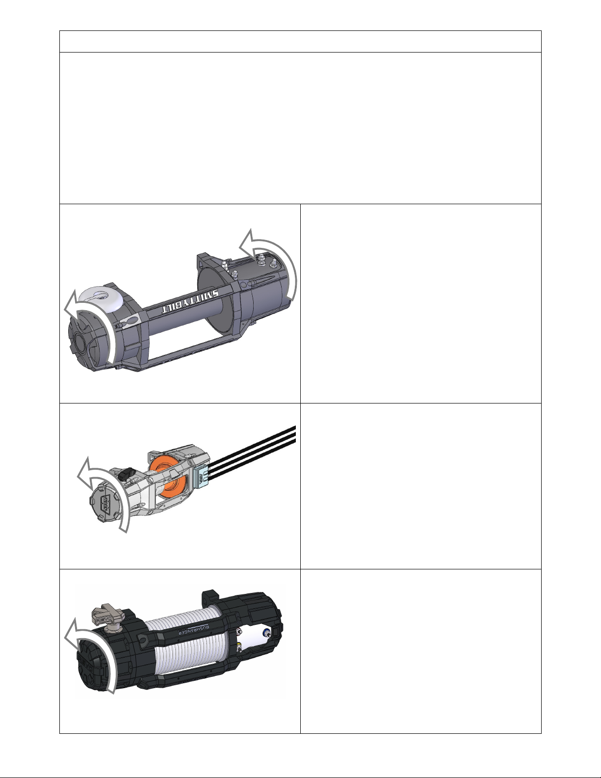
Note: The pictures below show the winches following modification.
Warn / Magnum / Smittybilt winches: Undo the
screws in the gearbox end of the winch. Carefully
slide the gearbox away from the winch only until it
is able to rotate. Rotate the gear box anti-clockwise
72° and replace screws.
Smittybilt winches only. Motor will need to be
rotated for adequate cable length. Remove 4 motor
retaining bolts and cover. Remove 2 additional
motor cap bolts. Rotate the motor until electrical
connections are facing upwards. Reinstall retaining
bolts and motor cover. (SMITTYBILT “GEN 2”
shown)
Ensure drain holes are correctly orientated. Refer
to winch instructions for more details.
Warn Zeon winches*: Undo the screws in the
gearbox end of the winch. Carefully slide the
gearbox away from the winch only until it is able to
rotate. Rotate the gear box anti-clockwise 72° and
replace screws.
Remove the control box as per the Zeon control
pack relocation kit installation guide.
Install the Warn Zeon relocation kit to the
winch and control box.
*Not required for Zeon Platinum models.
Bushranger winches: Undo the screws in the
gearbox end of the winch to remove the brake
cover. Remove the bolts retaining the gearbox
housing.
Rotate the gearbox anti-clockwise until the clutch is
as close as possible to directly upwards. Gearbox
rotation increments may be 36 °, 40° or 90°
depending on model. (“REVO 10” model shown)
Ensure fine seals are seated correctly then replate
and tighten all fasteners.
Ensure drain holes are correctly orientated
Refer to winch instructions for more details.

Last Rev Date:
2
5
/0
6
/1
9
Page
5
of
1
4
Fitting instructions# 378
93
37
Copyright © 2019 by ARB Corporation Limited. All rights reserved, this document must not be reproduced without the express authority of ARB Corporation Ltd
FITTING PROCEDURE
1. Lay the bar face down on a soft surface so as
not to damage the paint / powder coat.
2. If fitted, carefully remove the winch cover
plate and discard. Keep fasteners for re-use.
Warn Zeon / Platinum winches:
3. Mount the Control Box to the winch cradle
using 4x M6x25 hex head bolts, washers and
spacers provided with this kit.
4. Adjust the control box until it is approximately
5mm clear of front of control box recess and
tighten all fasteners.
M6 - 9 Nm.
5. Route and cable tie the Control Box Cables
clear of the winch spool area.
Control Box Assembled; Rear view shown
HINT:
Apply some split cable protection
conduit to the winch cables where they
pass through the Bull Bar.

Last Rev Date:
2
5
/0
6
/1
9
Page
6
of
1
4
Fitting instructions# 378
93
37
Copyright © 2019 by ARB Corporation Limited. All rights reserved, this document must not be reproduced without the express authority of ARB Corporation Ltd
FITTING PROCEDURE
Warn Magnum winches (“GEN 1”):
6. Remove top cover from winch by removing 3x
M4 bolts from side of plastic cover.
7. Undo 2x supplied M6 nuts from underside of
control box. To do so, top of M6 bolts located
on the inner side of the box will need to be
held in place.
8. Attach control box to control box bracket
using fasteners removed from control box in
earlier step, so that the top face of the bracket
is flush with the bottom surface of the control
box.
Do not fully tighten.

Last Rev Date:
2
5
/0
6
/1
9
Page
7
of
1
4
Fitting instructions# 378
93
37
Copyright © 2019 by ARB Corporation Limited. All rights reserved, this document must not be reproduced without the express authority of ARB Corporation Ltd
FITTING PROCEDURE
9. Secure plastic back onto control box, taking
care to leave the two supplied bolts in
position.
NOTE: ENSURE THE CUT-OUT EDGES OF THE
BRACKET FACE THE FRONT OF THE BAR AS
SHOWN
10. Mount the control box sub-assembly and
cable guard plate to the bar using the 4x
M6x25 bolts, flange nuts and washers
included in this kit. Rear view shown.
11. Adjust the control box until it is approximately
5mm clear of front of control box recess and
tighten all fasteners.
M6 - 9 Nm.
Control Box Assembled; Rear view shown
HINT:
Apply some split cable protection
conduit to the winch cables where they
pass through the Bull Bar then route and
cable tie them clear of the winch spool.

Last Rev Date:
2
5
/0
6
/1
9
Page
8
of
1
4
Fitting instructions# 378
93
37
Copyright © 2019 by ARB Corporation Limited. All rights reserved, this document must not be reproduced without the express authority of ARB Corporation Ltd
FITTING PROCEDURE
Warn Magnum winches (“GEN 2”):
12. Mount the Control Box to the Warn Mount
Plate using the fasteners supplied with the
winch kit, ensuring that the 2x centrally
located M6 hex head bolts pass through the
plates as shown.
13. Adjust the control box until it is approximately
5mm clear of front of control box recess and
tighten all fasteners.
M6 - 9 Nm.
14. Route and cable tie the Control Box Cables
clear of the winch spool area.
Control Box Assembled; Rear view shown
Warn M8000, XD9 & 9.5XP “Contactor” control
box winches.
15. Mount the control box to the 3759658 bracket
in this kit using 2x M6 flange nuts provided,
passing the control box cables past the cut-
out at the rear of the bracket. Rear view
shown.
NOTE: ENSURE THE CUT-OUT EDGES OF THE
BRACKET FACE THE REAR OF THE BAR AS
SHOWN
16. Mount the control box sub-assembly and
cable guard plate to the bar using the 4x
M6x25 bolts, flange nuts and washers
included in this kit.
HINT:
Apply some split cable protection
conduit to the winch cables where they
pass through the Bull Bar then route and
cable tie them clear of the winch spool.

Last Rev Date:
2
5
/0
6
/1
9
Page
9
of
1
4
Fitting instructions# 378
93
37
Copyright © 2019 by ARB Corporation Limited. All rights reserved, this document must not be reproduced without the express authority of ARB Corporation Ltd
17. Adjust the control box until it is approximately
5mm clear of front of control box recess and
tighten all fasteners.
M6 - 9 Nm.
Control Box Assembled; Rear view shown
Smittybilt “GEN 2” winches. Requires Smittybilt
adapter kit 3500770
18. Mount the Control Box to the adapter bracket
included in the 3500770 kit using the M5
hardware provided in the kit.
19. Mount the control box to the 3759658 bracket
in this kit using 2x M6x25 bolts, flange nuts
and washers removed in Step 2, passing the
control box cables past the cut-out at the rear
of the bracket. Rear view shown.
NOTE: ENSURE THE CUT-OUT EDGES OF THE
BRACKET FACE THE REAR OF THE BAR AS
SHOWN
20. Mount the control box sub-assembly and
cable guard plate to the bar using the 4x
M6x25 bolts, flange nuts and washers
included in this kit. Rear view shown.
HINT:
Apply some split cable protection
conduit to the winch cables where they
pass through the Bull Bar then route and
cable tie them clear of the winch spool.

Last Rev Date:
2
5
/0
6
/1
9
Page
10
of
1
4
Fitting instructions# 378
93
37
Copyright © 2019 by ARB Corporation Limited. All rights reserved, this document must not be reproduced without the express authority of ARB Corporation Ltd
21. Adjust the control box until it is approximately
5mm clear of front of control box recess and
tighten all fasteners.
M6 - 9 Nm.
Control Box Assembled; Rear view shown
Bushranger winches “GEN 1”.
22. First remove one plastic end from the control
box. Slide in two Hex head M8x20 bolts. (not
provided).
23. Replace plastic end of the control box and
fasten to bullbar using 2x M8 nut and washer
sets (not provided)
24. If desired optional cover kit 3500780 can be
fitted to back of bushranger control box.
M8 - 22 Nm.
25. Mount the cable guard plate to the bar using
2x M6x25 bolts, flange nuts and washers
included in this kit. Rear view shown.
26. Adjust the control box until it is approximately
5mm clear of front of control box recess and
tighten all fasteners.
M6 - 9 Nm.
Control Box Assembled; Rear view shown
HINT:
Apply some split cable protection
conduit to the winch cables where they
pass through the Bull Bar then route and
cable tie them clear of the winch spool.
HINT:
Apply some split cable protection
conduit to the winch cables where they
pass through the Bull Bar then route and
cable tie them clear of the winch spool.

Last Rev Date:
2
5
/0
6
/1
9
Page
11
of
1
4
Fitting instructions# 378
93
37
Copyright © 2019 by ARB Corporation Limited. All rights reserved, this document must not be reproduced without the express authority of ARB Corporation Ltd
Bushranger REVO winches “GEN 2”.
27. First remove the plastic control box cover
then align the two slots in the base with the
slots in the bar mount. Use at least 2x hex
head M8x20 bolts, washers and nuts to
secure the control box (not provided).
28. Carefully replace the plastic control box cover
and adjust the control box until it is
approximately 5mm clear of front of control
box recess and tighten the M8 fasteners.
M8 - 22 Nm.
29. Mount the cable guard plate to the bar using
2x M6x25 bolts, flange nuts and washers
included in this kit. Rear view shown.
M6 - 9 Nm.
Control Box Assembled; Rear view shown
HINT:
Apply some split cable protection
conduit to the winch cables where they
pass through the Bull Bar then route and
cable tie them clear of the winch spool.

Last Rev Date:
2
5
/0
6
/1
9
Page
12
of
1
4
Fitting instructions# 378
93
37
Copyright © 2019 by ARB Corporation Limited. All rights reserved, this document must not be reproduced without the express authority of ARB Corporation Ltd
Warn XDC control box winches: Requires XDC
adapter kit 3500410.
30. Mount the XDC Control Box to the adapter
bracket included in the 3500410 kit using the
M8 hardware provided in the kit. Note: the
control box cover will need to be removed
and rotated 180 degrees and re-assembled to
the bracket. Rear view shown.
M8 - 22 Nm.
31. Mount the control box to the 3750486 bracket
using the M6 fasteners supplied with the
3500410 kit, passing the control box cables
past the cut-out at the rear of the bracket.
32. Mount the control box sub-assembly and
cable guard plate to the bar using the 4x
M6x25 bolts, flange nuts and washers
included in this kit.
33. Adjust the control box until it is approximately
5mm clear of front of control box recess and
tighten all fasteners.
M6 - 9 Nm.
Control Box Assembled; Rear view shown
HINT:
Apply some split cable protection
conduit to the winch cables where they
pass through the Bull Bar then route and
cable tie them clear of the winch spool.

Last Rev Date:
2
5
/0
6
/1
9
Page
13
of
1
4
Fitting instructions# 378
93
37
Copyright © 2019 by ARB Corporation Limited. All rights reserved, this document must not be reproduced without the express authority of ARB Corporation Ltd
FITTING PROCEDURE
34. Sit the winch in position on the bar’s winch
cradle.
35. Attach the winch to the bar through the top 2
holes using 2 of the bolts (and any washers)
that are supplied with the winch.
36. Level the winch and tighten the bolts.
37. If not already done, mark 2 hole positions
25mm below the centre holes as shown in the
diagram.
38. Drill 2, Ø13mm holes. De-burr the holes and
protect with a zinc rich primer to prevent rust.
Note: Hawse fairleads require kit 3500600
Refer to Hawse fitting kit instructions.
39. Turn the bar over onto the back face.
40. Attach the roller fair lead (RFL) to the bar and
winch using the longer hex bolts supplied in
this kit and any washers supplied with the
winch.
Note 1: To make it easier to get to the bolt
holes in the RFL, remove the vertical roller pins
and rollers.
Note 2: Some winches will require 3/8” UNC
bolts where others will require M10. Both have
been supplied in this kit. Please check the
threads before proceeding. This can be done
by comparing the bolts from this kit with the
ones supplied with the winch.
M10- 44 Nm. 3/8th - 44 Nm.
Warning: Drill
ing operations
can result in flying metal
debris, safety glasses should
be worn.

Last Rev Date:
2
5
/0
6
/1
9
Page
14
of
1
4
Fitting instructions# 378
93
37
Copyright © 2019 by ARB Corporation Limited. All rights reserved, this document must not be reproduced without the express authority of ARB Corporation Ltd
FITTING PROCEDURE
41. Assemble the 2 folding number plate mount brackets together using the M8 hex bolts, Washers,
Packers and Nyloc Nuts as shown in the diagram below.
42. Assemble the bracket assembly to the bar using the fasteners supplied with the bar fitting kit.
Follow the step in the bars fitting instructions showing the fixed license plate bracket being mounted
substituting the folding assembly for the fixed.
M6 – 9 Nm
43. Ensure all cables are attached as per the winch manufacturer’s instructions. Ensure cables are
securely attached and cannot rub on any sharp edges.
44. Tidy the cables and secure using cable ties leaving the 2 long power cables free to be connected to
the vehicles battery later.F
Return to the bar fitment instructions.
NOTE: TRIM HERE, BOTH
SIDES; IF FITTING A
SLIMLINE NUMBER PLATE
Warning: Drill
ing operations
can result in flying metal
debris, safety glasses should
be worn.
This manual suits for next models
1
Table of contents
Other ARB Automobile Accessories manuals

ARB
ARB AIR LOCKER RD135 User manual

ARB
ARB RD177 User manual

ARB
ARB AIRLOCKER RD188 User manual

ARB
ARB ESPERANCE 802200 User manual

ARB
ARB INTENSITY SOLIS User manual

ARB
ARB RD246 Product information sheet

ARB
ARB AIRLOCKER RD142 User manual

ARB
ARB 1780500 User manual

ARB
ARB LINX LX100 User manual

ARB
ARB 3432300 User manual


Popular Automobile Accessories manuals by other brands


ULTIMATE SPEED
ULTIMATE SPEED 279746 Assembly and Safety Advice

SSV Works
SSV Works DF-F65 manual

ULTIMATE SPEED
ULTIMATE SPEED CARBON Assembly and Safety Advice

Witter
Witter F174 Fitting instructions

WeatherTech
WeatherTech No-Drill installation instructions

TAUBENREUTHER
TAUBENREUTHER 1-336050 Installation instruction