manuals.online logo
Brands
  1. Home
  2. •
  3. Brands
  4. •
  5. Asco
  6. •
  7. Control Unit
  8. •
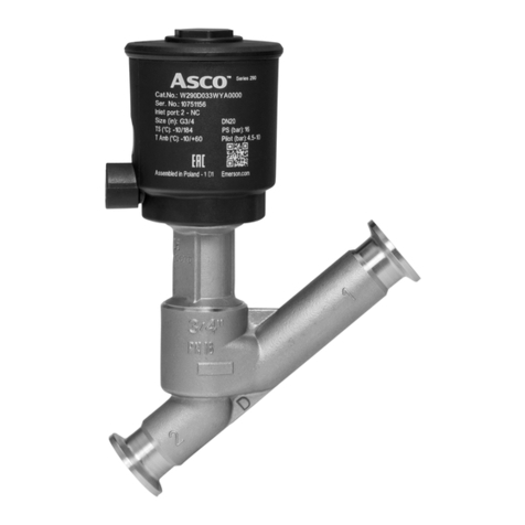
  9. Asco 290 Series User manual

Asco 290 Series User manual

Maintenance instructions
Instructions d'entretien
Wartungsanleitung
PROPORTIONAL 2/2 VALVES NC WITH PROFILED DISC, SERIES 290
CLAPET PROFILE VANNES PROPORTIONNELLES 2/2 NF, SERIE 290
2/2-PROPORTIONALVENTILE NC MIT PROFILTELLER, BAUREIHE 290
Series
Série
Baureihe
290
GB
FR
DE
GB INSTALLATION
Prior to all maintenance work or putting into operation, cut off the air
supply, depressurize the valve and vent it in order to prevent injury
to life or property.
1
.
As this valve is normally closed, air must be supplied to the pilot port in
order to unscrew the stuffing box.
2
. Remove the pilot operator and stuffing box with a wrench (a) or (c).
3. Loosen the profiled nut with the specific hook wrench (b), code C140098.
To prevent rotation, hold the disc in place, not the stem.
4. Clean all accessible parts.
5. Replace parts nos. 1 and 4 with the corresponding parts from the spare
parts kit.
6. Apply some threadlocker (Loctite 271) on the screw.
7.
Tighten the profiled nut with the hook wrench (b).
According to the version used, tighten the set screw to the torque (d).
8.
Reassemble the parts and observe the indicated tightening torques.
Make sure no foreign matter enters the valve and piping in the process.
!
Prior to putting the valve into operation, check for correct operation
of the valve in order to prevent injury to life or property. Also check for
possible internal or external leaks (seats) using a non-explosive and non-
inflammable fluid.
FR PROCEDURE DE DEMONTAGE / REMONTAGE
Avant toute opération d'entretien ou de remise en marche, couper
l'alimentation et dépressuriser, purger la vanne pour prévenir tout
risque d'accident corporel ou matériel.
1. Piloter la tête de commande (vannes NF) pour faciliter le dévissage du
presse-étoupe.
2. Dévisser l'ensemble tête de commande et presse-étoupe à l'aide d'une
clé (a) ou (c).
3. Dévisser l'écrou profilé avec la clé spécifique à ergots (b), code C140098.
Pour éviter toute rotation, maintenir le diamètre extérieur du clapet, jamais
le diamètre de tige.
4. Nettoyer toutes les parties rendues accessibles.
5. Remplacer les pièces repérées (1) et (4) avec le kit de pièces de rechange
correspondant.
6. Préencoller la vis avec le tube de colle frein-filet (Loctite 271).
7. Resserer l'écrou profilé avec la clé spécifique (b).
Selon les versions, resserrer la vis sans tête au couple (d).
8. Remonter les pièces en respectant les couples de serrage indiqués.
Veillez à ne pas introduire de corps étrangers dans la vanne et tuyauterie
pendant cette intervention.
!
Pour prévenir tout risque d'accident corporel ou matériel, vérifier que
la vanne fonctionne correctement avant de la remettre en service. Vérifier
aussi l'existence d'éventuelles fuites internes (sièges) ou externes avec un
fluide non-explosible et ininflammable.
DE MONTAGE-/DEMONTAGE-ANLEITUNG
Um Personen- und Sachschäden zu vermeiden, muss vor der Wartung oder
Inbetriebnahme die Versorgung desVorsteuerventils unterbrochen, das Ventil
drucklos geschaltet und entlüftet werden.
1. Beaufschlagen Sie den Steuerkopf des NC-Ventils mit Druck, um die
Stopfbuchse leichter demontieren zu können.
2. Demontieren Sie die Einheit aus Steuerkopf und Stopfbuchse mit einem
Schlüssel (a) oder (c).
3.
Schrauben Sie die Profilmutter mit dem speziellen Schlüssel ab (b) - Code
C140098. Um ein Verdrehen zu vermeiden, ist der Ventilteller und nicht die
Spindel festzuhalten.
4. Reinigen Sie alle zugänglichen Teile.
5.
Ersetzen Sie die Teile Nr. 1 und 4 mit den dafür vorgesehenen Ersatzteilen.
6. Schmieren Sie die Schraube (5) mit etwas Sicherungskleber aus der Tube
(Loctite 271) ein.
7. Ziehen Sie die Profilmutter mit dem Hakenschlüssel (b) fest.
Je nach Ausführung ist der Gewindestift mit dem Drehmoment (d) anzu-
ziehen.
8. Montieren Sie die Teile wieder und beachten Sie dabei das jeweils ange-
gebene Anziehdrehmoment.
Achten Sie darauf, dass bei diesem Vorgang keine Fremdkörper in das Ventil
und die Verrohrung gelangen.
!
Um Personen- und Sachschäden zu vermeiden, prüfen Sie vor der
Wiederinbetriebnahme die richtige Funktionsweise des Ventils. Prüfen Sie
das Ventil auch auf eventuelle Undichtigkeiten anhand eines nicht-explosi-
onsfähigen und nicht-zündfähigen Mediums.
2
3
TIGHTENING TORQUES and SPARE PARTS KIT
COUPLES DE SERRAGE et POCHETTE DE RECHANGE
ANZIEHDREHMOMENTE und ERSATZTEILPACKUNG
Valve - Vanne - Ventile ØDN (1)
(4)
N.m in.Lb (mm)
abcdabcdabc
• Compact
• Compacte
• Kompaktventil
1/2 15 C131201 12 3 - 2 105 26 - 17,5 27 8,5 -
3/4 20 C131202 12 3 - 2 105 26 - 17,5 27 8,5 -
125C131203 20 3 - 2 176 26 - 17,5 27 9,5 -
• Bronze, st.st, AISI 316L, clamp
couplings and butt welding stubs
• Bronze, inox, AISI 316L,
"CLAMP" et embouts à souder
• Bronze, Edelstahl, AISI 316L,
Clamp-Verbindung u. Anschweißenden
1/2 15 C131204 100 5 - 2 880 44 - 17,5 32 *8,5 -
3/4 20 C131205 100 5 - 2 880 44 - 17,5 36 *8,5 -
125C131206 120 5 - 2 1060 44 - 17,5 46 *9,5 -
1 1/4 32 C131207 120 5 - 2 1060 44 - 17,5 36 9,5 -
1 1/2 40 C131208 150 5 - 2 1320 44 - 17,5 46 13,5 -
260C131209 150 5 - 2 1320 44 - 17,5 46 13,5 -
2 1/2 65 C131622 200 5 - 2 1770 44 - 17,5 46 19,5 -
A
• Flanged with cast iron body
• Corps fonte à brides
• Flansch- mit Gehäuse aus Grauguss
-25C140013 - 5 20 2 - 44 175 17,5 - 9,5 13
-32C140014 - 5 30 2 - 44 262 17,5 - 9,5 17
-40C140015 - 5 30 2 - 44 262 17,5 - 13,5 17
-50C140016 - 5 30 2 - 44 262 17,5 - 13,5 17
B
• Flanged with bronze body
• Corps bronze à brides
• Flansch mit Gehäuse aus Bronze
-25C140017 120 5 - 2 1060 44 - 17,5 32 9,5 -
-32C140018 120 5 - 2 1060 44 - 17,5 36 9,5 -
-40C140019 150 5 - 2 1320 44 - 17,5 46 13,5 -
-50C140020 150 5 - 2 1320 44 - 17,5 46 13,5 -
• Disc seal (1), seal (4)
• Garniture clapet (1), joint (4)
• Tellerdichtung (1), Dichtung (4)
• Used only on standard disc
• Utilisé uniquement sur clapet standard
• Wird nur beim Ventiller verwendet
IM160-3-X-R2
3834629
*Ø 50 bronze/bronce/bronzo/bronzen : a = 30
a
bd
1
4
2 mm
DN 20, 25, 32,
40, 50, 65
DN 15
271
a
1
4
c
bd
2 mm
DN 32, 40, 50
DN 25
d
2 mm
271
E290 T290
AB
a
bd
1
4
2 mm
DN 20, 25, 32,
40, 50, 65
DN 15
271
a
1
4
c
bd
2 mm
DN 32, 40, 50
DN 25
d
2 mm
271
2
3
Instrucciones de mantenimiento
Istruzioni di manutenzione
Onderhoudsinstructies
CLAPET PERFILADO VÁLVULAS PROPORCIONALES 2/2 NC, SERIE 290
VALVOLE PROPORZIONALI 2/2 NC CON OTTURATORE PROFILATO, SERIE 290
PROPORTIONELE 2/2 AFSLUITERS (NC) MET PROFIELKLEP, SERIE 290
Serie
Series
Serie
290
ES
IT
NL
ES PROCEDIMIENTO DE DESMONTAJE / MONTAJE
Antes de cualquier operación de mantenimiento o de puesta en marcha,
corte la alimentación y despresurice, purgue la válvula para prevenir
todo riesgo de accidente corporal o material.
1. Pilote la cabeza de mando (válvulas NC) para facilitar el
desatornillado del prensa-estopas.
2. Desatornille el conjunto cabeza de mando y prensa-estopas con la ayuda
de una llave (a) o (c).
3. Desatornille la tuerca perfilada con la llave específica de patilla (b)
código C140098. Para evitar toda rotación, sujete el diámetro
exterior del clapet, nunca el diámetro del vástago.
4. Limpie todas las partes accesibles.
5. Reemplace las piezas refenciadas (1) y (4) con el kit de piezas de
recambio correspondiente.
6. Encole el tornillo con el trabado de roscas (Loctite 271).
7. Apriete la tuerca perfilada con la llave específica (b).
Según las versiones, apriete el tornillo sin cabeza al par (d).
8. Monte las piezas respetando los pares de apriete indicados.
Compruebe que no se ha introducido ningún cuerpo extraño en la válvula
y tubería durante esta intervención.
!
Para prevenir todo riesgo de accidente físico o material, verifique que
la válvula funciona correctamente antes de la puesta en marcha.
Verifique también la existencia de eventuales fugas internas (asientos)
o externas con un fluido no-explosivo e ininflamable.
IT INSTALLAZIONE
Prima di qualsiasi operazione di manutenzione o messa in funzione,
togliere l’alimentazione, depressurizzare le valvole per evitare danni
a persone o a cose.
1
.
Dato che la valvola è normalmente chiusa, è necessario pilotare la testa
di comando (valvola NC) per poter togliere il premistoppa.
2
. Rimuovere la testa di comando e il premistoppa con una chiave specifica
(a) o (c).
3. Svitare il dado profilato con una chiave specifica (b), codice C140098. Per
evitare qualsiasi rotazione, mantenere l’otturatore nella sede, non lo stelo.
4. Pulire le parti accessibili.
5. Rimontare le parti con rif. 1 e 4 con le parti corrispondenti dal kit delle
parti di ricambio.
6. Applicare del frenafiletti (Loctite 271) sulla vite.
7.
Serrare il dado profilato con una chiave specifica (b).
A seconda delle versioni, serrare la vite con relativa coppia di serraggio (d).
8.
Riassemblare le parti rispettando la coppia di serraggio indicata.
Assicurarsi che nessun materiale estraneo entri nella valvola e nelle
tubazioni di processo.
!
Prima di mettere le valvole in funzione, controllare il corretto funziona-
mento delle valvole per prevenire danni a persone o a cose. Controllare
inoltre per quanto possibile fughe (sedi) interne o esterne usando un fluido
non-esplosivo e non-infiammabile.
NL INSTALLATIE
Schakel voorafgaand aan alle onderhouds- en inbedrijfstellingswerk-
zaamheden de persluchttoevoer uit, laat de overdruk ontsnappen en
ontlucht de afsluiter om persoonlijk letsel en schade te voorkomen.
1
.
Omdat dit een normaal gesloten afsluiter is, moet u luchtdruk op de
stuurpoort zetten om de pakkingbus te kunnen losschroeven.
2
. Schroef de stuurkop en de pakkingbus los met behulp van een sleutel
(a) of (c).
3. Draai de profielmoer los met de speciale haaksleutel (b), code C140098.
Houd de klep vastgeklemd om meedraaien te voorkomen, nooit de spindel.
4. Reinig alle onderdelen grondig.
5. Vervang de onderdeelnrs. 1 en 4 met de overeenkomstige onderdelen uit
de reserveonderdelenset.
6. Breng op het schroefdraad een kleine hoeveelheid borgingsmiddel (Loc-
tite 271) aan.
7.
Draai de profielmoer met de speciale haaksleutel (b) vast.
Draai, afhankelijk van de versie, de stiftschroef weer met het juiste aan-
draaimoment (d) vast.
8.
Monteer alle onderdelen en draai ze met het juiste aandraaimoment vast.
Zorg dat er tijdens het onderhoud geen vuil in de afsluiter of leidingen
terechtkomt.
!
Controleer of de afsluiter correct werkt voordat u hem opnieuw in bedrijf
stelt, om zo elk risico op lichamelijk letsel of materiële schade uit te sluiten.
Controleer met behulp van een niet-explosieve en niet-ontvlambare vloeistof
• Se utiliza únicamente en discos estándar
• Utilizzata solo su disco standard
• Alleen voor standaardklep
PARES DE APRIETE y BOLSAS DE RECAMBIO
COPPIA DI SERRAGGIO E KIT PARTI DI RICAMBIO
AANDRAAIMOMENTEN en RESERVEONDERDELENSET
Válvula - Valvola - Afsluiter ØDN (1)
(4)
N.m in.Lb (mm)
abcdabcdabc
• compacta
• compatta
• Compacte
1/2 15 C131201 12 3 - 2 105 26 - 17,5 27 8,5 -
3/4 20 C131202 12 3 - 2 105 26 - 17,5 27 8,5 -
125C131203 20 3 - 2 176 26 - 17,5 27 9,5 -
• Bronce, inox, AISI 316L
"CLAMP" y de extremos para
soldar
• Bronzo, inox, AISI 316L,
"CLAMP" e attacchi a saldare
• Brons, roestvrij staal, AISI 316L,
met pijpdraad, met schroefdraad,
"CLAMP" en lasuiteinden
1/2 15 C131204 100 5 - 2 880 44 - 17,5 32 *8,5 -
3/4 20 C131205 100 5 - 2 880 44 - 17,5 36 *8,5 -
125C131206 120 5 - 2 1060 44 - 17,5 46 *9,5 -
1 1/4 32 C131207 120 5 - 2 1060 44 - 17,5 36 9,5 -
1 1/2 40 C131208 150 5 - 2 1320 44 - 17,5 46 13,5 -
260C131209 150 5 - 2 1320 44 - 17,5 46 13,5 -
2 1/2 65 C131622 200 5 - 2 1770 44 - 17,5 46 19,5 -
A
• Cuerpo fundición con bridas
• Corpo in ghisa flangiato
• Met flenzen en gietijzeren huis
-25C140013 - 5 20 2 - 44 175 17,5 - 9,5 13
-32C140014 - 5 30 2 - 44 262 17,5 - 9,5 17
-40C140015 - 5 30 2 - 44 262 17,5 - 13,5 17
-50C140016 - 5 30 2 - 44 262 17,5 - 13,5 17
B
• Cuerpo de bronce con bridas
• Corpo in bronzo flangiato
• Met flenzen en bronzen huis
-25C140017 120 5 - 2 1060 44 - 17,5 32 9,5 -
-32C140018 120 5 - 2 1060 44 - 17,5 36 9,5 -
-40C140019 150 5 - 2 1320 44 - 17,5 46 13,5 -
-50C140020 150 5 - 2 1320 44 - 17,5 46 13,5 -
E290 T290
*Ø 50 bronze/bronce/bronzo/Bronzen : a = 30
AB
2
• Guarnición clapet (1), junta (4)
• Tenuta dell’otturatore (1), tenuta (4)
• Klepafdichting (1), afdichting (4)
ASCO JOUCOMATIC SA
32 Av. Albert 1er - BP 312 - 92506 RUEIL Cedex - France
Tel. (33) 147.14.32.00 - Fax (33) 147.08.53.85 - http://www.asconumatics.eu
Other manuals for 290 Series

8

This manual suits for next models

2

Other Asco Control Unit manuals

Asco 290 Series User manual

Asco

Asco 290 Series User manual

Asco 8316 Series Installation and operating instructions

Asco

Asco 8316 Series Installation and operating instructions

Asco 8042 Series Installation and operating instructions

Asco

Asco 8042 Series Installation and operating instructions

Asco RedHat 8223 Series Installation and operating instructions

Asco

Asco RedHat 8223 Series Installation and operating instructions

Asco 8267 Series Installation and operating instructions

Asco

Asco 8267 Series Installation and operating instructions

Asco 317 Series User manual

Asco

Asco 317 Series User manual

Asco 8030 Series Installation and operating instructions

Asco

Asco 8030 Series Installation and operating instructions

Asco 8551 Series Installation and operating instructions

Asco

Asco 8551 Series Installation and operating instructions

Asco 121 Series User manual

Asco

Asco 121 Series User manual

Asco JOUCOMATIC FLOWTRONICD 607 User manual

Asco

Asco JOUCOMATIC FLOWTRONICD 607 User manual

Asco 8030 Series Installation and operating instructions

Asco

Asco 8030 Series Installation and operating instructions

Asco JOUCOMATIC R294 Series User manual

Asco

Asco JOUCOMATIC R294 Series User manual

Asco 290 Series User manual

Asco

Asco 290 Series User manual

Asco 8221 Series Installation and operating instructions

Asco

Asco 8221 Series Installation and operating instructions

Asco 8040 Series Installation and operating instructions

Asco

Asco 8040 Series Installation and operating instructions

Asco JOUCOMATIC SENTRONIC 601 Series User manual

Asco

Asco JOUCOMATIC SENTRONIC 601 Series User manual

Asco RedHat  8317 Series Installation and operating instructions

Asco

Asco RedHat 8317 Series Installation and operating instructions

Asco 8210 series Installation and operating instructions

Asco

Asco 8210 series Installation and operating instructions

Asco 8003P Series Installation and operating instructions

Asco

Asco 8003P Series Installation and operating instructions

Asco 8210 series User manual

Asco

Asco 8210 series User manual

Asco 327 Series User manual

Asco

Asco 327 Series User manual

Asco 8220 Series Installation and operating instructions

Asco

Asco 8220 Series Installation and operating instructions

Asco 8214G54 Installation and operating instructions

Asco

Asco 8214G54 Installation and operating instructions

Asco EM/WSEM Series User manual

Asco

Asco EM/WSEM Series User manual

Popular Control Unit manuals by other brands

Sanhua DPF Series instructions

Sanhua

Sanhua DPF Series instructions

PG Drives Technology SK78814/1 Technical manual

PG Drives Technology

PG Drives Technology SK78814/1 Technical manual

ST STM32Cube FP-SNS-MOTENVWB1 quick start guide

ST

ST STM32Cube FP-SNS-MOTENVWB1 quick start guide

National Instruments PXIe-8238 Getting started guide

National Instruments

National Instruments PXIe-8238 Getting started guide

MANN+HUMMEL MICRODYN MD020CP2N user manual

MANN+HUMMEL

MANN+HUMMEL MICRODYN MD020CP2N user manual

Metso Neles XT Series Installation maintenance and operating instructions

Metso

Metso Neles XT Series Installation maintenance and operating instructions

National Instruments NI 9861 operating instructions

National Instruments

National Instruments NI 9861 operating instructions

esera automation 11211 user guide

esera automation

esera automation 11211 user guide

MaxStream XStream X09-001 Series product manual

MaxStream

MaxStream XStream X09-001 Series product manual

National Instruments NI PXIe-4140 Getting started guide

National Instruments

National Instruments NI PXIe-4140 Getting started guide

ESD CAN-CBX-DIO8-J1939 manual

ESD

ESD CAN-CBX-DIO8-J1939 manual

Rockwell Automation Allen-Bradley ControlLogix DeviceNet... user manual

Rockwell Automation

Rockwell Automation Allen-Bradley ControlLogix DeviceNet... user manual

Zodiac Jandy AquaLink RS R04685 Series instructions

Zodiac

Zodiac Jandy AquaLink RS R04685 Series instructions

Yoshitake GD-26 Series product manual

Yoshitake

Yoshitake GD-26 Series product manual

SolarEdge ZigBee Setting up

SolarEdge

SolarEdge ZigBee Setting up

Advantech SOM-5897 user manual

Advantech

Advantech SOM-5897 user manual

H3C LSQM1SDNB0 manual

H3C

H3C LSQM1SDNB0 manual

Bender RCMB300 Series manual

Bender

Bender RCMB300 Series manual

manuals.online logo
manuals.online logoBrands
  • About & Mission
  • Contact us
  • Privacy Policy
  • Terms and Conditions

Copyright 2025 Manuals.Online. All Rights Reserved.