manuals.online logo
Brands
  1. Home
  2. •
  3. Brands
  4. •
  5. Asco
  6. •
  7. Control Unit
  8. •
  9. Asco 8267 Series Installation and operating instructions

Asco 8267 Series Installation and operating instructions

Page 1 of 4
ASCO Valves
e
MCMXCIX All Rights Reserved. Printed in U.S.A.
50-60 anover Road, Florham Park, New Jersey 07932 www.ascovalve.com
Installation & Maintenance Instructions SERIES
Form No.V5338R3
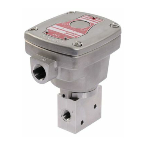
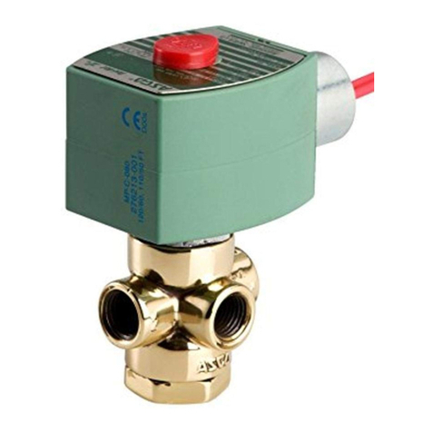
2 WAY DIRECT ACTING SOLENOID VALVES
3/8I, 1/2I, OR 3/4I NPT STEAM SERVICE
NORMALLY CLOSED OR NORMALLY OPEN OPERATION 8267
NOTICE: See separate solenoid installation and
maintenance instructions for information on: Wiring,
Solenoid Temperature, Causes of Improper Operation, Coil
or Solenoid Replacement.
DESCRIPTION
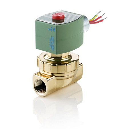
Series 8267 valves are 2-way normally closed or normally
open direct-acting solenoid valves. These valves are
designed for steam service. The guillotine- type disc
provides straight through flow, minimizing pressure drop
and tur ulence through the valve. Series 8267 valves may e
provided with a general purpose, raintight/explosionproof
or raintight/watertight/explosionproof solenoid enclosure.
OPER TION
Normally Closed: Valve is closed when solenoid is
De-energized; open when energized.
Normally Open: Valve is open when solenoid is
De-energized; closed when energized.
Note: No minimum operating pressure differential
required. See nameplate for maximum.
INST LL TION
Check nameplate for correct catalog num er,
pressure, voltage, frequency, and service. Never apply
incompati le fluids or exceed pressure rating of the valve.
Installation and valve maintenance to e performed y
qualified personnel.
Future Service Considerations
Provision should e made for performing seat leakage,
external leakage, and operational tests on the valve with a
nonhazardous, noncom usti le fluid after disassem ly and
reassem ly.
Temperature Limitations
For maximum valve am ient and fluid temperatures, refer
to chart a ove. Check catalog num er on nameplate to
determine maximum temperatures.
Catalog
Number
Coil
Insulation
Class
Maximum
Ambient
Temp.
Maximum
Fluid
Temp.
8267A1
8267A5
8267A9
8267A13
T8267B9
T8267B13
104_F
(40_C)
320_F
(160_C)
8267A3
8267A7
8267A11
8267A15
T8267B3
T8267B11
104_F
(40_C)
280_F
(138_C)
FT8267A11,
FT8267A1104974 F104_F
(40_C)
190_F
(88_C)
8267B7
8267B15 F86_F
(33_C)
250_F
(121_C)
8267B3
8267B11 F86_F
(33_C)
280_F
(138_C)
8267G1
8267G5
8267G9
8267G13
125_F
(51.7_C)
320_F
(160_C)
8267G3
8267G11 125_F
(51.7_C)
274_F
(134_C)
8267G7
8267G15 125_F
(51.7_C)
250_F
(121_C)
Positioning
Valve must e mounted with solenoid vertical and
upright.
Piping
Connect piping to valve according to markings on valve
ody. Apply pipe compound sparingly to male pipe threads
only. If applied to valve threads the compound may enter
the valve and cause operational difficulty. Avoid pipe strain
y properly supporting and aligning piping. When
tightening the pipe, do not use valve or solenoid as a lever.
Locate wrenches applied to valve ody or piping as close as
possi le to connection point.
CAUTION: To protect the solenoid valve, install a
strainer or filter, suitable for the service involved, in the
inlet side as close to the valve as possible. Clean
periodically depending on service conditions. See
ASCO Series 8600, 8601, and 8602 for strainers.
50-60 anover Road, Florham Park, New Jersey 07932 www.ascovalve.com ASCO Valves
Page 2 of 4 Form No.V5338R3
M INTEN NCE
WARNING: To prevent the possibility death,
serious injury or property damage, turn off
electrical power, depressurize valve, and vent
fluid to a safe area before servicing the valve.
NOTE: Piping must e removed from inlet side of valve
ody.
Cleaning
All solenoid valves should e cleaned periodically.
The time etween cleanings will vary depending on the
medium and service conditions. In general, if the
voltage to the coil is correct, sluggish valve operation,
excessive noise or leakage will indicate that cleaning is
required. In the extreme case, faulty valve operation
will occur and the valve may fail to open or close. Clean
valve strainer or filter when cleaning the valve.
Preventive Maintenance
1. Keep the medium flowing through the valve as free from
dirt and foreign material as possi le.
2. While in service, the valve should e operated at least
once a month to insure proper opening and closing.
3. Depending on the medium and service conditions,
periodic inspection of internal valve parts for damage or
excessive wear is recommended. Thoroughly clean all
parts. If parts are worn or damaged, install a complete
ASCO Re uild Kit.
Causes of Improper Operation
1. Incorrect Pressure: Check valve pressure. Pressure to
valve must e within range specified on nameplate.
2. Excessive Leakage: Disassem le valve and clean all
parts. If parts are worn or damaged, install a complete
ASCO Re uild Kit.
Valve Disassembly (Refer to Figure 1 &2)
1. Disassem le valve in an orderly fashion. Use exploded
views for identification and placement of parts.
2. Remove solenoid, see separate instructions.
3. Unscrew solenoid ase su -assem ly from valve ody.
4. Remove pipe adapter screws and lockwashers (2). Then
remove pipe adapter, adapter gasket, disc spring, and
disc guide from valve ody.
5. Slip core/disc su -assem ly with retainer guide
su -assem ly and core spring from valve ody
6. Remove solenoid ase gasket from valve ody.
7. Remove valve seat with seat gasket from valve ody.
CAUTION: During removal for cleaning, do not
damage seating surface of valve seat (see Figure
1&2).
NOTE: If seat removal is difficult, remove valve ody
from pipe line and dislodge seat through valve outlet. Use
a wooden dowel or similar tool.
8. All parts are now accessi le to clean or replace. If parts
are worn or damaged, install a complete ASCO Re uild
Kit.
Valve Reassembly
1. Lu ricate seat gasket with DOW CORNINGR 111
compound lu ricant or with an equivalent high-grade
silicone grease. Then install seat gasket in groove of valve
seat.
2. Insert valve seat gasket end first into valve ody. Use a
ru er tool to prevent damage to the seating surface of the
valve seat. Apply pressure until valve seat ottoms in valve
ody.
NOTE: When installing a vale seat in a 3/4I NPT valve
(see Figure 2) the elongated hole in the seat must e
aligned horizontal to mate with the hole in the core/disc
su -assem ly.
3. Install core/disc su -assem ly with sharp edge of hole in
core/disc su -assem ly toward valve seat.
4. Install disc guide large diameter end first into valve ody.
Then position disc spring on disc guide.
5. Lu ricate solenoid ase gasket and adapter gasket with
DOW CORNINGR 200 Fluid lu ricant or with an
equivalent high-grade silicone fluid.
6. Position adapter gasket on pipe adapter.
7. Install pipe adapter with gasket on valve ody.
CAUTION: Align pipe adapter evenly with
valve body to avoid damage to adapter gasket
8. Holding the pipe adapter in alignment, replace screws
with lockwashers (lockwashers use on 3/4I NPT valves
only). Torque screws evenly to 95± 10 in-l s
[10,5±1,1Nm].
9. Position solenoid ase gasket in valve ody.
10. Install core spring small end first into the top of the
core/disc su -assem ly. Then install retainer/guide
su -assem ly.
11. For 3/4INPT Valves with a raintight /explosionproof or
raintight/watertight/explosionproof solenoid enclosure,
torque onnet adapter to 175±25 in-l s [ 19,8±2,8 Nm].
12. Install solenoid ase su -assem ly into valve ody.
Torque solenoid ase su -assem ly to 300±30 in-l s
[33,9±3,4 Nm].
13. Replace solenoid (see separate instructions) and make
electrical hookup.
14. Makeup piping to inlet side of valve ody.
WARNING: To prevent the possibility of
death, serious injury or property damage,
check valve for proper operation before
returning to service. Also perform internal
seat and external leakage tests with a
nonhazardous, noncombustible fluid.
15. Restore line pressure and electrical power supply to
valve.
16. After maintenance is completed, operate the valve a few
times to e sure of proper operation. A metallic click"
signifies the solenoid is operating.
ASCO Valves
Page 3 of 4Form No.V5338R3
50-60 anover Road, Florham Park, New Jersey 07932 www.ascovalve.com
ORDERING INFORM TION FOR
SCO REBUILD KITS
Parts marked with an asterisk (*) in the exploded view are supplied
in Re uild Kits.
SWhen Ordering Re uild Kits for ASCO valves, order the Re uild
Kit num er stamped on the valve nameplate.+
+If the num er of the kit is not visi le, order y
indicating the num er of kits required, and the Catalog
Num er and Serial Num er of the valve(s)
for which they are intended.
retainer/guide
core spring
(small end in core first)
core/disc
seat gasket
valve seat
disc guide
disc spring
adapter gasket
pipe adapter
pipe adapter
valve body
solenoid base gasket
solenoid base
sub-assembly
solenoid base
sub-assembly
housing
solenoid bonnet
Torque solenoid base
sub-assembly to
300 30 in-lbs.
[33,9 3,4 Nm]
Indicates Parts Supplied
In ASCO Rebuild Kits
sub-assembly
sub-assembly
Torque pipe adapter
95 10 in-lbs.
[10,5 1,1 Nm]
+
_
+
_
+
_
+
_
Sharp edge of hole in
core/disc sub-assembly
must face valve seat
screw (2)
screws evenly to
gasket (not present
on all constructions)
Figure 1. Series 8267 valve without solenoid - 3/8I & 1/2I NPT shown.
CAUTION
Seating surface this end
Do Not Damage
50-60 anover Road, Florham Park, New Jersey 07932 www.ascovalve.com ASCO Valves
Page 4 of 4 Form No.V5338R3
core spring
(small end in core first)
valve body
solenoid base gasket
solenoid base
sub-assembly
retainer/guide
core/disc
sub-assembly
sub-assembly
seat gasket
valve seat
disc guide
disc spring
adapter gasket
pipe adapter
lockwasher (2)
CAUTION
Seating surface this end
Do Not Damage
Indicates Parts Supplied
In ASCO Rebuild Kits
solenoid base
sub-assembly
housing
pipe adapter
screw (2)
Torque pipe adapter
95 10 in-lbs.
[10,5 1,1 Nm]
+
_
+
_
screws evenly to
solenoid bonnet
gasket (not present
on all constructions)
core/disc
sub-assembly
valve seat
bonnet adapter
Torque solenoid base
sub-assembly to
300 30 inch pounds
[33,9 3,4 newton-meters
+
_
+
_
Torque bonnet adapter to
175 25 inch-pounds
[19,8 2,8 newton-meters]
+
_
+
_
Figure 2. Series 8267 valve without solenoid - 3/4I NPT shown.
Sharp edge of hole in
core/disc sub-assenbly
must face valve seat
solenoid base
gasket
align elongated hole in
valve seat with hole in
core/disc sub-assembly
When installing valve seat,
PARTIAL VIEW

This manual suits for next models

26

Other Asco Control Unit manuals

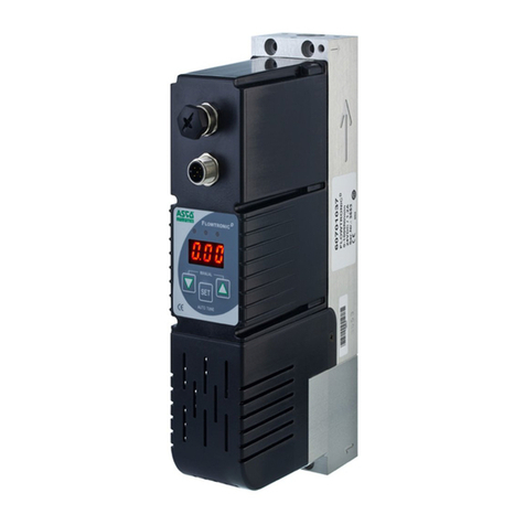
Asco JOUCOMATIC SENTRONIC 601 Series User manual

Asco

Asco JOUCOMATIC SENTRONIC 601 Series User manual

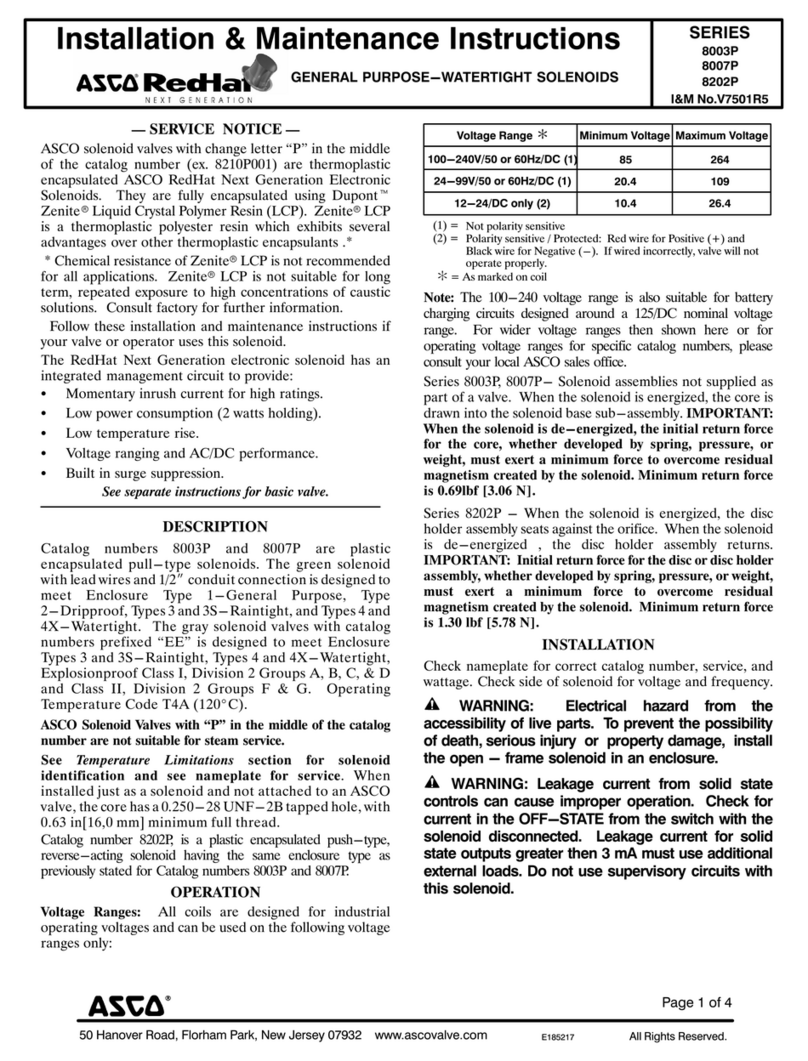
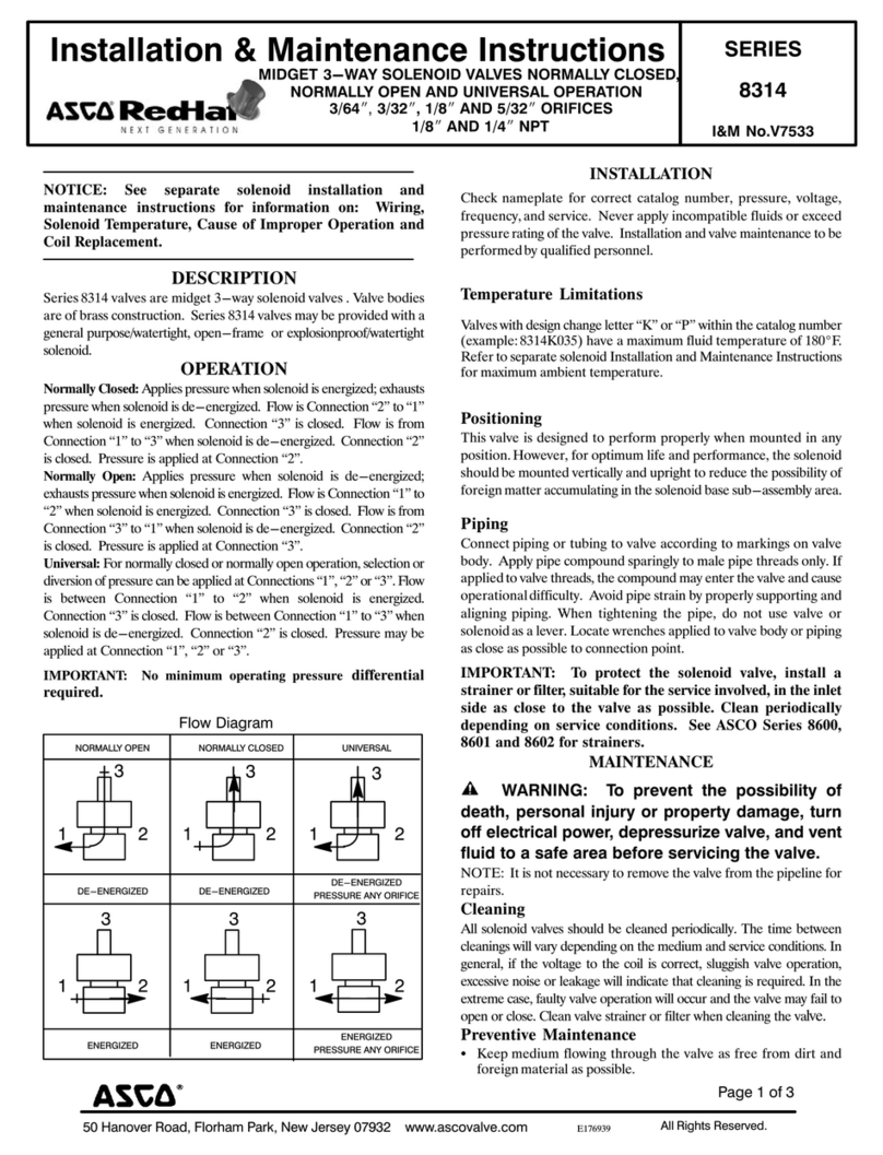
Asco RedHat 8314 Series Installation and operating instructions

Asco

Asco RedHat 8314 Series Installation and operating instructions

Asco 8215 Series Installation and operating instructions

Asco

Asco 8215 Series Installation and operating instructions

Asco 290 Series User manual

Asco

Asco 290 Series User manual

Asco 551 Series User manual

Asco

Asco 551 Series User manual

Asco 8551 Series Installation and operating instructions

Asco

Asco 8551 Series Installation and operating instructions

Asco 8030 Series Installation and operating instructions

Asco

Asco 8030 Series Installation and operating instructions

Asco 8030 Series Installation and operating instructions

Asco

Asco 8030 Series Installation and operating instructions

Asco 8042 Series Installation and operating instructions

Asco

Asco 8042 Series Installation and operating instructions

Asco JOUCOMATIC FLOWTRONICD 607 User manual

Asco

Asco JOUCOMATIC FLOWTRONICD 607 User manual

Asco 290 Series Instruction Manual

Asco

Asco 290 Series Instruction Manual

Asco 8214G54 Installation and operating instructions

Asco

Asco 8214G54 Installation and operating instructions

Asco 8210 series Installation and operating instructions

Asco

Asco 8210 series Installation and operating instructions

Asco RedHat 8321 Series Installation and operating instructions

Asco

Asco RedHat 8321 Series Installation and operating instructions

Asco 8316 Series User manual

Asco

Asco 8316 Series User manual

Asco 8344 Series User manual

Asco

Asco 8344 Series User manual

Asco 290 Series User manual

Asco

Asco 290 Series User manual

Asco ARCS 141 Series User guide

Asco

Asco ARCS 141 Series User guide

Asco 8316 Series Installation and operating instructions

Asco

Asco 8316 Series Installation and operating instructions

Asco 290 Series User manual

Asco

Asco 290 Series User manual

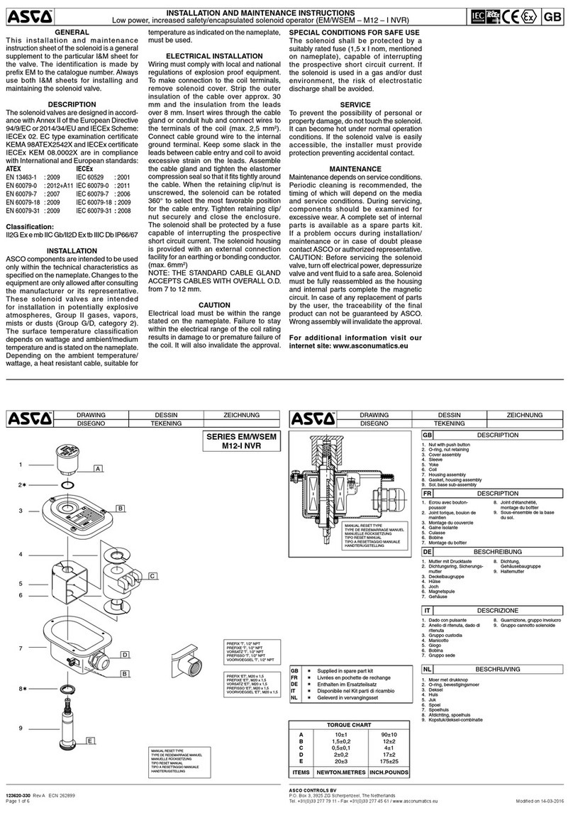
Asco 8320 Series Installation and operating instructions

Asco

Asco 8320 Series Installation and operating instructions

Asco 290 Series User manual

Asco

Asco 290 Series User manual

Asco 8220 Series Installation and operating instructions

Asco

Asco 8220 Series Installation and operating instructions

Asco 8210 Series Installation and operating instructions

Asco

Asco 8210 Series Installation and operating instructions

Popular Control Unit manuals by other brands

Niko 340-00111 manual

Niko

Niko 340-00111 manual

Flomatic Comboair installation instructions

Flomatic

Flomatic Comboair installation instructions

Nordson EFD 736HPA Maintenance & Parts Guide

Nordson EFD

Nordson EFD 736HPA Maintenance & Parts Guide

elsner elektronik IMSG 230 compact Technical specifications and installation instructions

elsner elektronik

elsner elektronik IMSG 230 compact Technical specifications and installation instructions

CALEFFI 510 Series quick start guide

CALEFFI

CALEFFI 510 Series quick start guide

Chroma Uploader II quick start guide

Chroma

Chroma Uploader II quick start guide

HKS Super SQV IV 71008-AK001 manual

HKS

HKS Super SQV IV 71008-AK001 manual

Niobrara QUCM 3964 Installation and programming manual

Niobrara

Niobrara QUCM 3964 Installation and programming manual

WEG DBW03 Series user manual

WEG

WEG DBW03 Series user manual

EOS ECON A2 Installation and user manual

EOS

EOS ECON A2 Installation and user manual

ExTox ET-1D Series instruction manual

ExTox

ExTox ET-1D Series instruction manual

Huawei MU509-b Application guide

Huawei

Huawei MU509-b Application guide

Spirax Sarco 5953 Series Installation and maintenance instructions

Spirax Sarco

Spirax Sarco 5953 Series Installation and maintenance instructions

H3C PSR450-12A user manual

H3C

H3C PSR450-12A user manual

Seraphim SRP-XXX-6PA-BB installation guide

Seraphim

Seraphim SRP-XXX-6PA-BB installation guide

Parker Racor RK19506 instructions

Parker

Parker Racor RK19506 instructions

Festo CDVI5.0 Assembly instructions

Festo

Festo CDVI5.0 Assembly instructions

Bartec APEX px operating instructions

Bartec

Bartec APEX px operating instructions

manuals.online logo
manuals.online logoBrands
  • About & Mission
  • Contact us
  • Privacy Policy
  • Terms and Conditions

Copyright 2025 Manuals.Online. All Rights Reserved.