Asoni CAM414 User manual

Network Vandal Dome
CAM414 / CAM415
User’s Manual
Version: 3.1
Date: 5/22/2008

1
Content
1. Preface .................................................................................................................................2
2. Product Specifications...........................................................................................................2
3. Product Installation ...............................................................................................................4
A. Hardware Installation.........................................................................................................4
B. Monitor Setting..................................................................................................................6
C. IPAssignment ...................................................................................................................7
D. Install ActiveX Control .......................................................................................................9
4. Live Video...........................................................................................................................11
5. Configuration ......................................................................................................................14
A. System............................................................................................................................14
B. A/V Setting......................................................................................................................20
C. Network...........................................................................................................................25
D. Event Handling................................................................................................................29
6. Network Configuration ........................................................................................................37
Appendix....................................................................................................................................39

2
1. Preface
CAM414/415 Network Vandal Dome is a professional CCD Network Vandal Dome. It
builds in web server. User views real-time video via IE browser.
Network Vandal Dome supports MPEG-4 & M-JPEG video compression which provides
smooth and high quality video. The video can be stored in the SD card, and can be
playback remotely.
The PoE model built-in support for Power over Ethernet allows the camera to receive both
data and power over a single Ethernet cable.
2. Product Specifications
zMPEG-4 / MJPEG compression formats. Supports resolution up to 30/25 fps @ Full
D1 (720x480 / 720x576)
zMPEG-4 / MJPEG dual streaming.
zSelf-Contained HTTP Web Server providing Internet capability for remote access
zBuilt-in IR LED for day/night usage (CAM415)
zSupports SD card for local recording
z2-way audio
zUnbreakable housing
zSupport IP66 water proof standard
zBuilt-in support for Power over Ethernet (available for PoE models)
zReal-time video recording
zRecorded files compatible with Microsoft Windows Media Player
Hardware
Model CAM414 CAM415
Picture Elements H×V NTSC:510×492, PAL: 500×582 NTSC:768×494, PAL: 752×582
Horizontal Resolution More than 420 TV Lines More than 540 TV Lines
Image Sensor 1/3” CCD
Lens CAM414/415: 3.7~12mm vari-focal auto iris, F1.6, 3.6mm
CAM414F/415F: Fixed lens 3.6mm
IR LED - IR LED Built-in

3
IR Cut Filter - Removable IR Cut Filter (optional)
Sensitivity 0.05 lux 0.1 lux, 0 lux (IR On)
CPU ARM 9 ,32 bit RISC
RAM 64MB
ROM 8MB
Video Out 1 Vp-p, 75 Ohms
Digital I/O 1 In/ 1 Relay out (COM. & N.O.)
Audio In / Out 1 In / 1 Out
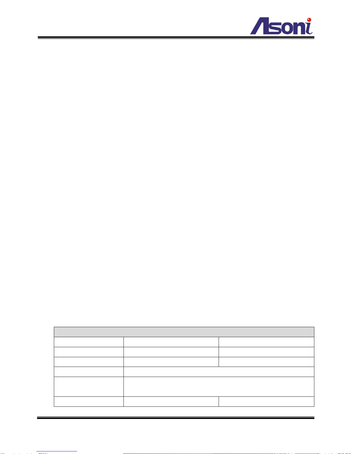
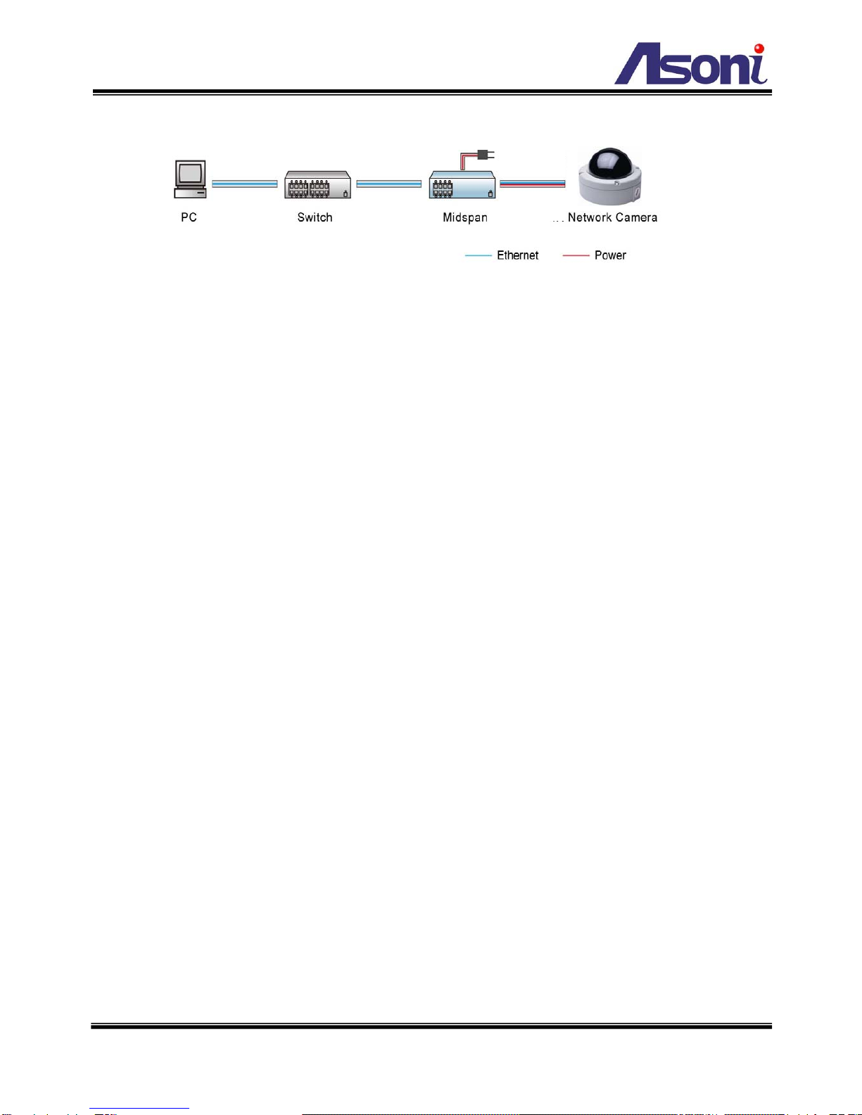
Power Consumption DC12V, 490mA PoE model: Built-In PoE (IEEE 802.3af)
Network
Ethernet 10/ 100 Base-T
Network Protocol HTTP, TCP/IP, RTP/RTSP, 3GPP, SMTP, FTP, PPPoE, DHCP, DDNS, NTP
System
Video Resolution NTSC: 720x480, 704x480, 352x240, 176x120
PAL: 720x576, 704x576, 352x288, 176x144
VideoAdjustment Brightness, Contrast, Saturation, Hue
Image Snapshot Yes
Full Screen Monitoring Yes
Compression Format MPEG-4, MJPEG
Dual Streaming Yes, MPEG-4 / MJPEG
Video BitrateAdjustment CBR, VBR
Motion Detection Yes, 3 different areas
Triggered Action Mail, FTP, Digital out, Save to SD card
Pre/ Post Alarm Yes, configurable
Security Password protection
Firmware Upgrade HTTP mode, can be upgraded remotely
Simultaneous Connection Up to 10
Audio Yes, 2-way
SD card management
Recording Trigger Motion detection, Digital input, IP check, Network break down
Video Format AVI, JPEG
Video Playback Yes
File Management Yes, can be deleted or overwrite
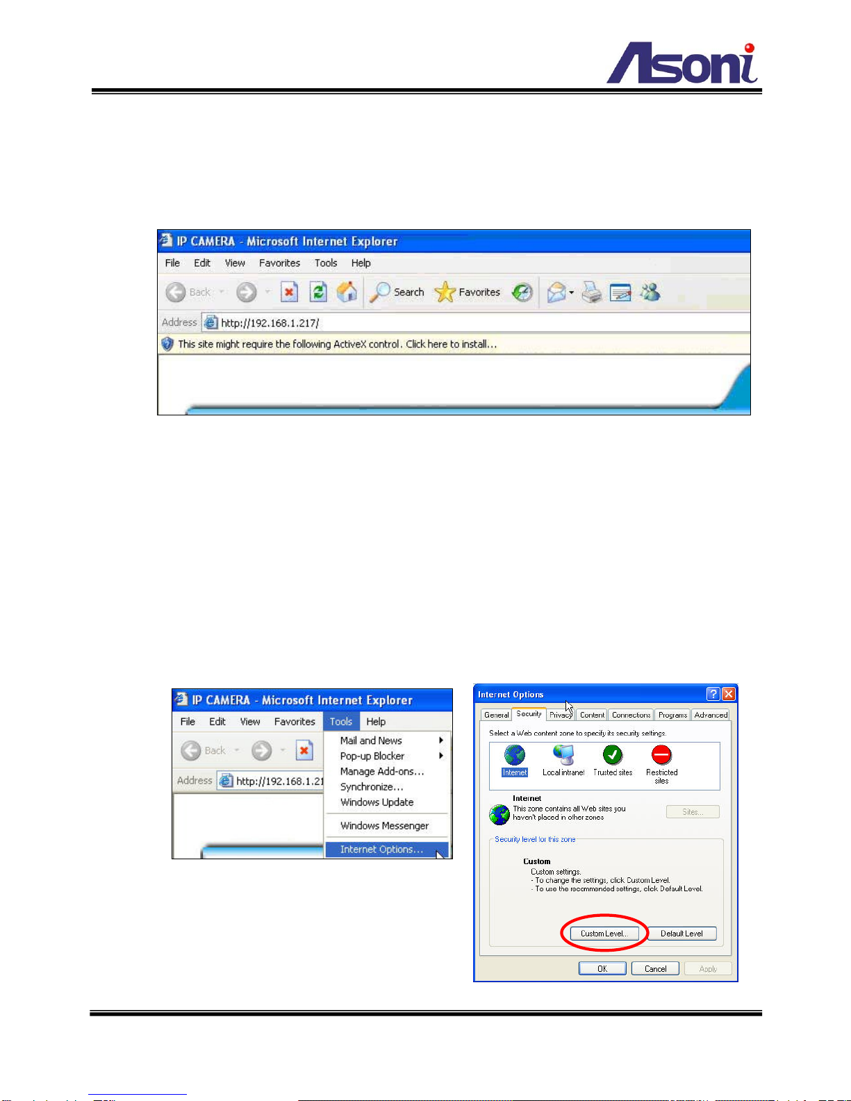
Web browsing requirement
OS Windows 2000, XP, 2003, Microsoft IE 6.0 or above
Hardware Suggested Intel-C 2.0G, RAM: 512MB, Graphic card: 64MB
Minimum Intel-C 1.6G, RAM: 256MB, Graphic card: 32MB

4
3. Product Installation
A. Hardware Installation
nPower Jack: To connect the included power adapter.
oDigital I/O: Digital In and Digital Out.
pVideo Output: The BNC connector allows connect to the analog display to
output analog video for locally monitoring.
qAudio Input (Pink): The RCA connector allows connect to a microphone or audio
source, the connected audio will be heard at the remote site.
rAudio Output (Green): The RCA connector allows connect to an amplified speaker,
you can hear the voice of the remote site from the speaker.
sNetwork Connector: The RJ-45 connector allows connect the Ethernet cable.
1. Connect the cable of Digital I/O, Video output, Audio output and Audio input if you want
to use these functionalities.
2. Connect Ethernet cable for network connection.
3. Connect power adapter to turn on the camera.
4. If the camera is PoE model, the power adapter is not necessary. The camera will get
the power from the Ethernet cable. Please follow the below figure for the connection.
n
o
p
q
r
s
Power Jack (DC 12V)
Digital I/O
Analog Video Output
(Pink) Audio Input
(Green) Audio Output
Network Connector

5
5. Set up the network configurations according to the network environment. For further
explanation, please refer to chapter 6.

6
B. Monitor Setting
1. Right-Click on the desktop. Select [Properties]
2. Change color quality to “Highest (32bit)”.

7
C. IP Assignment
¾Always consult your network administrator before assigning an IP address to your
camera in order to avoid using a previously assigned IP address.
¾MAC Address: Each network camera has a unique Ethernet address (MAC address)
shown on the sticker of the camera.
¾One final note, although the IP Search is able to find and configure any network
camera on the LAN except those that are behind a router, it is a good idea to set the
host PC to the same subnet. In order to connect to the Web-based user interface of
the network camera, the host PC must be in the same subnet. For more information
about subnets, please consult your network administrator.
There are 3 kinds of IP configuration:
zFixed IP (Public IP or Virtual IP)
zDHCP (Dynamic IP)
zDial-up (PPPoE)
IP Search is a utility that provides an easier, more efficient way to configure the IP
address and network settings of the network camera. It even provides a convenient way
to set the network settings for multiple devices simultaneously. Moreover, IP Search can
save the network settings for all devices as a backup and restore them when necessary.
The software can be installed from the attached software CD.
1. Once IP Search has been successfully installed on the computer, double click the
IP Search icon on the desktop.

8
2. IP Search searches all the network devices which connect to the intranet and lists
on the window. Click [Search] button to search again.
3. From the list, select the device with the MAC Address that corresponds to the
device that is to be configured.
4. Click one of the network devices, the network configuration of this device will show
on the bottom.
5. After filling in the IPAddress, Subnet Mask, Gateway and the others, click [Set]
button to complete the configuration settings and save into the remote device.
6. You can assign a name to identify the camera. Type the name in “Device Name”
field, click [Save] and then click [Search] button, the name will be displayed in the
list.
7. Wait for 1 minute to let camera update the settings, and then click [Search] button
again to re-search the network devices. Click the network device listed on the
window and click [Open Web] button. It will open an IE browser and connect to this
device directly.

9
D. Install ActiveX Control
For the first time to view the camera video via IE, it will ask you to install the ActiveX
component.
If the installation failed, please check the security setting for the IE browser.
1. In IE, click on [Tools] Æ[Internet Options…]
2. Click on [Security] Tab Æ[Custom Level…]
3. In Security Settings, under [Download unsigned ActiveX controls], select “Enable”
or “Prompt”.
4. In Security Settings, under [Initialize and script ActiveX controls not marked as safe],
select “Enable” or “Prompt”.
5. When pop-up window with warning message, click [Yes] to save the settings.
1 2

10
3 4
5
When popup the following dialogue box, click [Yes].

11
4. Live Video
Start the IE browser, type the IP address of the
network camera in the address field. It will
show a dialogue box. Key-in the user name
and password.
The default user name and password are
“admin” and “admin”.
When connect to the CAM414/415, the following GUI shows.
⑤
④
③
②
①

12
nStreaming : If the streaming 2 is enabled, select the streaming from the pull-down list
to display.
oConfiguration : Go into the configuration page to set the parameters if necessary.
pShows system date/time, video resolution and video refresh rate (FPS).
qOnline Visitor : Shows how many users connect to this network camera.
rFunction Buttons : Click these buttons will perform the following functions.
Fit to Window : Resize the video to fit the window for view. Click this button
again to back to the original size.
Full Screen : Click this button or double-click the video, the video will change
to full screen mode.
Press [Esc] key or double-click the video again, it will change back to normal
mode.
Snapshot : Click this button to take snapshot of the video. The image will be
displayed in a pop-up window, click to save as a jpg picture.
Record : Click this button to record the video into the local PC. It will ask you
where to save the video. To stop recording, click this button again.
The saved video format is AVI. The recorded file can be played by Microsoft
Media Player. Note, MPEG4 decoder must be installed to play the recorded
file. You can install “FFdshow” from the included CD for the decoder.
Chatting : The camera supports 2-way audio. Click this button, then you can
use microphone which connected to the PC to talk to the camera side.
Voice : Click this button to turn on the audio from camera. Click again to turn
off it.
Zoom : Click this button, a
pop-up window appears. You
can enable / disable the digital
zoom, and adjust the ratio.

13
Relay Out (ON/OFF Switch) : Click the button to manually turn on / off the
Relay via the built-in Digital Out.
Relay Out (Time Switch) : Click the button to manually turn on the Relay via
the built-in Digital Out, after the interval time is passed, the Relay will be
turned off automatically. The interval time can be set up in “Configuration” ->
“Event Handling” -> “I/O”.

14
5. Configuration
Click [Configuration] button to get into the configuration page. Click [Live View]
button to back to the live video page.
A. System
System Information
Set up the camera name, select language, and set up the camera time.
Server Name
This is the Camera name.
Information

15
Language
Select the language for the user interface.
OSD Setting
Enable this option will display the date and time on the video. The display position can
be selected.
Time Setting
Date Format: Select the format to display the date.
Time Zone: Select the GMT to match your time zone.
Synchronize with NTP Server: Select this option will synchronize the camera time
with the NTP server via network.
Synchronize with PC’s time: Select this option will synchronize the camera time with
the PC’s time.
Input Date & Time: Manually input the date and time.
The date and time remain the same: Keep the current date and time without change.
After set up, click [Apply] to save the settings.

16
User Management
You can add, remove and manage the users in this page.
Add User
To add a new user, type the user name and password, then click [Add/Set] to save the
user.
User List
Edit: To change the username and
password, click [Edit] and modify the user
in the pop-up window.
Remove: To remove the user, click
[Remove].
User

17
System Update
This page allows user to upgrade firmware, restart camera and manage the settings.
Firmware Upgrade
The firmware can be upgraded online. Note, after upgrade firmware, all settings
including Network, A/V and Event settings will be restored to the factory defaults. We
strongly recommend you save the current settings before upgrade the firmware, and
then reload the settings after upgrade.
To update the firmware, click [Browse…] to select the new firmware file, and then click
[Upgrade] to the procedure.
Reboot System
To restart the camera, click [Start] and then click [Yes] on the prompted window.
Factory Default
To load the factory defaults, click [Start] and then click [Yes] on the prompted window.
Note, all settings including Network, A/V and Event settings will be restored to the
factory defaults.
Setting Management
Save As a File: To backup the current settings to PC, right-click [Setting Download]
and click [Save AS…] in the context window, select a location to save the file. The
filename of this file is “Settings.CFG”.
System
Update

18
New Setting File: To load the backup settings into the camera, click [Browse…] to
select the file (filename is “Settings.CFG”), and then click [Upgrade].

19
Log List
System Logs
Click the [Logs] button on the right side to list the logs of system status.
Motion Detection Logs
Click the [Logs] button on the right side to list the logs of motion detection.
I/O Logs
Click the [Logs] button on the right side to list the logs of digital input and output.
All Logs
Click the [Logs] button on the right side to list all logs.
Log List
This manual suits for next models
1
Table of contents
Other Asoni Security Camera manuals

Asoni
Asoni CAM746F User manual

Asoni
Asoni CAM624M User manual

Asoni
Asoni CAM6833EV User manual

Asoni
Asoni CAM713M User manual

Asoni
Asoni CAM640 User manual

Asoni
Asoni CAM410 User manual

Asoni
Asoni CAM413 User manual

Asoni
Asoni CAM678H User manual

Asoni
Asoni CAM737MIR User manual

Asoni
Asoni CAM641 User manual