Asus P750 Assembly instructions

GTC ■Service Manual
ASUS P750 Repair Guide
(Level 3 4) Ver 1.0b
ASUS Proprietary1

GTC ■Service Manual
ASUS Proprietary2
華
華碩
碩電
電腦
腦
CONTENT
1.
PRODUCT GENERAL SPECIFICATION.............................................4
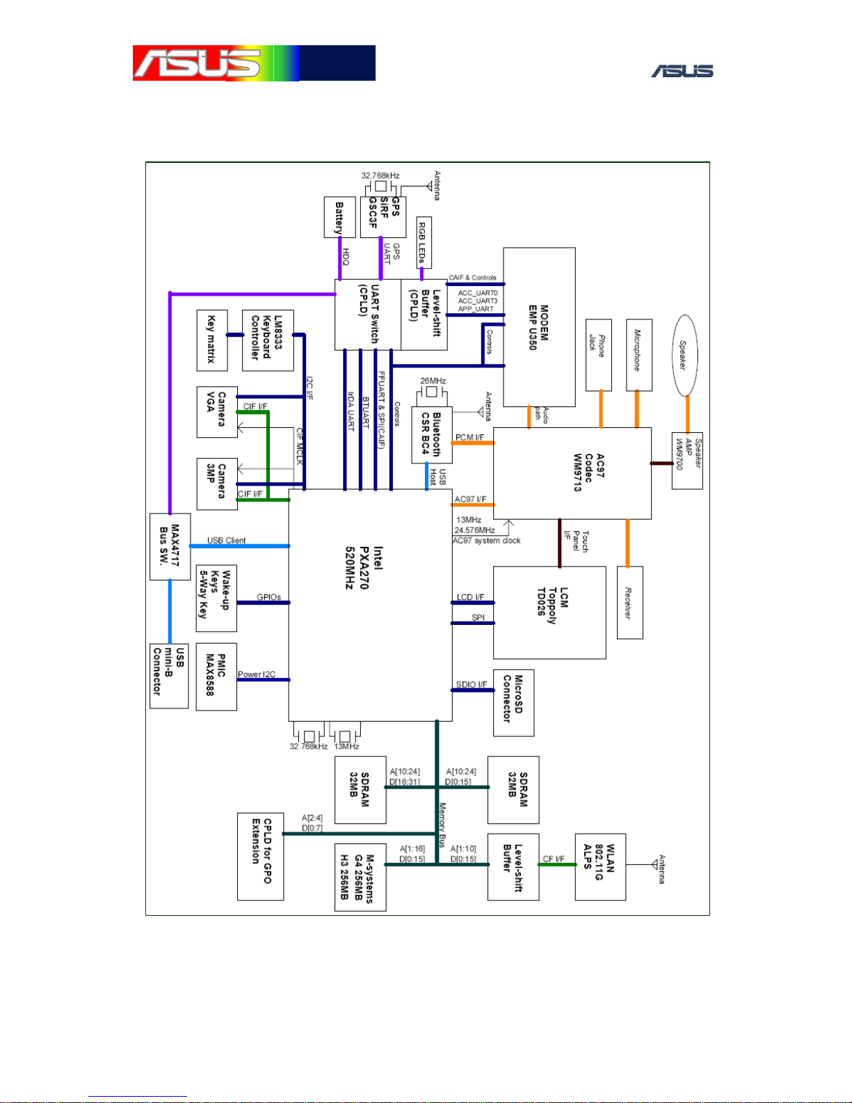
2.
BLOCK DIAGRAM...................................................................................6
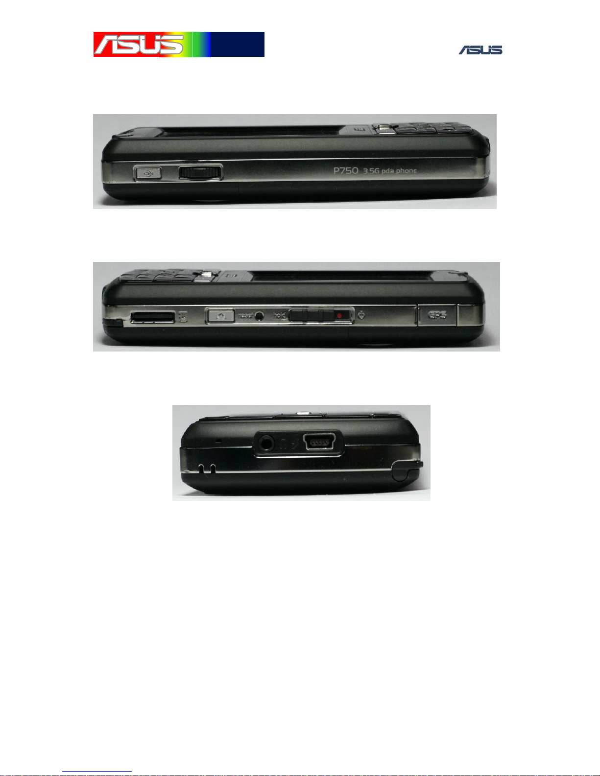
3.
APPEARANCE...........................................................................................7
3.1 FRONT VIEW................................................................................................7
3.2 SIDE VIEW ...................................................................................................8
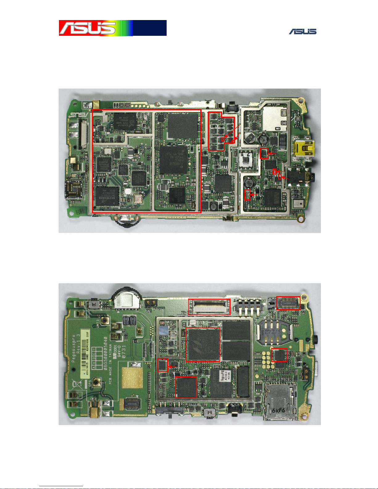
4.
PCB PLACEMENT....................................................................................9
4.1 MAIN BOARD TOP VIEW..............................................................................9
4.2 MAIN BOARD BOTTOM VIEW ......................................................................9
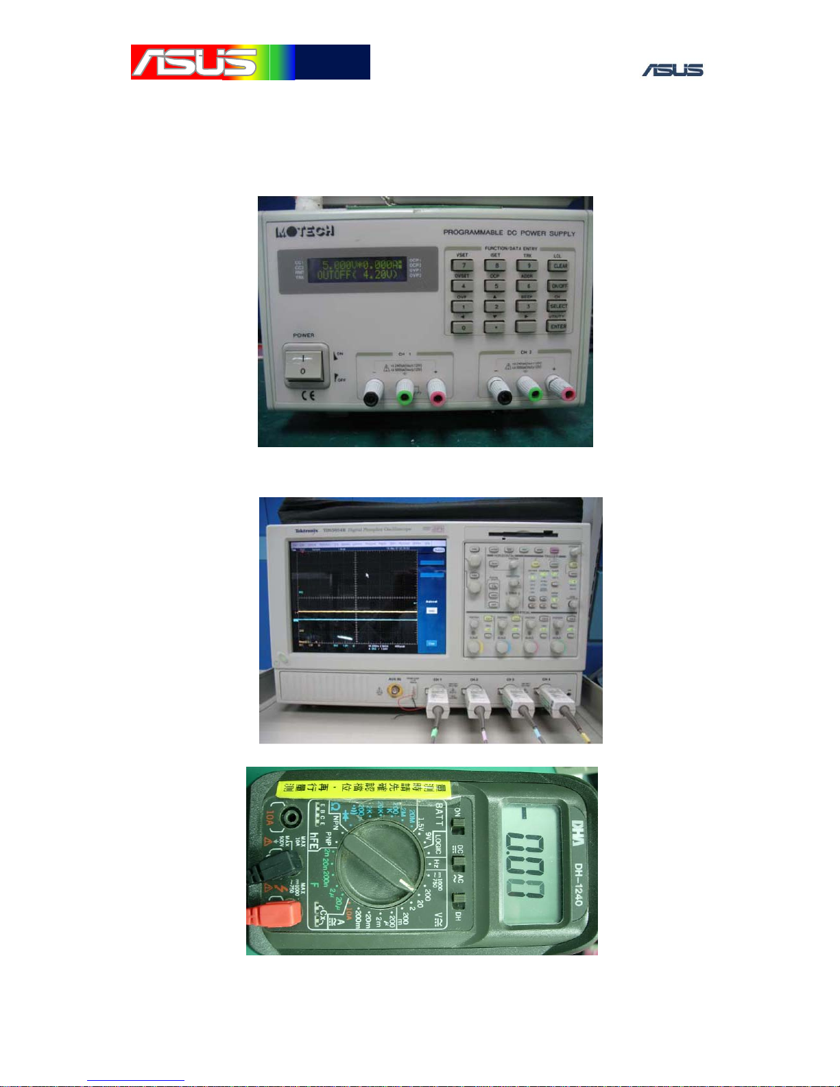
5.
EQUIPMENT LIST .................................................................................10
5.1
HARDWARE ..........................................................................................10
6.
TROUBLE SHOOTING CASE..............................................................12
6.1 SYSTEM CAN’T BOOT!................................................................................12
6.1.1 Power on sequence............................................................................12
6.1.2 CPU BGA ..........................................................................................13
6.1.3 NAND Flash ......................................................................................13
6.2 MMI TEST ITEM ........................................................................................14
6.2.1 Display Test.......................................................................................14
6.2.2 Vibrator Test......................................................................................15
6.2.3
RTC Test.............................................................................................15
6.2.4
Storage Test .......................................................................................15
6.2.5
Micro SD Test....................................................................................16
6.2.6
LED Test ............................................................................................16
6.2.7 Camera Test & VGA Camera............................................................18
6.2.8 Check SIM .........................................................................................20
6.2.9 Battery Test........................................................................................21
6.2.10 SDRAM Test ....................................................................................22
6.2.12 Turn On/Off Radio...........................................................................25
6.2.13 Version Check..................................................................................27
6.2.14 Keypad Test..................................................................................... 27
6.2.15 WiFi Board-Level Test ....................................................................29

GTC ■Service Manual
ASUS Proprietary3
華
華碩
碩電
電腦
腦
6.2.16 GPS Firmware Update....................................................................29
6.2.17 PS Board-Level Test........................................................................29
6.2.18 TMC Test .........................................................................................30
6.2.19 BT Board-Level Test........................................................................ 30
7.
POWER CONSUMPTION .....................................................................31
7.1 POWER OVER STANDARD............................................................................31
7.2 CPU CONSUMPTION TOO HIGH ..................................................................31
7.3 CAMERA SHORT .........................................................................................32
7.4 Others
................................................................................................32
8.
RF LAYOUT PLACEMENT..................................................................33
9.
RF BLOCK DIAGRAM ..........................................................................34
9.1 TRANSMIT MODE .......................................................................................36
10.
WCDMA................................................................................................40
10.1 PLACEMENT -WCDMA ..........................................................................40
10.2 WCDMA TX PATH.................................................................................42
10.3 TX MEASUREMENT..................................................................................43
10.4 TEST PROCEDURE:....................................................................................45
10.5 WCDMA RX ..........................................................................................51
10.6 WCDMA RX PATH MEASUREMENT .......................................................53
10.7 RX TEST PROCEDURE ..............................................................................54
10.8 WCDMA PA POWER CONTROL ..............................................................60

GTC ■Service Manual
ASUS Proprietary4
華
華碩
碩電
電腦
腦
1. Product General Specification
Networking system HSDPA 3.6Mbps, UMTS 2100,
EDGE/GSM 900/1800/1900; GPRS Class B
Operating System Microsoft Windows Mobile 6 Professional
CPU Marvell PXA270M 520MHz
Dimensions 113 x 58 x 17.4 mm, 130g
Battery 1300 mAh Lithium-Ion
Talk time 300 mins for 3G, 360 mins for 2G
Standby time 240 hours for 3G, 220 hours for 2G
Form Factor Bar type with numeric keypad
Color Black
Display 2.6“ Touch Screen / 65K TFT LCD / 240 x 320
Connectivity WLAN 802.11 b+g / Bluetooth 2.0+EDR /
USB v1.1
Browsing HTML 4.01, WAP 2.0 (IE)
Messaging SMS/MMS/Email/MSN/Push E-mail
Memory 256 MB Flash + 64 MB SDRAM
Expansion Slot Micro-SD (SDHC supports)
GPS GPS (SiRF III with internal antenna), AGPS
(need to co-work with local operators) , TMC
(optional cable)
JAVA J2ME (CLDC 1.1 + MIDP2.0)
Camera 3 Mega-Pixel (Auto focus)
Audio MP3, WMA, AAC, AAC+, 3GP

GTC ■Service Manual
ASUS Proprietary5
華
華碩
碩電
電腦
腦
Video MPEG4 / H.263 Playback and Recording
Ringtone 128-ch Polyphonic ringer & MP3
PIM/Utilities Notes, Calendar, Alarm, and Windows Live
Messenger, Word (editor), Excel (editor), and
Power Point (viewer)
Advanced Ur Time,
Backup,
ASUS Launcher,
Voice Commander,
Bluetooth Remote Presenter,
Travelog,
Location courier,
Business Card Recognition,
Newstation,
Meeting planner,
Auto cleaner,
GPS catcher,
OMA DRM V2.0

華
華碩
碩電
電腦
腦GTC ■Service Manual
ASUS Proprietary6
2. Block Diagram

華
華碩
碩電
電腦
腦GTC ■Service Manual
ASUS Proprietary7
3. Appearance
3.1 Front View

華
華碩
碩電
電腦
腦GTC ■Service Manual
ASUS Proprietary8
3.2 Side View

GTC ■Service Manual
ASUS Proprietary9
華
華碩
碩電
電腦
腦
4. PCB Placement
4.1 Main Board Top View
4.2 Main Board Bottom View
Logic
Block PWR_EN
BAT_FAULT#
V_BKBT
U44
WIFI
VBAT
SYS_EN
MODE
M
U42
U1
U600
con1 con3
U90

華
華碩
碩電
電腦
腦GTC ■Service Manual
ASUS Proprietary10
5. Equipment List
5.1 Ha
er supply (Monitor current)
igital Phosphor Oscillo
igital Meter
rdware
Power source: pow
D scope
D

華
華碩
碩電
電腦
腦GTC ■Service Manual
ASUS Proprietary11
Mechanical Auxiliary Tool & tooling
‧Screwdriver ( T5 * Cross + )
‧Tweezers
‧Plastic Wrench
Micro SD

GTC ■Service Manual
ASUS Proprietary12
華
華碩
碩電
電腦
腦
6. Trouble shooting Case
6.1 System can't Boot!
The main of the reason is related for component short and incorrect in
“Power-On Sequence” issues. First, we can check the Current of the device
during the OS booting process then try to measure the “Power ON
Sequence”. In P750 design concept; The System will auto Power On in two
conditions One is first connect to device, another the voltage drop below
2.8V m than 2.8V, the system should
nhe reset button
until the power supply working when we want to make sure the OS booting
pro
6
P
.3V
Must inspect the soldering status to eliminate
iode reverse issue ) .
booting abnormal.
C. VCC_3.0V, VCC_1.8V, VCC_CORE > 1.3V, VCC_PLL = 1.3V,
ect of the voltage then we can try to check the
D.
E.
The Item C is noraml but the SYS_EN / PWR_EN< 2.9V.It always the solder
issue fo
fro backup battery. If the voltage more
ot booting automatically. It is recommendation for hold on t
cess is activated.
.1.1 Power on sequence
lease check “Power on Sequence“ for each Voltage:
A. V_BAT = power supply voltage
The proposal of V_BAT is for System power.
The check point is C228.1
B. V_BKBT = 3
If V_BKBT < 3.3V,
the component U44 defective ( floating and d
It will cause the charged failure for the backup battery and OS
VCC_SRAM = 1.1V
If found the incorr
soldering floating or mistake component (U41, L8, L9, L10).
SYS_EN = 2.9V
PWR_EN = 2.9V
r CPU( U1). Try to rework the U1 and replace it.

華
華碩
碩電
電腦
腦GTC ■Service Manual
ary
ASUS Propriet13
F.
Please check U33,
U50) .
6.1.2 CP
If the answer is well it
maybe the CPU BGA issue or Chip defective. We can change the CPU to
im ng the manufacture experience for the CPU
NAND Flash
ata can’t response from TP28 ( SD15 ), in my opinion is
Figure 1. PMU
BAT_FAULT# = 3.3V
the floating and diode reverse issue on the component (C337,
U BGA
If the device still didn’t work after item 1 trace, we can measure the signal
T12 ( NAND_CS# ) should be get the high-low transition by oscillate
scope. Check the data response from TP28 (SD15).
prove the situation. Accordi
which replace in time will be failure for the work.
6.1.3
In Item 2, if the d
try to re-flash the data to NAND flash via JTAG.

華
華碩
碩電
電腦
腦GTC ■Service Manual
ASUS Proprietary14
Figure 2. Battery fault mechanism
6.2 MMI Test Item
6.2.1 Display Test
The item is focus verify the function ”LCM interface” and ”backlight”,
please check the below item if the result is “No Go”.
A. LCD_PWR_EN
B. LCD_3.0V 2.9V
.LCD_RESET# 2.9V
D. LCD_FCLK, LCD_LCLK, LCD_PCLK should exist the clock signal for
LCD panel. If we can not measure the signal should be check the soldering
resistor (R19, R20, R21).
E. LCD_DATA_EN 2.9V
bnormal mean CPLD NG. The
normal expose should be check the LCD0 ~
t 1. If we can’t get improve the signal status
e should measure
f
1.8V
C
/floating each side on
,
The white screen will happen from above items. If
“LCD_PWR_EN/LCD_RESET#” a
color deviation or ab
LCD15 with he CON
after change or re-work the CON1, the main of the reason should be
CPU NG.
F. V_LED 12V
If the backlight can not active on the LCD panel, w
the 12V on the “V_LED”. If not then check the relate components o
the U48.

華
華碩
碩電
電腦
腦GTC ■Service Manual
ASUS Proprietary15
6.2.2 V
It is less probity low for the item” board-level fail”. We can check the
U86 SMT or component defective issue.
U86
U86
It should be U6 (Flash m ponent
defective.
ibrator Test
below status for charge the
.4 2.9V
.1 3.3V
Figure 3. Vibrator mechanism
6.2.3 RTC Test
We can measure the 32.768 for X2 clock signal. We can try to replace
the CPU and X2 on this item failure.
6.2.4 Storage Test
emory) on soldering issue or com

華
華碩
碩電
電腦
腦GTC ■Service Manual
ASUS Proprietary16
6.2.5 Test
e can check the below signal list to verify the Micro SD function.
.MMC_PWR_EN 2.9V ->If not U600 NG.
.MMC_3.0V 2.9V->If not check U87 soldering issue.
circle ”Red->Green->B er the LED twinkled
at
A. RGB LED Abnormal
LED signal is controlled by CPLD. The behavior code is
n PCB.
00.
Micro SD
W
A
B
Figure 4. micro SD Power
Ps. The position of the Micro SD Socket had the mechanical position
declination. So the SD card still exist detect but it will cause lodged for
SD insert at assembly test.。
6.2.6 LED Test
The test item is for Red, blue, green Led die and key pad LED could
works. The scenario will step by step to follow the
lue” on indicated LED. Aft
1 Hz then keypad white LED also twinkle the key panel.
The RGB
no exist in CPLD which will cause the RGB LED always
illuminated red light. Please replace the CPLD o
If one of the colors can’t works on RGB LED, please check the
soldering issue on R621, R622, R623 or replace the LED6

華
華碩
碩電
電腦
腦GTC ■Service Manual
ASUS Proprietary17
Figure 5. Indication LED Circuit
B. Keypad LED failure
Please measure the U88.4 (KEY_LED_EN) ->2.9V,if the result is
true please check the U88.
Figure 6. Keypad LED power

華
華碩
碩電
電腦
腦GTC ■Service Manual
ASUS Proprietary18
6.2.7 Camera Test & VGA Camera
The main of the reason is for assembly issue and component defective.
The camera’s function can’t work on component defective issue. For
example: dirty lens, can’t auto focus.
Caution: The VGA socket didn’t support one direction assembly. If
VGA camera direction incorrect, it wi cause the booting failure.
If the above the item already finish, try to refer to below issue.
If the signal is abnormal please try to change U600 ( CPLD).
ll
CMOS_3.0V 2.8V
VAAM 2.8V (For Auto focus Motor power Source)
Figure 7. Camera power
The 3M camera and VGA signal:
VC_I2C_SCL, VC_I2C_SDA, CIF_DD0 ~ CIF_DD7.
The CPLD control signal
a. 3M: SENSOR_2M_PD = 0V, SENSOR_2M_RST# = 2.9V,
SENSOR_2M_CLKEN = 2.9V
b. VGA: SENSOR_VGA_PD = 0V, SENSOR_VGA_RST# = 2.9V,
SENSOR_VGA_CLKEN = 2.9V

華
華碩
碩電
電腦
腦GTC ■Service Manual
ASUS Proprietary19
Figure 8. Camera control signal

華
華碩
碩電
電腦
腦GTC ■Service Manual
ASUS Proprietary20
Figure 9. Camera clock source
6.2.8 Check SIM
The main of the function is verify SIM card, If fail please check the
below the items.
Check the SIM connector Pin soldering status.
I. SIM_VCC_R 1.8/3.3V ( general is 3.3V )
II. SIM_RST 0V ( Read mode ),
III. SIM_CLK_R clock (Read mode)
IV. SIM_DAT_R high-low transition (Read mode)
Figure 10. SIM card connector circuit
Other manuals for P750
2
Table of contents
Other Asus Cell Phone manuals

Asus
Asus Z008D User manual

Asus
Asus VERIZON ZENFONE AR User manual

Asus
Asus Zenfone7 User manual

Asus
Asus ZenFone Max Plus User manual

Asus
Asus ZenFone AR ZS571KL User manual

Asus
Asus I007D User manual

Asus
Asus ZenFone AR ZS571KL User manual

Asus
Asus P735 User manual

Asus
Asus Zenfone Max M2 User manual

Asus
Asus J501 User manual