Atag WU9011PM Technical manual

gebruiksaanwijzing/installatievoorschrift
instructions for use/installation instructions
mode d’emploi/instructions d’installation
Gebrauchsanweisung/Installationsvorschrift
WU9011PM
WU1211PM
art.nr. 88022250

BENL
IE
FR
CH
CH
AT
LU
LU
GB
BE
DE BE
nederlands blz. NL 1 - NL 15
english page GB 1 - GB 15
français page FR 1 - FR 15
Deutsch Seite DE 1 - DE 15

NL 1
inleiding
Als u deze handleiding doorleest, bent u snel op
de hoogte van alle mogelijkheden die dit toestel
u biedt. U vindt informatie voor uw veiligheid en
over het onderhoud van het toestel. Verder
vindt u milieutips en aanwijzingen om energie te
besparen.
Bewaar de gebruiksaanwijzing en het
installatievoorschrift. Een eventueel volgende
gebruiker van dit toestel kan daar zijn voordeel
mee doen.
algemeen 1 - 2
inleiding 1
voor uw veiligheid 2
gebruiksaanwijzing 3 - 7
verlichting 3
ventilator 3 – 5
toetssignaal uitschakelen 6
storingen 7
hoe blijft het toestel mooi 8 – 9
installatievoorschrift 10 - 15
installatie 10 – 12
montage 13 - 14
technische gegevens 15
afvoeren verpakking en toestel 15
voorwoord
De afzuigkap is ontworpen voor huishoudelijk
gebruik en voor de aangegeven doeleinden.
ATAG afzuigkappen zijn verkrijgbaar in vele
modellen die smaakvol combineren met ieder
interieur.
Het assortiment biedt verschillende typen
kappen, met ingebouwde of externe motor en
modellen geschikt voor recirculatie.
inhoud

NL 3
bedieningspaneel
De LED’s op het bedieningspaneel lichten groen op om de
ingestelde stand weer te geven. De LED’s lichten rood op om
aan te geven dat de vetfilters gereinigd moeten worden (zie
pag. 9 “Vetfilters reinigen”) of de koolstoffilters (optioneel)
vervangen moeten worden (zie pag. 9 “Koolstoffilters
vervangen”).
verlichting in- en uitschakelen
Druk kort op de toets voor de verlichting .
De verlichting gaat branden op de hoogste stand.
Druk nogmaals op de toets en houd deze ingedrukt om de
intensiteit van de verlichting in te stellen. De verlichting
wisselt van de hoogste naar de laagste dimmerstand en
omgekeerd, zolang u de toets ingedrukt houdt.
Druk voor de derde keer kort op toets en de verlichting
gaat uit.
ventilator inschakelen
Druk op toets .
De afzuigkap schakelt in op stand 1. De groene LED’s in het
bedieningspaneel geven de ingestelde stand aan.
afzuigcapaciteit regelen
Druk op toets of om een hogere of lagere stand
te kiezen.
OFF
ON
ON
NL 2
voor uw veiligheid
waar u op moet letten
Laat dit toestel door een erkend installateur
aansluiten. Schade ontstaan door verkeerd
aansluiten of verkeerd inbouwen valt niet onder
de garantie.
Maak het toestel spanningsloos voordat met
reparatie wordt gestart. Bij voorkeur door de
stekker uit het stopcontact te halen of de
werkschakelaar op nul te zetten.
Flamberen onder een afzuigkap is niet
toegestaan. Door de hoge vlammen kan brand
ontstaan. Ook bij uitgeschakelde ventilator.
Houd bij het frituren altijd een oogje in het zeil.
Als het toestel wordt gebruikt in combinatie met
een apparaat dat gas of andere brandstoffen
verbruikt, moet gezorgd worden voor toevoer
van voldoende frisse lucht.
Schakel de afzuigkap in voordat u met koken
begint. Laat na het koken de afzuigkap nog
ca. 10 minuten aan staan. Dit kan ook
automatisch (zie "automatisch nadraaien").
Reinig het toestel regelmatig, zoals aangegeven
in "hoe blijft het toestel mooi". Hiermee
voorkomt u dat er een brandgevaarlijke situatie
ontstaat.
Maak eerst het toestel spanningsloos als u de
lampen wilt vervangen! Gebruik uitsluitend
dezelfde lampen met aangegeven wattage.
OFF ON 12h
ventilator
verlichting

NL 4 NL 5
intensiefstand
Druk minimaal 2 seconden op toets .
De afzuigkap schakelt 10 minuten lang in op de hoogste
stand (stand 4). In het bedieningspaneel knippert de 4e
groene LED.
Na 10 minuten schakelt de afzuigkap terug naar de
oorspronkelijk ingestelde stand.
ventilator uitschakelen
Druk herhaaldelijk op toets totdat alle groene LED’s in
het bedieningspaneel uit zijn of druk minimaal 2 seconden op
toets om de afzuigkap direct uit te schakelen.
automatisch nadraaien
Kies de gewenste ventilatorstand en druk op toets .
De afzuigkap blijft nog 10 minuten werken op de ingestelde
stand en schakelt daarna automatisch uit.
Als de verlichting tijdens het automatisch nadraaien
ingeschakeld was blijft deze ingeschakeld. De verlichting zal
wel automatisch dimmen tot 30-40 % van de maximale
lichtsterkte.
Druk nogmaals op toets om de afzuigkap helemaal uit
te schakelen.
12h
12h
OFF
OFF
ON
ventilator (vervolg)ventilator (vervolg)
OFF ON 12h
Clean Air functie
De Clean Air functie kunt u gebruiken om de lucht in uw
woning regelmatig te verversen.
Tijdens de Clean Air functie schakelt de afzuigkap ieder uur
10 minuten lang in op stand 1. Daarna blijft de afzuigkap 50
minuten lang uitgeschakeld. Deze cyclus wordt 12 uur lang
herhaald.
Druk ca. 4 seconden op toets om de Clean Air functie
in te schakelen. In het bedieningspaneel knippert de 4e
groene LED zolang stand 1 is ingeschakeld (gedurende 10
minuten). In uitgeschakelde toestand (gedurende 50
minuten) brandt de 4egroene LED permanent.
Na 12 uur wordt de Clean Air functie automatisch
uitgeschakeld. Druk ca. 4 seconden op toets om de
functie eerder uit te schakelen.
Let op: als u de afzuigkap inschakelt tijdens het gebruik van
de Clean Air functie, zal de Clean Air functie uitgeschakeld
worden en werkt de afzuigkap verder op de ingestelde
stand.
vetfilterindicatie
Als de 1erode LED in het bedieningspaneel knippert, het
filter direct reinigen.
Plaats het gereinigde filter terug en wis het elektronische
geheugen door ca. 5 seconden op toets te drukken.
De 1erode LED dooft.
OFF
12h
12h
OFF ON 12h

remedie
Vervang de lamp (zie pag. 8,
“Lampen vervangen”.
Let op:
Gebruik uitsluitend dezelfde
lampen met aangegeven
wattage.
Verander het afvoerkanaal (zie
installatievoorschrift).
Bel de Servicedienst.
oorzaak
Lamp defect.
Afvoer te lang of te veel
bochten in het kanaal.
Motor defect.
Motor of bediening defect.
Aansluitsnoer defect.
storing
Verlichting brandt niet.
Afzuigkap maakt lawaai.
Geen afzuiging.
storingen
Wanneer het toestel niet goed werkt, betekent dit niet altijd dat het defect is. Probeer het euvel
eerst zelf als volgt te verhelpen. Wanneer onderstaande adviezen niet helpen, bel dan de
servicedienst.
Wanneer het aansluitsnoer beschadigd is moet het vervangen worden door de serviceafdeling van
de fabrikant of gelijkwaardig gekwalificeerde personen om gevaarlijke situaties te voorkomen.
Let op: Maak het toestel spanningsloos voordat met reparatie wordt gestart. Bij voorkeur door de
stekker uit het stopcontact te halen of de werkschakelaar op nul te zetten.
NL 6 NL 7
toetssignaal uitschakelen
Als u een toets bedient klinkt er een toetssignaal als
bevestiging. Druk ca. 3 seconden tegelijkertijd op de toetsen
en om het toetssignaal in te schakelen.
Herhaal deze handeling als u het toetssignaal weer in wilt
schakelen.
12h
ON
OFF ON 12h

NL 9NL 8
hoe blijft het toestel mooi (vervolg)
vetfilters verwijderen/plaatsen
Verwijder de filters als volgt: schakel de ventilator en de
verlichting uit. Pak het vetfilter aan de handgreep vast en
trek het naar beneden uit de vergrendeling.
Het filter kan maar op één manier geplaatst worden. Let op
de juiste positie van het filter (zie illustratie). De handgreep
moet aan de achterkant van de kap zitten.
Plaats het filter terug door eerst de voorkant in de kap te
drukken. Kantel de achterzijde naar boven en klik het filter
vast in de vergrendeling. Het filter zit nu weer op zijn plaats.
Wis het elektronisch geheugen door ca. 5 seconden op toets
te drukken.
vetfilters reinigen
U kunt de filters in de afwasmachine of met een sopje van
een afwasmiddel reinigen. Laat het filter goed uitlekken,
voordat u het terugplaatst. De onderzijde maakt u schoon
met een sopje van een afwasmiddel en een vochtige doek.
OFF
hoe blijft het toestel mooi
algemeen
Maak de vetfilters schoon zodra het lampje van de vetfilter-
indicatie brandt.
Het RVS aan de buitenzijde van de kap maakt u schoon met
een sopje van afwasmiddel en een vochtige doek. Het
roestvrijstaal krijgt zijn glans terug door af en toe een
roestvrijstaal onderhoudsmiddel of glansmiddel te gebruiken.
Dit glansmiddel brengt een vuilwerend laagje aan op het
roestvrijstaal. Reinig het roestvrijstaal altijd met de
polijstrichting mee.
Gebruik nooit schurende schoonmaakmiddelen (zoals
groene schuursponsjes of andere pannensponsjes) of
polijstende schoonmaakmiddelen (zoals vloeibare
schuurmiddelen).
Gebruik nooit agressieve reinigingsmiddelen. Deze kunnen
verkleuringen veroorzaken op roestvrijstaal.
lampen vervangen
Trek de lamp (B) iets naar beneden en haal connector (A)
los.
Druk de veer (C) iets in en haal de lamp (D) los van de
behuizing (E).
Plaats een nieuwe lamp met hetzelfde wattage en monteer
de lamp in omgekeerde volgorde.
E

NL 10 NL 11
installatie (vervolg)installatie
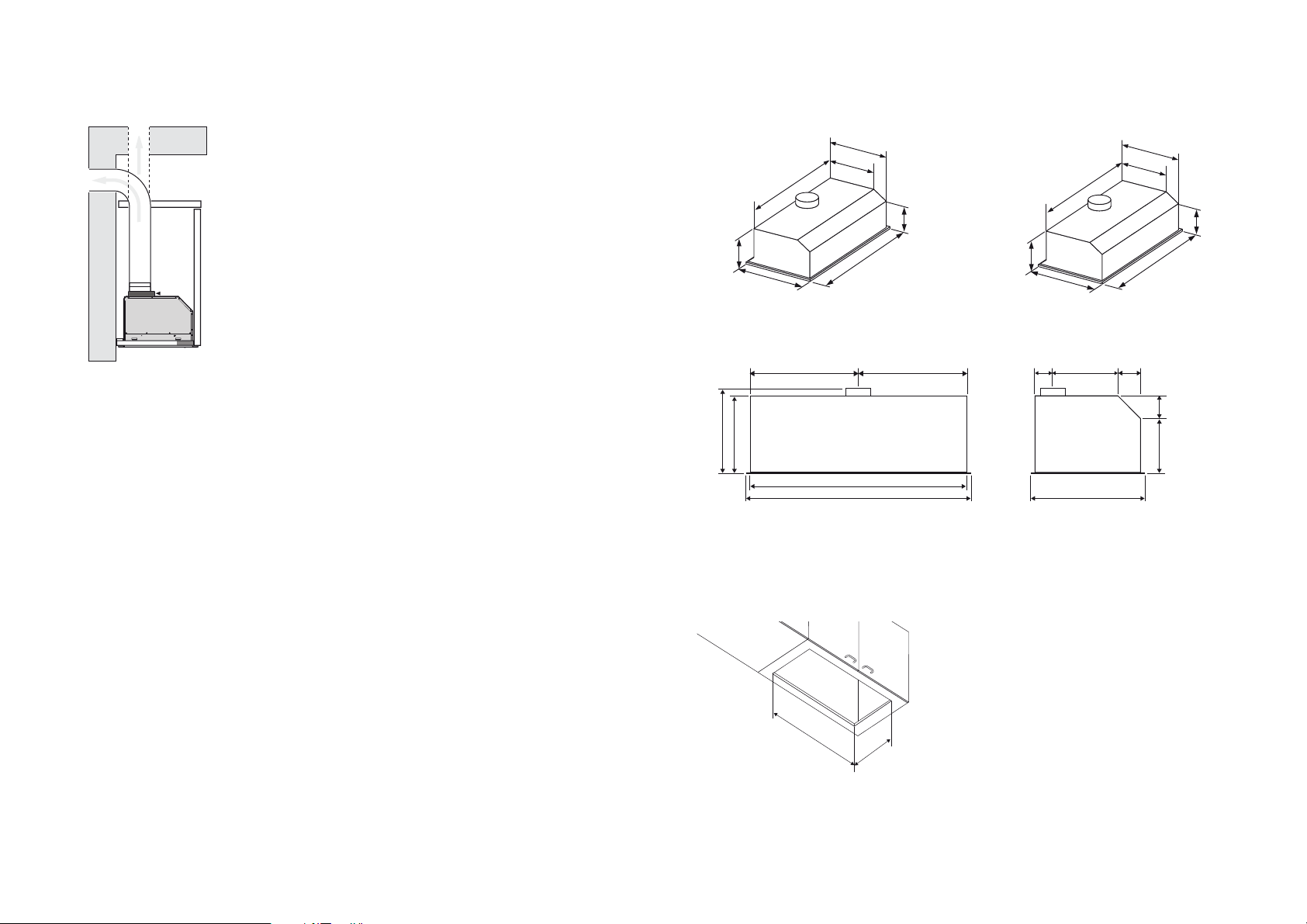
opmerkingen vooraf
De installatie van een afzuigkap moet geschieden in
overeenstemming met de nationaal en lokaal geldende
voorschriften. De afstand tussen de onderzijde van de
afzuigkap en de kookplaat dient minimaal 65 cm te zijn.
Dit toestel dient door een erkend installateur te worden
aangesloten. Schade ontstaan door verkeerd aansluiten of
verkeerd inbouwen valt niet onder de garantie.
attentie:
Door een onjuiste aansluiting van een afzuigkap ontstaat er
extra luchtweerstand waardoor de afzuigcapaciteit afneemt
en de geluidsproductie van de afzuigkap zal toenemen.
- Controleer bestaande kanalen op diameter,
vernauwingen en of deze niet in verbinding staan met
andere kanalen of ruimtes.
- Vermijd vernauwingen en haakse bochten, maar maak
gebruik van afgeronde bochten voor een goede
luchtgeleiding.
- Gebruik gladde kanalen met een inwendige diameter
gelijk aan de uitwendige diameter van de uitblaastuit van
de ventilatorunit.
- Het gebruik van flexibele afvoerslang dient tot een
minimum te worden beperkt en uitsluitend toegepast te
worden voor het maken van kleine overbruggingen.
let op:
Wanneer een afzuigkap en een warmtebron (bijv. gas-, olie-
of kolengestookte fornuizen) die lucht uit dezelfde ruimte
verbruiken tegelijk worden ingezet, bestaat de mogelijkheid
dat de afzuigkap de noodzakelijke verbrandingslucht uit de
ruimte afzuigt waardoor een onderdruk in de ruimte kan
ontstaan. De maximaal toegestane onderdruk bedraagt 4 Pa,
opdat er geen verbrandingsgassen van de warmtebron
worden teruggevoerd naar de ruimte zelf. Daarom is een
luchttoevoer noodzakelijk, waarmee de ruimte constant van
verse lucht wordt voorzien.
elektrische aansluiting
Na montage van de afzuigkap dient de stekker bereikbaar te
zijn of dient de afzuigkap door middel van een dubbelpolige
schakelaar met contactopeningen van 3 mm spanningsloos
te maken te zijn.
Let er bij het aansluiten van de elektrische verbindingen op
dat de contactdoos geaard is en dat het voltage en
frequentie overeenkomt met de op het gegevensplaatje
aangegeven waarden.
Wanneer het aansluitsnoer beschadigd is moet het
vervangen worden door de serviceafdeling van de fabrikant
of gelijkwaardig gekwalificeerde personen om gevaarlijke
situaties te voorkomen.

NL 13NL 12
WU9011PM: 411 x 827 mm
WU1211PM: 411 x 1132 mm
1127
1162
468
292
406
320
206
montage
822
406
320
857
206
468
292
WU9011PM
inbouwmaten
WU11PM
NL 12
installatie (vervolg)
afvoer naar buiten
De afvoer mag in geen geval op een kanaal worden
aangesloten dat ook in gebruik is voor andere doeleinden.
Denk aan de plaatselijk geldende voorschriften met
betrekking tot de beluchting van gasapparaten.
De afvoer kan rechtstreeks door de muur naar buiten
plaatsvinden, mits de muuropening door een rooster wordt
beschermd tegen inregenen en het binnendringen van
bladeren en dergelijke. De doorlaat van de afvoer mag niet
meer dan 20% beperkt worden door het muurrooster.
Wij adviseren een zo ruim mogelijk afvoerkanaal te plaatsen.
Een kleinere diameter heeft een lagere afzuigcapaciteit en
een hoger geluidsniveau tot gevolg. Een bocht geeft
weerstand. Zorg ervoor dat het kanaal vloeiend verloopt en
zo min mogelijk bochten heeft. Trek de flexibele buis zover
mogelijk uit. Controleer voordat u met boren begint of er
geen installatieleidingen aanwezig zijn.
De afvoerstomp heeft een diameter van 150 mm. Het beste is
de afvoerpijp ook met deze diameter uit te voeren. Er wordt
een verloop van 150 mm naar 125 mm bij het toestel geleverd
voor aansluiting op een 125 mm afvoerpijp.
zaagmaten
411
827 (WU9011PM)
1132 (WU1211PM)
321
822 (WU9011PM) - 1127 (WU1211PM)
857(WU9011PM) - 1162 (WU1211PM)
292
468
206 86
86306
100
411 (WU9011PM)
563 (WU1211PM)
411 (WU9011PM)
563 (WU1211PM)

NL 15
technische gegevens
typenummer : zie gegevensplaatje in de kap
energiesoort: 230 V - 50 Hz
aansluitwaarde: zie gegevensplaatje
afmetingen (h x b x d): zie “inbouwmaten”
Dit toestel voldoet aan de geldende CE richtlijnen.
NL 14
montage
inbouwen
1. Verwijder de 4 schroeven (A) en de beugels (B).
2. Schuif de afzuigkap in het keukenkastje / de
zelfbouwschouw. Draai de schroeven (C) aan, zodat de
afzuigkap wordt vastgeklemd door de beugels (D).
3Zet de beugels (H) weer vast met de schroeven (E).
Tip: Laat bij installatie voldoende stroomkabel vrij, zodat de
plafondunit in geval van service gedemonteerd kan worden.
A
B
B
C
D
Min. 12,5 mm
Max. 26 mm
CD
D
afvoeren verpakking en toestel
Bij de vervaardiging van dit toestel is gebruik gemaakt van duurzame materialen.
De verpakking van het toestel is recyclebaar. Gebruikt kunnen zijn:
■karton;
■papier;
■polyethyleenfolie (PE);
■CFK-vrij polystyreen (PS-hardschuim);
■polypropyleenband (PP).
Deze materialen op verantwoorde wijze en conform de overheidsbepalingen afvoeren.
Op het typeplaatje is het symbool van een doorgekruiste vuilnisbak aangebracht:
Dit betekent dat het apparaat aan het einde van zijn levensduur niet bij het gewone
huisvuil mag worden gevoegd, maar naar een speciaal centrum voor gescheiden
afvalinzameling van de gemeente moet worden gebracht of naar een verkooppunt dat
deze service verschaft.
Het apart verwerken van een huishoudelijk apparaat zoals deze afzuigkap voorkomt
mogelijk negatieve gevolgen voor het milieu en de gezondheid die door een
ongeschikte verwerking ontstaat en zorgt ervoor dat de materialen waaruit het
apparaat bestaat teruggewonnen kunnen worden om een aanmerkelijke besparing van
energie en grondstoffen te verkrijgen.
Om op de verplichting tot gescheiden verwerking van elektrische huishoudelijke
apparatuur te wijzen, is op het product het symbool van een doorgekruiste vuilnisbak
aangebracht.

GB 1
table of contentsintroduction
When you have read this manual, you will
quickly be aware of all the facilities the
appliance can offer you. You can read about
safety and how you should look after the
appliance. In addition you will find
environmental tips and instructions that can
help to save energy.
Keep the manual. Any later user of this
appliance could benefit from them.
general 1 - 2
introduction 1
for your safety 2
instructions for use 3 - 7
lighting 3
fan 3 – 5
switch off the key signal 6
faults 7
how to keep the appliance looking good 8 – 9
installation instructions 10 - 15
installation 10 – 12
assembly 13 - 14
technical data 15
disposal of packaging and appliance 15
NL 16
foreword
The extractor hood has been designed for
domestic use and for the purposes stated. Atag
extractor hoods are available in many different
models, which fit elegantly into all interiors.
The ATAG range offers various types of hoods,
some with built-in motors and others suitable
for recirculation.

GB 3GB 2
for your safety
please note
This appliance should be connected by a
registered fitter. Damage arising from incorrect
connection or incorrect fitting is not covered by
the guarantee.
Disconnect the appliance before starting with
cleaning or reparation. It is recommended that
you do this by removing the plug from the
socket or by setting the isolation switch to zero.
Never flambe under an extractor. The high
flames can cause fire. Even if the ventilator is
switched off.
When deep-frying, always keep a close watch.
If the appliance is used together with
equipment which uses gas or other fuels, then a
sufficient supply of fresh air must be ensured.
Switch the extractor hood on before starting to
cook. After cooking, allow the extractor hood to
continue to run for approx. 10 minutes. This can
also be done automatically (see 'automatic
continued running').
Clean the appliance regularly, as shown in
'maintenance'. This minimises the chance of a
fire starting.
Switch off the electricity before replacing the
light bulbs! Only use the same sort of light bulbs
with the same Wattage.
control panel
The LEDs on the control panel light up green in order to
show the programmed setting. The LEDs light red in order to
indicate that the fat filters must be cleaned (see page 9
“cleaning fat filters”) or the carbon filters (optional) must be
changed (see page 9 ”replacing carbon filters”).
switching lighting on and off
Briefly press the lighting button .
The lighting comes on at its highest setting.
Press the key once again and keep it pressed in order to set
the intensity of the lighting. The lighting changes from the
brightest to dimmest setting and vice versa, for as long as
you keep the key pressed.
Press the button for a third time and the lighting goes
out.
switching on the fan
Press the button .
The extractor hood comes on at setting 1. The green LEDs
on the control panel indicate the programmed settings.
adjusting the extractor capacity
Press the button or to select a higher or lower
setting.
OFF
ON
ON
OFF ON 12h
fan
lighting

GB 5GB 4
intensive setting
Press button for a minimum of 2 seconds.
The extractor hood switches to its highest setting for 10
minutes (setting 4). In the control panel the 4th green LED
flashes.
After 10 minutes the extractor hood switches back to the
original setting.
switching off the fan
Repeatedly press the key until all green LEDs in the
control panel are off or press key for at least 2
seconds in order to switch off the extractor hood.
automatic continued operation
Choose the fan setting desired and press button .
The extractor hood remains at the selected setting for 10
minutes, after which the extractor hood is automatically
switched off.
If the lighting was switched on during the automatic
continued running, it will remain switched on. The lighting
will be automatically dimmed to 30-40% of the maximum light
strength.
Press button again to switch off the extractor hood.
12h
12h
OFF
OFF
ON
fan (continued)
OFF ON 12h
fan (continued)
Clean Air function
You can use the Clean Air function to regularly freshen the
air in your residence.
During the Clean Air function, every hour the extractor hood
operates for 10 minutes on setting 1. It then remains
switched off for 50 minutes. This cycle repeats for 12 hours.
Press button for about 4 seconds to switch on the
Clean Air function. The 4th green LED in the operational panel
flashes for as long as setting 1 is switched on (duration 10
minutes). The 4th green LED is permanently lit in the switched
off phase (duration 50 minutes).
After 12 hours the Clean Air function is automatically
switched off. Press button for about 4 seconds to
switch off the Clean Air function after a shorter period.
Attention: if you switch on the extractor hood during use of
the Clean Air function, the Clean Air function will be
cancelled and the extractor hood will continue to operate on
the programmed setting.
grease filter indicator
If the 1st red LED in the control panel starts to flash, clean the
filter immediately.
Replace the cleaned filter and erase the electronic memory
by pressing the button for approx. 5 seconds.
The 1st red LED stops flashing.
OFF
12h
12h
OFF ON 12h

GB 6
solution
Change the light bulb (see
page 8 “Changing the light
bulbs”).
NB:
Only use the same type of lamp
with the wattage stated.
Change the discharge duct
(see installation instructions).
Phone the Service department.
cause
Lamp defective.
Discharge duct too long or has
too many bends.
Motor defective.
Motor or controls defective.
Connection lead defective.
fault
Lighting does not work.
Extractor hood makes a lot of
noise.
No extraction.
GB 7
faults
Please check the following points which may solve the problem, before calling the service
department.
If the connection cable is damaged, it should be replaced by the service department of the
manufacturer or similarly qualified persons in order to prevent dangerous situations from arising.
NNBB::Disconnect the appliance from the mains before starting any repairs, preferably by removing
the plug from the socket or by setting the isolation switch to zero.
switch off the key signal
As you press a key, a key signal sounds in confirmation.
Press keys en for 3 seconds continuously on
the in order to switch on the key signal.
Repeat this procedure if you wish to switch off the key
signal again.
12h
ON
OFF ON 12h

maintenance (continued)
removing/replacing grease filters
Remove the filters as follows: switch the fan and the lighting
off. Take hold of the grease filter by the handle and pull it
down from the lock.
The filter can only be put back into place in one way. Take
note of the correct position of the filter (see illustration).
Hold the filter in such a way that the handle is at the back of
the hood.
Put the filter back into place by first pushing the front side
into the hood. Tilt the rear side up and click the filter into the
lock. The filter is now once again in place. Erase the
electronic memory by pressing the button for approx.
5 seconds.
cleaning the grease filters
You can clean the grease filters in the dishwasher. Allow the
filter to drain well - through the slits in the side - before
putting it back.
OFF
GB 8 GB 9
maintenance
extractor hood
Clean the grease filters as soon as the grease filter indicator
light comes on.
The stainless steel on the outside of the hood can be
cleaned with soapy water and a damp cloth. The stainless
steel will regain its shine if you occasionally use a stainless
steel care product or polish. The polish imparts a dirt-
resistant layer to the stainless steel. Always clean the
stainless steel in the direction of polishing.
Never use abrasive cleaning agents (such as green scouring
pads or other scourers) or polishing cleaning products (such
as liquid scourers).
Never use caustic cleaning agents. These can cause
stainless steel to discolour.
changing the light bulbs
Pull the light bulb (B) down a little and loosen connector (A).
Press the spring (C) in a little and loosen the light bulb (D)
from the casing (E).
Put in a new light bulb with the same wattage and fit it in the
opposite order.
E

GB 11
installation (continued)
NB:
If an extractor hood and a heat source (for example, gas-,
oil- or coal-fired cookers) which take air from the same
room are in use at the same time, there is a possibility that
the extractor hood will cause an underpressure in that room.
The maximum permitted underpressure is 4 Pa, so that no
combustion gases from the heat source can find their way
back into the room. For this reason, an air supply is required
to provide a constant supply of fresh air to the room.
electrical connection
The extractor hood's plug should be accessible after fitting
or the extractor hood should be isolated by a bipolar switch
with 3 mm plug pins.
When making the electrical connections, make sure that the
socket is earthed and that the voltage and frequency
correspond to the values given on the data plate.
If the connection cable is damaged, it should be replaced by
the service department of the manufacturer or similarly
qualified persons in order to prevent dangerous situations
from arising.
GB 10
installation
some preliminary remarks
An extractor hood should be installed in accordance with
national and local regulations. The minimum distance
between the underside of the extractor hood and the hob
should be 65 cm.
The appliance should be connected by a registered fitter.
Damage arising from incorrect connection or incorrect
fitting is not covered by the guarantee.
attention:
When the extractor hood is incorrectly connected, extra air
resistance occurs. This results in a decrease in suction
capacity and the noise production of the extractor hood
increases.
- Check the diameter of existing ducts, check for
blockages and if they are not connected with other
ducts or spaces
- Avoid constriction and angled bends, but instead use
rounded curves for good air conducting.
- Use smooth ducts with the same internal diameter as the
external diameter of the exhaust of the extractor hood.
- The use of flexible piping must be kept to a minimum and
be used exclusively for making short bridging
connections.

1127
1162
468
292
406
320
206
822
406
320
857
206
468
292
WU9011PM WU11PM
GB 13GB 12
assembly
building-in dimensions
installation (continued)
discharge to the outside
The discharge should not be connected to a duct which is
also used for other purposes under any circumstances.
Bear in mind any local regulations concerning the ventilation
of gas appliances.
The discharge may pass straight through the wall to the
outside, provided that the wall opening is protected - by
means of a grating - against rain, leaves, and the like getting
in. The passage of the discharge may not be restricted by
the wall grating by more than 20%.
We advise the use of as large a discharge duct as possible.
A duct with a smaller diameter will have a low extraction
capacity and produce higher noise levels. Bends produce
resistance. Make sure that the duct has a smooth run and
has as few bends as possible. Draw the flexible pipe out as
far as possible. Before starting to drill, check that there are
no installed pipes present.
The discharge stump has a diameter of 150 mm. It is best if
the discharge pipe also has this diameter.
A reducing piece (150 mm to 125 mm) is supplied with the
appliance for connection to a 125 mm discharge pipe. WU9011PM: 411 x 827 mm
WU1211PM: 411 x 1132 mm
cut out dimensions
411
827 (WU9011PM)
1132 (WU1211PM)
321
822 (WU9011PM) - 1127 (WU1211PM)
857(WU9011PM) - 1162 (WU1211PM)
292
468
206 86
86306
100
411 (WU9011PM)
563 (WU1211PM)
411 (WU9011PM)
563 (WU1211PM)

GB 15GB 14
assembly
disposal of packaging and appliance
The packaging of this appliance is recyclable and could be
made of:
■cardboard;
■polythene (PE) film;
■CFC-free polystyrene (PS – hard foam).
These materials are to be disposed of responsibly and in
accordance with government regulations.
To draw attention to the obligation to process electrical
household appliances separately, the product carries the
symbol of a dustbin with a cross through it:
This means that at the end of its working life the product
may not be disposed of as household waste, but must be
taken to a segregated waste collection centre run by the
local authorities or to a dealer providing this service.
Processing household appliances such as this hob
separately prevents negative impacts on the environment
and public health, which might otherwise result from
inappropriate processing.
It also enables the recovery of materials used in the
production of the appliance, thus realising considerable
savings in terms of both raw materials and energy.
technical data
type number: see data plate in the hood
power supply: 230 V - 50 Hz
connected load: see data plate
dimensions (h x w x d): see "fitting dimensions"
This appliance complies with the CE directives.
building-in
1. Remove the 4 screws (A) and the brackets (B).
2. Slide the extractor hood into the kitchen cupboard / the
self-assembled mantel. Tighten the screws (C), so that
the extractor hood is clamped by the braces (D).
3Secure the brackets (H) again with the screws (E).
Tip: During installation leave sufficient cable free, so that the
ceiling unit can be dismantled for servicing.
A
B
B
C
D

FR 1
table des matièresintroduction
Ce manuel est un aperçu des possibilités
offertes par cet appareil. Il vous fournira des
renseignements précieux sur le plan de la
sécurité et de l'entretien ainsi que des conseils
en matière d'environnement et d'économie
d'énergie.
Conservez le manuel et les directives
d'installation. Ainsi, un éventuel prochain
usager de l'appareil pourra en profiter.
généralités 1 - 2
introduction 1
sécurité avant tout 2
manuel 3 - 7
éclairage 3
ventilateur 3 – 5
désactiver le signal sonore 6
anomalies de fonctionnement 7
entretien 8 – 9
directives d'installation 10 - 15
installation 10 – 12
montage 13 - 14
données techniques 15
élimination de l’emballage et appareil 15
préface
La hotte a été conçue pour répondre à un
usage ménager et aux objectifs indiqués. Les
hottes ATAG se présentent sous divers modèles
qui se combinent à merveille avec tout type
d'intérieur.
L'assortiment comprend divers types de hottes
avec moteur encastré ou externe et des
modèles appropriés pour la recirculation.

FR 3FR 2
sécurité avant tout
points d'attention
Le branchement de l'appareil doit être fait par
un installateur agréé. La garantie ne couvre pas
les dommages causés par un branchement
erroné.
Avant de réparer ou de nettoyer l'appareil,
couper le courant. De préférence, débranchez
la prise ou mettez l’interrupteur sur zéro.
Ne jamais faire flamber de préparation sous la
hotte aspirante. Les flammes élevées risquent
de provoquer un incendie. Même si le
ventilateur est éteint.
Il est recommandé de rester sur place et
surveiller la friture.
Si l'appareil est utilisé combiné à un appareil
fonctionnant au gaz ou avec un autre
combustible, veillez à une admission d'air frais
suffisante.
Actionnez la hotte avant de commencer la
cuisson. Après cuisson, attendez encore 10
minutes environ avant d'arrêter la hotte. Ceci
peut se faire automatiquement (voir "fonction
arrêt différé à durée préprogrammée").
Nettoyer l'appareil régulièrement, comme
indiqué dans "entretien". Ceci évite les risques
d'incendie.
Avant de changer une ampoule, toujours
débrancher l'appareil! N'utiliser que des
ampoules semblables à celles d'origine et avec
le même voltage.
panneau de commande
Les LED sur le panneau de commande s’allument en vert
pour indiquer la position. Ils s’allument en rouge pour
indiquer que les filtres ont besoin de nettoyage (voir page 9
“nettoyer les filtres”) ou qu’il faut remplacer les filtres à
carbone (optionnels) (voir page 9 “remplacer le filtres à
carbone”).
mise en/hors service de l'éclairage
Appuyez sur la touche pour l'éclairage.
L'éclairage va s'enclencher sur la position maximale.
Appuyez à nouveau sur la touche et maintenez-la enfoncée
pour régler l’intensité de l’éclairage. L’éclairage varie de la
position la plus élevée du graduateur vers la position la plus
basse, aussi longtemps que vous maintenez la touche
enfoncée.
Appuyez une troisième fois sur la touche pour
éteindre la lumière.
mise en service du ventilateur
Appuyez sur la touche .
La hotte se met en marche sur la position 1. Les LED verts du
panneau de commande indiquent la position réglée.
réglage de la capacité d'aspiration
Appuyez sur la touche ou pour une position
plus élevée ou plus basse.
OFF
ON
ON
OFF ON 12h
ventilateur
éclairage
This manual suits for next models
1
Table of contents
Languages:
Other Atag Ventilation Hood manuals

Atag
Atag WU70211RM User manual

Atag
Atag WS9111MR/A01 User manual

Atag
Atag EG411X Technical manual

Atag
Atag WU5011BM Operation manual

Atag
Atag WU11 PM Series User manual

Atag
Atag WI6011CM Operation manual

Atag
Atag WS60 ICR Series User manual

Atag
Atag ws6011pm User manual

Atag
Atag WS902 EM Series User manual

Atag
Atag WS9111FM User manual

Atag
Atag WI60211CM User manual

Atag
Atag CU90554TMM User manual

Atag
Atag WS9211EM User manual

Atag
Atag WV6111AM Operation manual

Atag
Atag WS6111MR User manual

Atag
Atag WU7011GM Operation manual

Atag
Atag WI60211BC User manual

Atag
Atag WS70 DL Series User manual

Atag
Atag WV60 MS Series User manual

Atag
Atag ES1011QAM User manual