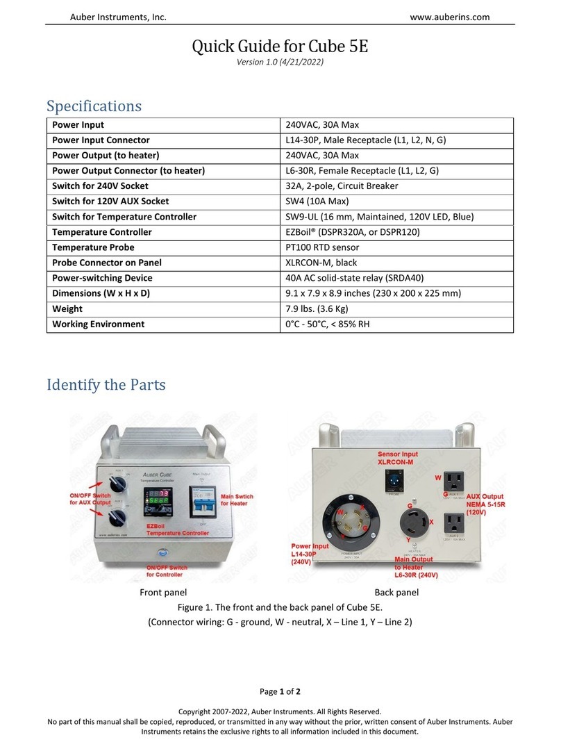
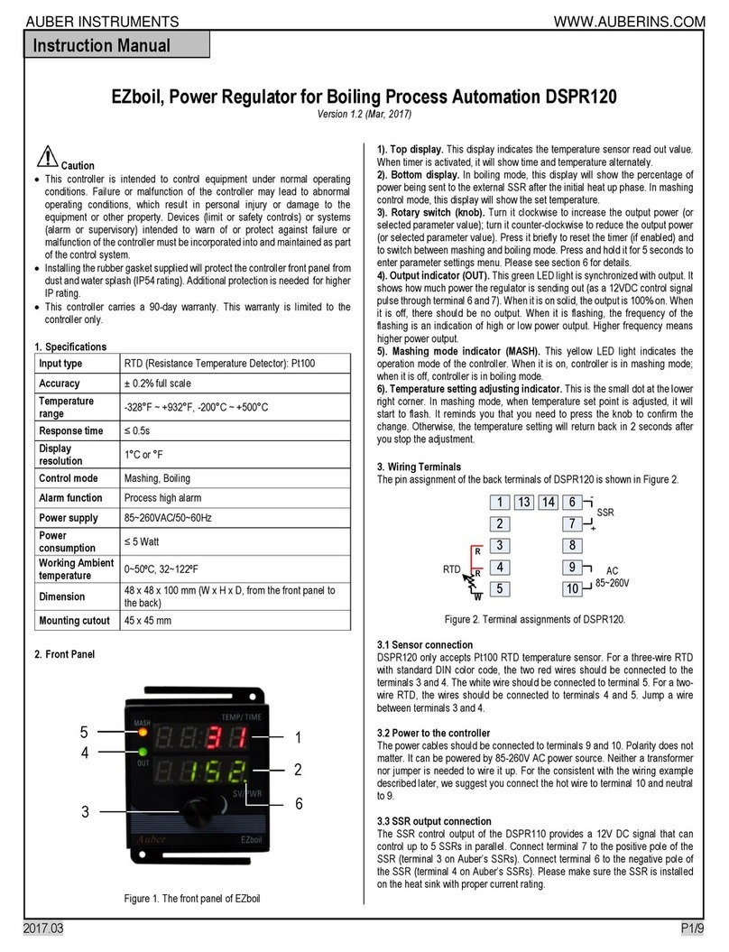
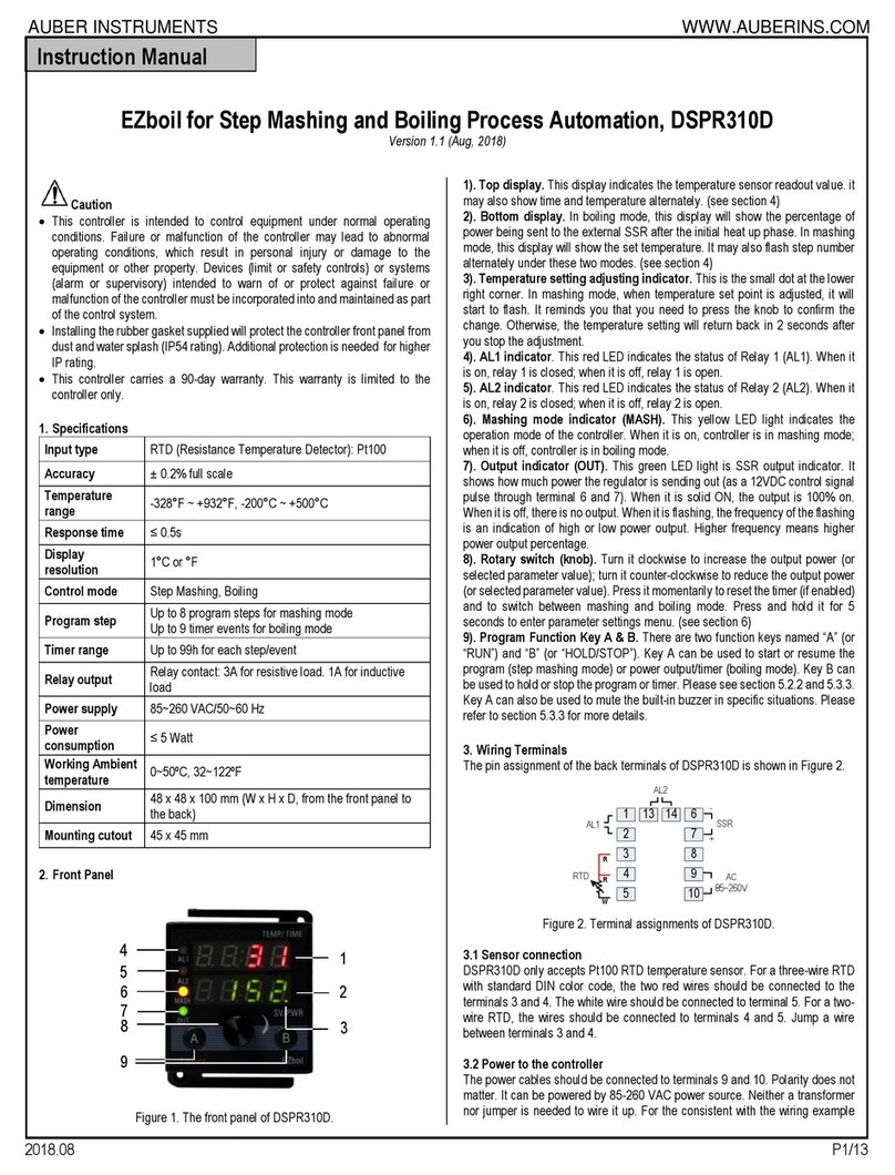
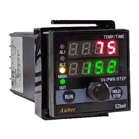
manuals.online logo
Brands
  1. Home
  2. •
  3. Brands
  4. •
  5. Auber Instruments
  6. •
  7. Controllers
  8. •
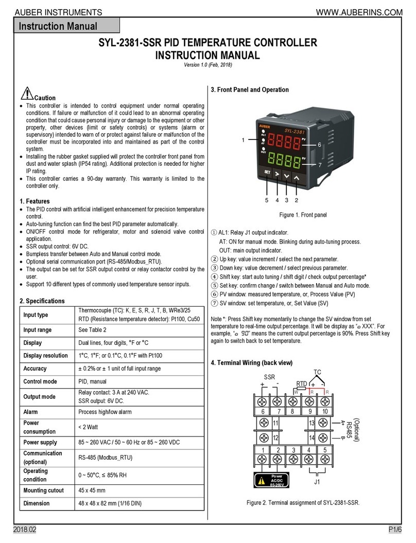
  9. Auber Instruments SYL-3615 User manual

Auber Instruments SYL-3615 User manual

AUBER INSTRUMENTS WWW.AUBERINS.COM
2020.11 P1/5
SYL-3615 Wi-Fi BBQ Controller Quick Guide
Firmware v0.9.77
Document version 0.9.1 (Nov, 2020)
Caution
•This controller is intended to control equipment under normal operating
conditions. If failure or malfunction of the controller may lead to abnormal
operating conditions that may result in personal injury or damage to the
equipment or other property, devices (limit or safety controls) or systems
(alarm or supervisory) intended to warn of or protect against failure or
malfunction of the controller must be incorporated into and maintained as
part of the control system.
•This controller carries a one (1) year warranty. This warranty is limited to
the controller only.
1. Front Panel and Connections on SYL-3615
6. Wi-Fi indicator
7. Output indicator
8. Pit probe
9. Food probe
10. Probe 3
1. LCD display
2.SET key
3.TIMER/BACK key
4.Down key
5.Up k ey
12.Power adapter
connector
11.Fan connec tor
Figure 1. Front panel of a SYL-3615 controller.
17. Power-in socket
16. Output sock et (fan)
15. P3 port (probe 3)
14. P2 port (food)
13. P1 port (pit)
Figure 2. Connection ports on the bottom of a SYL-3615.
Table 1. Recognize different parts on a SYL-3615.
#
Name
Description
1
LCD display
Display probe readings, set temperature, and etc.
2
SET key
* Short-press to access cooking profile menu.
* Long-press to access control menu and system
menu.
3
TIMER /
BACK key
* Check status (step number, time, and output).
* Cancel Open-lid status.
4
DOWN key
* Mute the buzzer.
* Scroll down the menu.
* Decrease value.
5
UP key
* Scroll down the menu.
* Decrease value.
6
Wi-Fi indicator
* Solid-on, connected to Wi-Fi.
* Slow-blinking, lost Wi-Fi connection.
* Fast-blinking, ready to pair (AP mode).
7
Output
indicator
Indication of the output level to the fan.
8
Pit Probe
The probe that measures pit temperature
9
Food Probe
A pointed probe can be inserted into food.
10
Probe 3
A third probe for monitoring food temperature.
11
Fan connector
DC connector from the fan, 2.5 mm x 5.5 mm.
12
Power
adapter
connector
DC connector, 2.1 mm x 5.5 mm. Supplies 12
VDC from the power adapter.
13
P1
Sensor port for the pit probe.
14
P2
Sensor port for the food probe.
15
P3
Sensor port for the third probe.
16
Output to Fan
Output port for the fan, 2.5 mm x 5.5 mm.
17
Power-in
Power input socket, 2.1 mm x 5.5 mm.
2. Getting started
2.1. Powering up the device
Simply connect the 12 VDC power adapter to a wall outlet and then plug
the barrel connector (2.1 mm x 5.5 mm) to the power-in socket on the
very left port on the bottom of the SYL-3615 controller (see Figure 2).
The controller’s LCD screen should light up and show its model number
and the firmware version (Figure 3a), and then the LCD screen will go to
the normal display mode (Figure 3b). The “-H-“ is a sensor error code,
which means no probe is connected or detected.
Instruction Manual
AUBER INSTRUMENTS WWW.AUBERINS.COM
2020.11 P2/5
SYL-3615
v0.9.77
Figure 3(a). The display screen when controller is just powered up.
Pit: -H- Set: 225
Food: -H- P3: -H-
Figure 3(b). The display screen in normal operating mode.
2.2. Connecting probes
Plug the pit probe to P1 port, the food probe to P2 port, and the third
probe to the P3 port. The screen should show the readings from each
probe in the specific area as shown in Figure 3 below.
Pit: 78 Set: 225
Food: 77 P3: 77
Pit probe reading
Food probe reading Probe 3 reading
Set temperature
Figure 4. A SYL-3615 shows readings from all three probe and the
set-temperature.
2.3. Plugging in the fan
Plug the barrel connector from the fan (2.5 mm x 5.5 mm) to the second
port from the left, which is marked as FAN (see Figure 2).
2.4. Getting familiar with different display modes
From the normal operating mode, the user can go to other display modes to
check the status by going to the time-checking mode, editing the cooking
profile, or change settings. The diagram below shows how to switch to other
display modes.
Pit: 78 Set: 225
Food: 77 P3: 77
>P-Status: Step-1
Step: 1 Pit: 225
Step 2 Run 0:05
Ends at Temp 0
>Control Setting
System Config
Total Run 10:05
Power Output 100
Cooking Profile
Menu
Normal Operating Mode Time-checking
Hold f or 2
seconds
SET
SET
/
/ /
Page 2
Page 1
Figure 5. Switching to different display modes.
a) Checking status: time-checking mode.
Press the TIMER/BACK key to check the current step number, step time, and
the ending-criteria. Press the TIMER key one more time to check the total
cooking time and the output percentage to the fan. Press the TIMER key again
to return to the normal display mode.
b) Editing the cooking profile: cooking profile settings.
Press the SET key briefly to enter the Cooking Profile Setting Mode.
c) Accessing control settings and system configurations.
Press and hold down the SET key for 2 seconds to bring up the Control
Setting and System Configuration menus.
3. Pairing a SYL-3615 to a Wi-Fi Router
Important: The Wi-Fi chip in SYL-3615 can only connect to 2.4 GHz Wi-Fi
signal. Please make sure your router has 2.4 GHz Wi-Fi.
3.1. Download and install the lastest AuberSmart App
3.2. Set the controller to Access Point (AP) mode
Only when the device is in the Access Point (AP) mode, can it be paired
to your home router. When you receive a new SYL-3615 from
Auberins.com, the unit should be in the Wi-Fi pairing mode. The Wi-Fi
status indicator (blue LED) should be fast-blinking.
To manually change the device to Wi-Fi pairing mode, press and hold
SET key for 2 seconds to bring up the menu, and go to “System Config”
sub-menu. Then scroll down to find “Reset WiFi” and select “Yes”. The
device will reset to AP mode and re-start.
3.3. Pair the SYL-3615 to a wireless router
a) Please make sure your phone is connected to a 2.4 GHz Wi-
Fi signal from your router.
Note: This step is important because our App will need to acquire the Wi-Fi
name (SSID) and send it to the SYL-3615 in a later step.
b) Open the AuberSmart App, tap on “add a device” button.
c) Enter the Wi-Fi password and tap on the orange “Connect
SYL-3615” button.
Note: This button is dedicated to adding SYL-3615 whose Wi-Fi pairing
process is different from Auber’s first-generation Wi-Fi devices.
d) Please read the pop-up message boxes and tap “CONTINUE”
till the App will take you to the Wi-Fi Setting page of your
phone.
e) On the list of the available Wi-Fi signals, select the one starts
with “AuberSmart” and a series of numbers and letters. This
Wi-Fi signal is generated by SYL-3615 for pairing purpose.
No password is needed.
f) Once connected the “AuberSmart” Wi-Fi signal, click the
“Continue” button on the lower-right corner.
g) The next pop-up message box will ask you to confirm that
your phone has connected to the Wi-Fi signal generated by
the SYL-3615. Tap CONFIRM to go ahead with the paring
process.
AUBER INSTRUMENTS WWW.AUBERINS.COM
2020.11 P3/5
Important tip: Your phone may recognize that the wireless signal from SYL-
3615 has “no internet access” and may want to switch to use mobile data or a
different Wi-Fi signal. If your phone prompts such a notification bar on the top
of the screen, please tap on it and select YES to stay connected.
h) Once you tap on the CONFIRM button, the SSID and
password will be sent to the SYL-3615 so that it can log on to
your 2.4 GHz Wi-Fi.
i) If the pairing process is successful, the SYL-3615 will re-start
and the blue LED will turn to solid-on. That means the device
has been connected to your router. In the meantime, the App
will return to the Device List page and a new SYL-3615 will
appear on this page.
j) If the pairing process is unsuccessful, the App will remain on
the Add Device page. Please try again, and making sure you
check if the SSID is the desired wireless signal you want to
connect, if the password is correct, and wait a little bit long at
step (g) till the “no internet access” notification appears.
4. Programming a cooking profile
4.1. Single-step mode
By factory default setting, the SYL-3615 is initially set a single-step mode
with set-temperature at 225° F, which means the controller will try to
maintain pit temperature at 225° F indefinitely.
Note: In single-step mode, the Start and Stop function in the “P-Status”
(Program Status) parameter do NOT work.
To change the set temperature in single-step mode, short-press the SET
key on a SYL-3615 to bring up the cooking-profile menu. Move the
cursor to “Step:1” and press SET key to enable editing the value. When
finished editing the set value, press SET key again to save the value.
Press the BACK key to return to the normal operating mode.
P-Status: Step-1
>Step: 1 Pit: 225
Figure 6. Move the cursor to Step 1 to edit the set value in the
single-step mode.
4.2. Enable multi-step mode
To enable the multi-step cooking profile, please go to the System
Configuration menu and change the parameter PRG to ON.
>PRG: ON
OL Detect ON
Figure 7. Change PRG to ON to enable the multi-step mode.
4.3. Multi-step cooking profile
You can program up to 6 steps in a cooking profile. In each step, there
are 4 parameters involved in this step: pit temperature, ending criteria,
step timer, or food temperature. The table below describes how the
settings in each parameter affects execution of a cooking step. The chart
in Figure 8 describes how the parameters in a cooking steps affects the
cooking process.
Name
Range
Description
Pit
-99°F~ 999°F
The set value of pit temperature of the current
step.
Ending
Food Temp
To end the current step when food probe
reading reaches a desired temperature.
Time
To end the current step by cooking time.
End
To end the entire cooking. The rest of steps in
this cooking profile will be ignored.
Timer
0:00 ~ 23:59
(hh:mm)
Cooking time, if the current step will end by
“Time”.
Food
-99° F ~ 999° F
Target food temperature, if the current step
will end by food temperature.
Ending?
Pit
Timer Food
Step x
Step (x+1)
Start
End
Determine the desired pit
temperature of this step
How do you want to end
this step?
Cooking
Time
Food
Temp.
End the
program
Enter step
time or
target food
temp.
Figure 8. Flow chart on how the parameters of a cooking step
works.
AUBER INSTRUMENTS WWW.AUBERINS.COM
2020.11 P4/5
5. Accessing the menus
To access the menus, press and hold the SET key for 2 seconds.
5.1. Control Setting
Name
Description
Range
Initial
Note
Pit-AH
Pit High Alarm
0 ~ 999
350
1
Pit-AL
Pit Low Alarm
0 ~ 999
50
2
Food-AH
Food High Alarm
0 ~ 999
350
3
Probe3-
AH
Probe 3 High Alarm
0 ~ 999
350
3
P
Proportional
Constant
1 ~ 999
45
4
I
Integral Time
0 ~ 9999
1200
5
D
Derivative Time
0 ~ 999
75
6
T
Control Cycle Time
2 ~ 200
15
7
MODE
Control Mode
Manual-FS,
Manual-TP,
PID-FS,
PID-TP
PID-FS
8
Save
Save PID Settings
(Back), BGE,
WSM22,
WSM18,
4,5,6
Back
9
Recall
Recall PID Settings
(Back), BGE,
WSM22,
WSM18,
4,5,6
Back
9
Back
Back to main menu
5.2. System Configuration
Name
Description
Range
Initial
Note
PRG
Multi-step program
On, off
Off
10
OL
Detection
Open-lid detection
On, off
On
11
FMRV
Minimum running
voltage of the fan
3.0 V ~ 11.0 V
4.0
12
OUTH
Output high-limit
0 ~ 100 (%)
100
13
OUTL
Output low-limit
0 ~ 100 (%)
0
C-F
Temperature unit
° C, ° F
F
14
PB1
Probe 1 offset
-99 ~ 100
0
15
PB2
Probe 2 offset
-99 ~ 100
0
15
PB3
Probe 3 offset
-99 ~ 100
0
15
Buzzer
Enable or disable the
on-board buzzer
On, Off
On
16
nFIL
Powerline filter
A, B, Auto
B
17
Brightness
LCD back-light
brightness
0 ~ 10
10
18
Push
Alarm
Enable pushing
temperature alarms to a
paired mobile device
On, off
On
19
Push Step
Enable pushing step
notifications to a paired
mobile device
On, off
On
20
Reset
Restore all parameters
to factory default values
Yes, No
No
21
Reset
WiFi
Reset Wi-Fi chip to AP
mode (pairing mode)
Yes, No
No
22
Update
Check and update
device firmware
Yes, No
No
23
Back
Back to main menu
6. Using and mounting the controller
6.1. Operating temperature
The operating environment temperature for the meter is from 0°F~
100° F (20° C ~ 50° C). The meter should be placed away from high heat
to protect the plastic housing and electronics. Mount or place the
controller away from the heat from the smoker. Avoid exposing the
controller under directly sunshine during hot summer days.
6.2. Protect the controller from rain
The case is not water-proof. If you want to use under light rain even for a
short period, it’s better to cover the controller with a transparent and
waterproof bag or a container. Please also lift the controller from the
ground or any surface that may cause splashed water get into the case
from the bottom of the controller.
6.3. Mounting hooks
Two mounting hooks and two M4 screws are supplied with the controller.
These hooks can be installed as shown in Figure 9 and 10.
Figure 9. How to install the mounting hooks to SYL-3615.
AUBER INSTRUMENTS WWW.AUBERINS.COM
2020.11 P5/5
Figure 10. Two mounting hooks installed on the back of a SYL-3615
controller.
7. FAQs
7.1. A probe shows “-H-”when it is plugged in.
The “-H-” is a probe input error message, which usually indicates that no
probe is connected or the probe is defective.
7.2. A probe reading appears to be jumping round.
Please swap with another good probe to see if the issue moves with the
probe or stays with the probe socket. If the probe connector is loose, the
wires inside the probe is broken or about to break, the reading may jump
around.
7.3. How to clean the probes.
Do NOT wash the probe. Only wipe the probe’s stainless steel sheath
with damped paper towel or cloth. Please also keep water out of the
probe connector as well.
7.4. Can I leave the controller, the fan, and the probes
on the smoker after each cooking?
No, please do NOT leave them outside on the smoker. After each use,
keep them in a dry and cool environment.
7.5. What if I have one cooking step ends with food
temperature but I have no plugged in a food probe?
If a cooking step’s” ending criteria is food temperature, however, no food
probe is plugged in, the controller will still maintain the pit temperature
but this step will never end.
(End)
Auber Instruments Inc.
5755 North Point Parkway, Suite 99,
Alpharetta, GA 30022
www.auberins.com
E-mail: [email protected] Tel: 770-569-8420
Copyright 2007-2020, Auber Instruments All Rights Reserved.
No part of this manual shall be copied, reproduced, or transmitted in any way without
the prior, written consent of Auber Instruments. Auber Instruments retains the exclusive
rights to all information included in this document.

Other Auber Instruments Controllers manuals

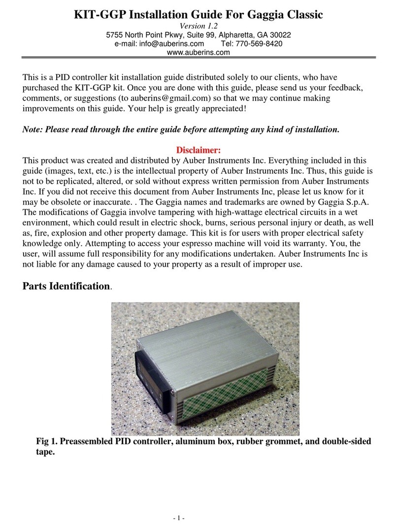
Auber Instruments Auberins KIT-GGP User manual

Auber Instruments

Auber Instruments Auberins KIT-GGP User manual

Auber Instruments KIT-Cube5E User manual

Auber Instruments

Auber Instruments KIT-Cube5E User manual

Auber Instruments EZboil DSPR120 User manual

Auber Instruments

Auber Instruments EZboil DSPR120 User manual

Auber Instruments DSPR300 User manual

Auber Instruments

Auber Instruments DSPR300 User manual

Auber Instruments DSPR400 User manual

Auber Instruments

Auber Instruments DSPR400 User manual

Auber Instruments AUB6500 User manual

Auber Instruments

Auber Instruments AUB6500 User manual

Auber Instruments SYL-3615 User manual

Auber Instruments

Auber Instruments SYL-3615 User manual

Auber Instruments KIT-CUBE2S User manual

Auber Instruments

Auber Instruments KIT-CUBE2S User manual

Auber Instruments WS-1500A Administrator Guide

Auber Instruments

Auber Instruments WS-1500A Administrator Guide

Auber Instruments WS-1500EPM Administrator Guide

Auber Instruments

Auber Instruments WS-1500EPM Administrator Guide

Auber Instruments SYL-2381-SSR User manual

Auber Instruments

Auber Instruments SYL-2381-SSR User manual

Auber Instruments AW-SYL-2352 User manual

Auber Instruments

Auber Instruments AW-SYL-2352 User manual

Auber Instruments TH220A User manual

Auber Instruments

Auber Instruments TH220A User manual

Auber Instruments KIT-RSPb User manual

Auber Instruments

Auber Instruments KIT-RSPb User manual

Auber Instruments SYL-2615 User manual

Auber Instruments

Auber Instruments SYL-2615 User manual

Auber Instruments HD330 User manual

Auber Instruments

Auber Instruments HD330 User manual

Auber Instruments SYL-2362B User manual

Auber Instruments

Auber Instruments SYL-2362B User manual

Auber Instruments EZboil DSPR310D User manual

Auber Instruments

Auber Instruments EZboil DSPR310D User manual

Auber Instruments Cube 5E User manual

Auber Instruments

Auber Instruments Cube 5E User manual
Auber Instruments EZboil DSPR310D User manual
Auber Instruments

Auber Instruments EZboil DSPR310D User manual

Auber Instruments EZboil DSPR320 User manual

Auber Instruments

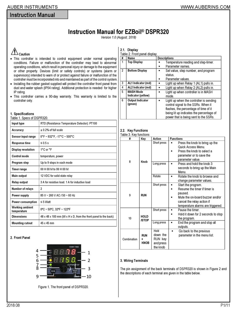
Auber Instruments EZboil DSPR320 User manual

Auber Instruments HD220-W Instructions and recipes

Auber Instruments

Auber Instruments HD220-W Instructions and recipes

Auber Instruments SYL-53 2P Series User manual

Auber Instruments

Auber Instruments SYL-53 2P Series User manual

Auber Instruments EZboil DSPR310 User manual
Auber Instruments

Auber Instruments EZboil DSPR310 User manual

Popular Controllers manuals by other brands

RWE ISR2 quick start guide

RWE

RWE ISR2 quick start guide

Allen-Bradley Bulletin 161 B Series user manual

Allen-Bradley

Allen-Bradley Bulletin 161 B Series user manual

Honeywell CENTRA LINE EAGLEHAWK Installation & commissioning instructions

Honeywell

Honeywell CENTRA LINE EAGLEHAWK Installation & commissioning instructions

Salto BLUEnet CUC1B0 Series installation guide

Salto

Salto BLUEnet CUC1B0 Series installation guide

Vega VEGATOR 111 operating instructions

Vega

Vega VEGATOR 111 operating instructions

HDL Buspro HDL-MSM.431 user manual

HDL

HDL Buspro HDL-MSM.431 user manual

Evco EV3 WEB Installer manual

Evco

Evco EV3 WEB Installer manual

Motorline professional SIGMA X User& installer's manual

Motorline professional

Motorline professional SIGMA X User& installer's manual

DriSteem Vapor-logic 4 Installation and operation manual

DriSteem

DriSteem Vapor-logic 4 Installation and operation manual

Emerson CASH VALVE B Series Installation, operation and maintenance instructions

Emerson

Emerson CASH VALVE B Series Installation, operation and maintenance instructions

Asco WSDU-M Series Installation and maintenance instructions

Asco

Asco WSDU-M Series Installation and maintenance instructions

AUMA SV 05.1 Operation instructions

AUMA

AUMA SV 05.1 Operation instructions

Elan V883 installation manual

Elan

Elan V883 installation manual

Caen V793 Technical information manual

Caen

Caen V793 Technical information manual

Euroterm 2604 Installation and wiring instructions

Euroterm

Euroterm 2604 Installation and wiring instructions

Toshiba Prosec T-Series Operation manual

Toshiba

Toshiba Prosec T-Series Operation manual

Seeley MagIQtouch Original instructions

Seeley

Seeley MagIQtouch Original instructions

JP Hobby ER-120 V1 instruction manual

JP Hobby

JP Hobby ER-120 V1 instruction manual

manuals.online logo
manuals.online logoBrands
  • About & Mission
  • Contact us
  • Privacy Policy
  • Terms and Conditions

Copyright 2025 Manuals.Online. All Rights Reserved.