manuals.online logo
Brands
  1. Home
  2. •
  3. Brands
  4. •
  5. Auber Instruments
  6. •
  7. Controllers
  8. •
  9. Auber Instruments RDK-300B User manual

Auber Instruments RDK-300B User manual

AUBER INSTRUMENTS WWW.AUBERINS.COM
2020.04 P1/2
RDK-300B Controller for Hot Runner Coil Heater
Version 1.0 (April, 2020)
Caution
 Check pin assignment before connecting a coil to the controller (see section
3.4). The pin assignment on RDK-300 is different from RDK-100.
 The default set temperature on RDK-300B is 300°F. The controller will start
to heat the coil immediately after it is power up if coil is connected. Please
make sure the coil is placed in a secure place before power up.
 The coil heater should NOT be heated above 1000°F. By default, the auto-
shutoff temperature and time are set to 900°F and 60 minutes.
 When controller is turned off, the coil will stay at very high temperature for at
least 20 minutes. DO NOT TOUCH the coil until controller stops flashing
“Hot”. The heated coil is very dangerous. It will cause severe burn if touched.
 One (1) year warranty for the controller; six (6) months for the coil heater*
Note: * Our warranty for coil heater only covers manufacturing defects; it does NOT cover
damages caused by high temperature (≥ 1000°F) use.
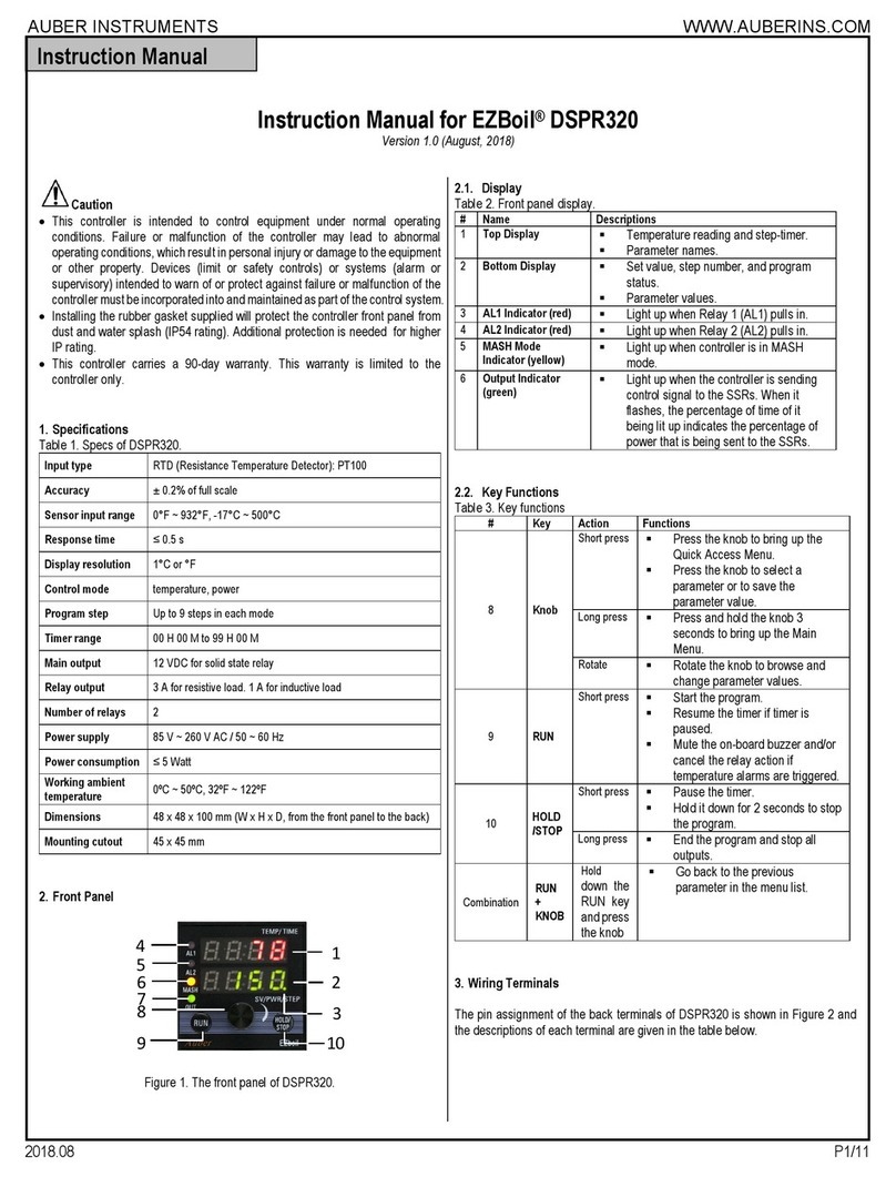
1. Specification
Controller
Operating voltage 120 V / 240 V AC
Maximum current 5 Amp
Input power connection IEC 320 C14
Coil connection XLR 5 Pin
Dimension 3.5 x 1.7 x 4.7 inch, (90 x 47 x 120 mm)
Temperature control range 200°F to 1000 °F
2. Front Panel
①
②
③
④
⑤
Figure 1. Front Panel.
① Current temperature
② Output status indicator
③ Set temperature
④ Power button with stand-by status indicator
⑤ Control knob. Access menu and change parameters
3. Getting Started
3.1 Confirm the Pin Assignment on the Heater Coil
Before you plugging any coil to this controller, please confirm that the coil has
the same pin assignment (see Table 1) as the RDK-300B.
Table 1. Pin Assignment of the XLR connector on RDK-300B.
1 AC Power to Heater
2 AC Power to Heater
3 TC +
4 TC -
5 Ground
3.2 Connecting the Coil Heater
To connect the coil heater, align the slot on the XLR connector on the coil
cable with the tab on the female XLR connector on the controller, and then
push it in. To disconnect it, press the “PUSH” tab on the female connector and
pull the connector out.
Warning: With a coil connected, the controller will start to heat
the coil immediately after it is power up. Please make sure that the
coil is placed in a secure place before power up. When controller is
turned off, the coil will stay at a very high temperature for at least 20
min. Controller will flash “hot” and coil temperature at top display,
and it will show “off” at bottom display. DO NOT TOUCH the coil until
the controller stop flashing “hot”. The heated coil is very dangerous.
It will cause severe burn if touched. It is strongly recommended
that the power cord should be unplugged after use.
3.3 Power On/Off the Controller
Connecting the power cord to the controller and to the wall outlet, then the
power button should light up in red, which means the controller is in standby
status. The displays should still be dark and there should be no power output to
the coil heater. Press down the power button briefly, the display should turn on
and the power button will lit in white. The bottom of the display window will
show the set temperature value, and the top display window will show the
current coil temperature. Controller will start heating up the coil to the set
temperature. If no coil is plugged in, the top display will show “-H-“.
To power off the controller, press down the power button briefly. Controller will
cut off power to the coil, keep displaying the coil temperature till it is cooled
below a safe cool temperature.
3.4 Basic Operations
This controller has two operating mode, standard mode and boost mode
(which is newly added to RKD-300B). By default, the controller will first power
up in standard mode.
Instruction Manual
AUBER INSTRUMENTS WWW.AUBERINS.COM
2020.04 P2/2
3.4.1 Standard Mode
When the controller is powered up in standard mode or switched to standard
mode, the top display will show “std” briefly.
This controller has been programmed for 100 Watt hot runner coil. The set
temperature has been set to 300°F. If you want to change the set temperature,
please follow the steps below:
1) Press down the knob briefly. The decimal point in the lower right corner of
the bottom display will start flashing.
2) Turn the control knob to adjust the set temperature. Turn it clockwise to
increase the value; counter-clockwise to decrease the value. Use fast rotation
action for big adjustment, use slow rotation action for single digit adjustment.
3) Press down the knob again to confirm the new set temperature. The
controller will also exit the editing mode if the knob was untouched for 10
seconds.
3.4.2 Boost Mode
In a boost mode, the user can quickly cycle between two set temperatures, a
lower standby temperature and a higher boost temperature, by simply pressing
down the control knob. There is no need to turn the knob back and forth to
adjust for the desired set temperature.
To switch from the standby temperature to the boost temperature, simply press
down the control knob. The lower display will show the new set temperature,
which is the boost temperature. To switch back to the standby temperature,
press down the knob again.
There are 3 boost modes available, named as “b-1”, “b-2”, and “b-3”. A user
can adjust and save customized standby temperature and boost temperature
for each mode. By default, the standby temperature is 300°F and the boost
temperature is 550°F for all three boost modes.
When the controller is powered up in a boost mode or switched to a boost
mode, the top display will show the name of the boost mode briefly and then
show the coil temperature. The bottom display will show the standby
temperature.
More detailed explanation of the boost mode and the related parameters can
be found in the RDK-300B Supplementary Manual.
3.4.3 Switching Between Standard Mode and Boost Mode
To change the operating mode, turn the control knob in any direction for at
least a half turn (180°) in one action to bring up the mode-selecting menu. The
top window will show “MOD” and the bottom window will show the name of
the current mode. Turn the knob slowly in either direction to browse the options
in the menu and press down the control knob to confirm your selection. The
flashing dot in the lower right corner indicates the item is in editing and has not
been saved yet.
3.5 Advanced Parameter Settings
Please see the RDK-300B Supplementary Manual for more information about
parameters.
(End)
Auber Instruments Inc.
5755 North Point Parkway, Suite 99,
Alpharetta, GA 30022
www.auberins.com
E-mail: [email protected] Tel: 770-569-8420
Copyright 2007-2020, Auber Instruments All Rights Reserved.
No part of this manual shall be copied, reproduced, or transmitted in any way without the prior, written
consent of Auber Instruments. Auber Instruments retains the exclusive rights to all information
included in this document.

Other Auber Instruments Controllers manuals

Auber Instruments KIT-Cube5E User manual

Auber Instruments

Auber Instruments KIT-Cube5E User manual

Auber Instruments HD330 User manual

Auber Instruments

Auber Instruments HD330 User manual

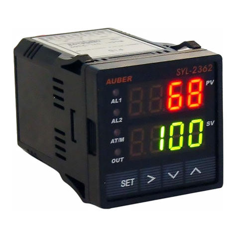
Auber Instruments SYL-2615 User manual

Auber Instruments

Auber Instruments SYL-2615 User manual

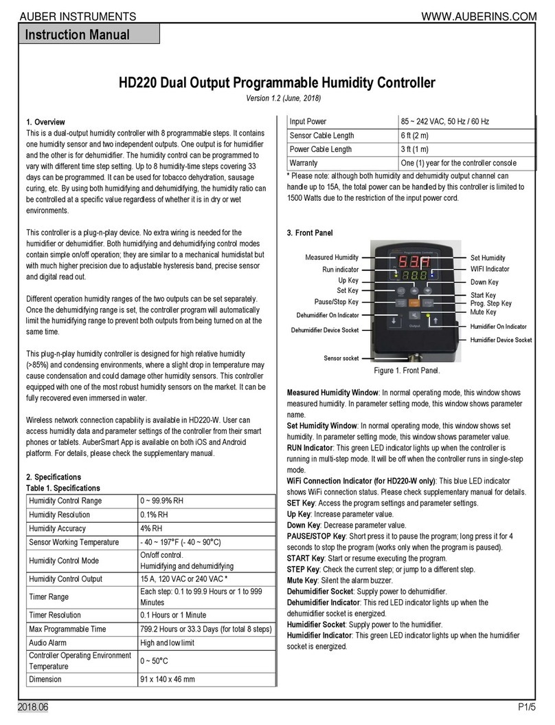
Auber Instruments HD220 User manual

Auber Instruments

Auber Instruments HD220 User manual

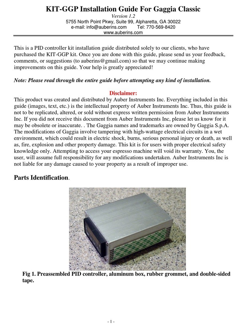
Auber Instruments Auberins KIT-GGP User manual

Auber Instruments

Auber Instruments Auberins KIT-GGP User manual

Auber Instruments EZboil DSPR310D User manual

Auber Instruments

Auber Instruments EZboil DSPR310D User manual

Auber Instruments EZboil DSPR310D User manual

Auber Instruments

Auber Instruments EZboil DSPR310D User manual

Auber Instruments KIT-CUBE2S User manual

Auber Instruments

Auber Instruments KIT-CUBE2S User manual

Auber Instruments SYL-3615 User manual

Auber Instruments

Auber Instruments SYL-3615 User manual

Auber Instruments WS-1500EPM Administrator Guide

Auber Instruments

Auber Instruments WS-1500EPM Administrator Guide

Auber Instruments EZboil DSPR120 User manual

Auber Instruments

Auber Instruments EZboil DSPR120 User manual

Auber Instruments SYL-53 2P Series User manual

Auber Instruments

Auber Instruments SYL-53 2P Series User manual

Auber Instruments KIT-RSPb User manual

Auber Instruments

Auber Instruments KIT-RSPb User manual

Auber Instruments EZboil DSPR320 User manual

Auber Instruments

Auber Instruments EZboil DSPR320 User manual

Auber Instruments SYL-3615 User manual

Auber Instruments

Auber Instruments SYL-3615 User manual

Auber Instruments AW-SYL-2352 User manual

Auber Instruments

Auber Instruments AW-SYL-2352 User manual

Auber Instruments SYL-2381-SSR User manual

Auber Instruments

Auber Instruments SYL-2381-SSR User manual

Auber Instruments EZboil DSPR310 User manual

Auber Instruments

Auber Instruments EZboil DSPR310 User manual

Auber Instruments Cube 5E User manual

Auber Instruments

Auber Instruments Cube 5E User manual

Auber Instruments DSPR300 User manual

Auber Instruments

Auber Instruments DSPR300 User manual

Auber Instruments DSPR400 User manual

Auber Instruments

Auber Instruments DSPR400 User manual

Auber Instruments WS-1500A Administrator Guide

Auber Instruments

Auber Instruments WS-1500A Administrator Guide

Auber Instruments SYL-2362B User manual

Auber Instruments

Auber Instruments SYL-2362B User manual

Auber Instruments AUB6500 User manual

Auber Instruments

Auber Instruments AUB6500 User manual

Popular Controllers manuals by other brands

ATEN PE4104AJ user manual

ATEN

ATEN PE4104AJ user manual

Allen-Bradley Micro800 installation instructions

Allen-Bradley

Allen-Bradley Micro800 installation instructions

ATTACK SQ-1 installation instructions

ATTACK

ATTACK SQ-1 installation instructions

Vacon 100X series marine installation guide

Vacon

Vacon 100X series marine installation guide

YOKOGAWA UT321 user manual

YOKOGAWA

YOKOGAWA UT321 user manual

TECSYSTEM NT935 instruction manual

TECSYSTEM

TECSYSTEM NT935 instruction manual

Baldor NextMove ES installation manual

Baldor

Baldor NextMove ES installation manual

BFT SP 3500 NSTALLATION AND USER'S MANUAL

BFT

BFT SP 3500 NSTALLATION AND USER'S MANUAL

Cascade TFC owner's manual

Cascade

Cascade TFC owner's manual

Salus EP310 installation manual

Salus

Salus EP310 installation manual

AUMA SQ 05.2 Operation instructions

AUMA

AUMA SQ 05.2 Operation instructions

Kohler APM303 user manual

Kohler

Kohler APM303 user manual

SGM TLD-612A user manual

SGM

SGM TLD-612A user manual

Vicon RS-232 instruction manual

Vicon

Vicon RS-232 instruction manual

MR TAPCON 250 Supplement

MR

MR TAPCON 250 Supplement

Reefe RPC22HM Operation Guide & Instruction Manual

Reefe

Reefe RPC22HM Operation Guide & Instruction Manual

Samson 3275 Mounting and operating instructions

Samson

Samson 3275 Mounting and operating instructions

Jetter JCM-501-E01 user manual

Jetter

Jetter JCM-501-E01 user manual

manuals.online logo
manuals.online logoBrands
  • About & Mission
  • Contact us
  • Privacy Policy
  • Terms and Conditions

Copyright 2025 Manuals.Online. All Rights Reserved.