manuals.online logo
Brands
  1. Home
  2. •
  3. Brands
  4. •
  5. Auber Instruments
  6. •
  7. Controllers
  8. •
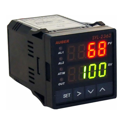
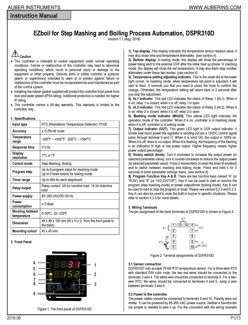
  9. Auber Instruments AW-SYL-2352 User manual

Auber Instruments AW-SYL-2352 User manual

AUBER INSTRUMENTS WWW.AUBERINS.COM
2022.10 P1/4
Supplementary User Guide for Wi-Fi Connectivity of AW-SYL-2352
Wi-Fi Module Firmware v1.0.7
Document version 1.0 (Oct 4th, 2022)
Caution
•This document is a supplementary user guide for the Wi-Fi enabled AW-
SYL-2352.
•This document only covers the Wi-Fi connectivity related topics. Please
refer to the user’s manual for the basic operations of the SYL-2352 PID
controllers.
•AW-SYL-2352 is installed with Auber’s 2nd generation Wi-Fi module, which
requires 2.4 GHz Wi-Fi networks and should be used with the AuberWifi
app.
1. Front Panel of AW-SYL-2352
Wi-Fi
Indicator
(blue)
Figure 1. The front panel of an AW-SYL-2352 controller.
The Wi-Fi status indicator is a blue LED indicator located on the top-right
corner of the display window.
2. Getting Started
2.1. How to Identify the Status of the Wi-Fi Module
The Wi-Fi Indicator. It is a blue LED indicator located on the top-right
corner of the display window. This indicator should light up after the
device is powered on.
Connection Status. There are three connection status of the Wi-Fi
module:
1) Pairing. The blue light blinks rapidly (about 4 times per second).
The Wi-Fi module is the pairing-mode, and it should generate a 2.4
GHz Wi-Fi band named as “AuberWifi_” and followed by 12
characters consisted of letters and numbers. This is the MAC
address of the Wi-Fi module.
2) Connecting. The blue light blinks slowly (about 1 time per second).
The Wi-Fi module is trying to connect to the Wi-Fi signal it is
instructed to connect to. This can happen right after a user tries to
add the device to the AuberWiFi app, and it can also happen when
the device has lost the Wi-Fi connection if the Wi-Fi signal is weak
or no long exists.
3) Connected. The blue light stays on solid. The Wi-Fi module is
connected to the Wi-Fi signal that it is instructed to connect to.
When you receive a new AW-SYL-2352 controller and power it up for the
first time, the blue indicator should blink rapidly. If the blue indicator is
not blinking rapidly, please see the next section for how to reset the Wi-
Fi module to paring mode.
2.2. How to Reset the Wi-Fi Module to Pairing Mode
Increase the current value of parameter COOL by “4” to reset the Wi-Fi
module to pairing mode. This action will only reset the Wi-Fi module and
it will NOT alter the existing value of the COOL parameter.
Here is a step-by-step instruction of how to do it on the device:
1) Press and hold the SET key for 2 seconds to bring up the
parameter menu.
2) Keep on short-pressing the SET key to scroll down the parameter
list till you see COOL on the top LED window. The value on the
bottom LED window is the current value of the COOL. By factory
default, this value should be 10. The dot in the lower-right corner
should be blinking rapidly.
3) Use the UP arrow key to increase the value by 4 and press the
SET key to confirm the change. In this example, increase the value
to “14” and press SET key to confirm and go to the next parameter.
4) You can press the A/M key and then press the SET key to exit the
menu. Or, you can keep on pressing the SET key till you exit the
menu. Or, don’t touch any key for 10 seconds to let the device
returns to the normal display mode automatically.
5) Now, the blue Wi-Fi status indicator should start blinking rapidly
and the Wi-Fi module should be in pairing mode. If you use check
the available Wi-Fi signals, you should see a signal called
“AuberWifi_xxxxxxxxxxxx”.
COOL
PV
1 0.
SV
OUT
A-M
AL2
AL1
WiFi
COOL
PV
1 4.
SV
OUT
A-M
AL2
AL1
WiFi SETSET
Figure 2. Reset the Wi-Fi module by increasing the COOL value by 4.
Instruction Manual
AUBER INSTRUMENTS WWW.AUBERINS.COM
2022.10 P2/4
3. Adding an AW-SYL-2352 to the AuberWiFi App
Important: The Wi-Fi module in AW-SYL-2352 can only connect to
a 2.4 GHz Wi-Fi network. Please make sure your router has a 2.4
GHz Wi-Fi network.
Important: The Wi-Fi name (SSID) and the password should have
no space (blank).
3.1. Download and Install the Latest AuberWifi App
Please download the AuberWifi app from the Android app store or the
iTune store and install it on your phone. Please grant the permission to
allow the app to access “File and media” and “Location” while using the
app.
3.2. Set the Device to Pairing Mode
Please see the section 2.2 for details.
3.3. Enable the Internet on Your Phone
Please make sure the internet connection on your phone is enabled. You
phone should be connected to the wireless router that you want to use
for connecting the AW-SYL-2352 controller. Please have the Wi-Fi
password ready. You’ll need to enter the password during the paring
process.
3.4. Add the Device to AuberWifi App
a) Please make sure your phone is connected to a 2.4 GHz Wi-Fi
signal from your wireless router. If you have a dual-band router with
both 2.4 GHz and 5 GHz Wi-Fi under the same name (SSID), you
don’t need to worry about which signal your phone is connecting to.
b) Open the AuberWifi App, tap on “add a device” button.
c) The Wi-Fi name (SSID) should have been filled to the first line.
Enter the Wi-Fi password and tap on the orange “Connect Device”
button.
Figure 3. Enter the password and tap the Connect Device button.
d) Please read the pop-up message boxes and tap “CONTINUE”.
Then, the app will take you to the “Internet” Configuration page on
your phone.
e) On the list of available Wi-Fi signals, select the one that starts with
“AuberWifi_”. This Wi-Fi signal is generated by the Wi-Fi module on
AW-SYL-2352 for pairing purpose. No password is needed.
Figure 4. The device will generate a signal with a SSID started with
“AuberWifi_”.
f) Once your phone is connected to the “AuberWifi_” Wi-Fi signal, it
will show that this Wi-Fi signal “can’t provide internet”.
•For users of Android phones,please wait for a pop-up message
from the notification bar on the top of the screen. The message will
remind you that the “AuberWifi_xxxxxxxxxxxx” has no internet
access and ask if you want to stay connected. Please select “Yes”
to stay connected. Otherwise, your phone will automatically switch
to another Wi-Fi signal that may have internet access, which will
cause the pairing process to fail.
Figure 5. For Android phone users, wait for the system notification, tap
on the notification box, and choose Yes to stay connected.
•For users of iPhones, you won’t see this notification unless you
wait for a much longer time. So, don’t worry about this pop-up
message.
Then, click the “Continue” button on the lower-right corner if you
are using an Android phone. Or, simply switch back to the
AuberWifi app if you are using an iPhone.
AUBER INSTRUMENTS WWW.AUBERINS.COM
2022.10 P3/4
Figure 6. For Android phone users, click the Continue button to go to the
next step. Or, simply switch back to the AuberWifi app.
g) In the AuberWifi app, the next pop-up message box will ask you to
confirm that your phone has connected to the “AuberWifi” network
generated by the device. Tap CONFIRM to go ahead with the
paring process.
h) Once you tap on the CONFIRM button, the SSID and password will
be sent to the Wi-Fi module on the device so that it can log on to
your wireless network.
i) If the pairing process is successful, the app will return to the app’s
main page and a new AW-SYL-2352 will appear on the list. The
blue Wi-Fi indicator will blink slowly for a few seconds and then turn
to solid. That means the device has been successfully connected
to your router.
j) If pairing is unsuccessful, the app will remain on the Add Device
page. The blue LED may turn to slow-blinking but will not turn to
solid. Please try again and make sure you check if the SSID
wireless signal is strong enough, if the password is correct, and
wait a little bit at step (g) until the “no internet access” notification
appears.
4. Accessing Devices from the AuberWifi App
4.1. App Main Page
On the AuberWifi app’s main page, you can see a list of devices that has
been added to the app, access the devices that are online, add a new
device, or access the general app menu.
Here is a screenshot of the app’s main page after we add the AW-SYL-
2352 to the AuberWifi app in Figure 7.
2. App Connection
Status
3. Device List
4. Add Device
1. Menu
Figure 7. The main page of AuberWifi app.
(1) Menu. This is a general app menu where you can check the app
version.
(2) App Connection Status Bar
This status bar ONLY shows the connection status between the app and
our cloud server. It does NOT show whether the device is connected to
your router or to the internet. When it shows “Connected”, it doesn’t
necessarily mean the device is connected to the internet. When it shows
“connecting…”, it doesn’t necessarily mean the device is offline.
Note: The app’s connection status can be affected by a few factors such
as the strength and the quality of the Wi-Fi signal that your phone is
receiving, the electro-magnetic noise in your environment that affect the
wireless connection of your phone, the other tasks or apps that are
running on your phone might affect your phone’s performance, and the
internet traffic between your internet provider to our server. You can try:
a) exit the app and re-open it; b) turn off the Wi-Fi connection on your
phone and try using the mobile data connection; 3) try a different Wi-Fi
network; 4) check if there is any other app could possibly block internet
traffic.
(3) Device List
Devices that have been added to the app will appear in the Device List
section. When the device is accessible from the app, the icon of the
device will appear in green and white. If the device is not accessible from
the app, the icon will appear in gray and white color. On this screen
shown in Figure 7, the device “A-2352-WiFi” is offline and the device
“2352-WiFi” is online.
AUBER INSTRUMENTS WWW.AUBERINS.COM
2022.10 P4/4
(4) Add a Device Button
To add a new device, tap this button and start the pairing process.
4.2. Device Main Page
A screenshot of the main page of AW-SYL-2352 is shown in Figure 8.
Main Panel
Data Plot
App Status
Device Name
Figure 8. The main page of device AW-SYL-2352.
Main Panel
The device’s main page is divided into 2 sections. The top half shows the
two display windows and the indicators in a similar way as they appear
on the device. The OUT indicator is shown as the Output status Bar.
The Set Value (SV) can only be viewed on this page. To change the SV,
please go to the “System Configuration” page by tapping the three-dot
menu button on the top-right corner.
Data Plot
The Wi-Fi module will record two sets of data in the past 50 minutes and
in the past 3 hours. Each data set has 100 data points, which contains a
time stamp, a probe value (PV), a set value (SV), and an output
percentage (OUT). A user can select from the dropdown list for “50 mins”
or “3 hours” to show the corresponding data plot. To export the data,
please go to the “Device” menu page and tap the “Export Data” button.
4.3. Device Menu
Bring up the menu by tapping the three-dot menu button on the top-right
corner. The menu has two items: “System Configuration” and “Device”.
System Configuration
Most of the parameters on AW-SYL-2352 can be access from the
“System Configuration” menu (see Figure 9(a)).
The first parameter is the Set Value (SV). The rest of the parameters are
listed in the same order as they are in the controller’s menu system. The
LOCK and EP1 to EP8 are not accessible from the app.
Device
In the Device menu page (see Figure 9(b)), a user can rename the
device, check the current firmware version of the Wi-Fi module, export
data, and go to our website to download the manual.
To export data, tap on the Export Data tab, the app will prompt you for
the next step. The data will be saved as a .CSV file and can be sent as
an attachment in an email.
The Wi-Fi communication module on AW-SYL-2352 is capable of over-
the-air (OTA) update for its own firmware. When a new firmware version
is published to the server, you can tap the “Version” tab to check for
firmware upgrade. If the firmware on this module is the latest, tapping on
this tab will do nothing.
(a)
(b)
Figure 9. (a) The System Configuration menu page. (b) The Device
menu page.
(End)
Auber Instruments Inc.
5755 North Point Parkway, Suite 99,
Alpharetta, GA 30022
www.auberins.com
Copyright © 2022 Auber Instruments Inc. All rights reserved.
No part of this datasheet shall be copied, reproduced, or transmitted in any way without
the prior, written consent of Auber Instruments. Auber Instruments retains the exclusive
rights to all information included in this document.

Other Auber Instruments Controllers manuals
Auber Instruments WS-1500EPM Administrator Guide

Auber Instruments

Auber Instruments WS-1500EPM Administrator Guide

Auber Instruments AUB6500 User manual

Auber Instruments

Auber Instruments AUB6500 User manual

Auber Instruments WS-1500A Administrator Guide

Auber Instruments

Auber Instruments WS-1500A Administrator Guide

Auber Instruments Cube 5E User manual

Auber Instruments

Auber Instruments Cube 5E User manual

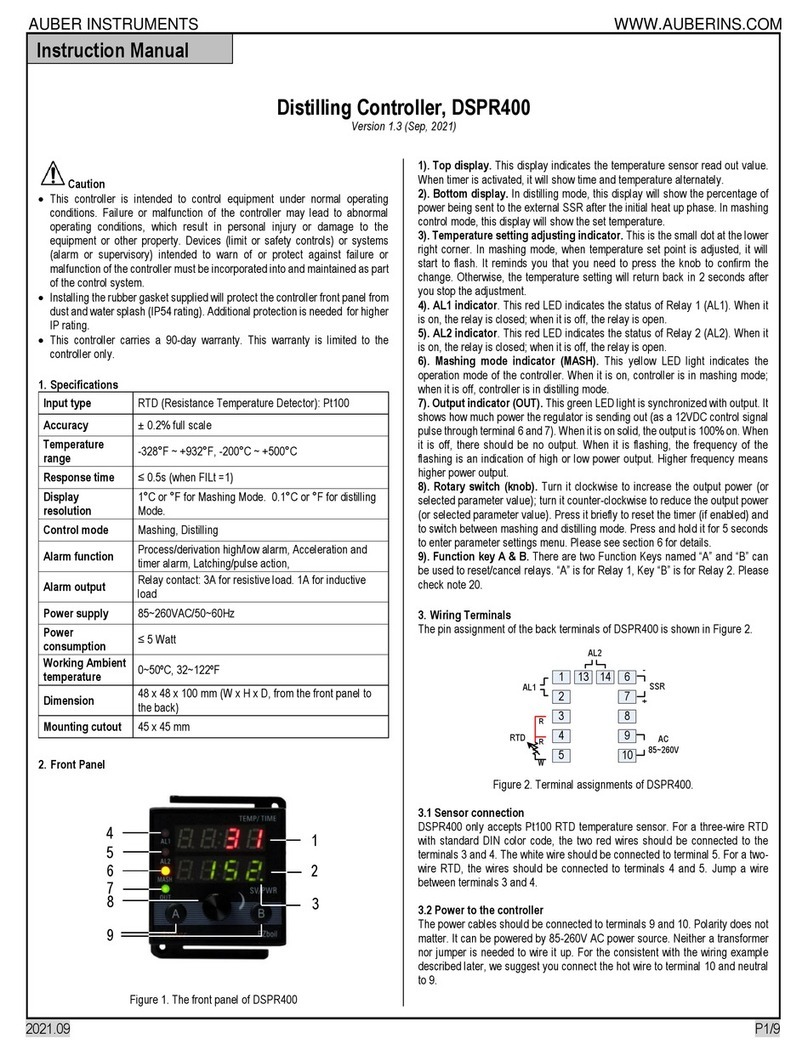
Auber Instruments EZboil DSPR310D User manual

Auber Instruments

Auber Instruments EZboil DSPR310D User manual

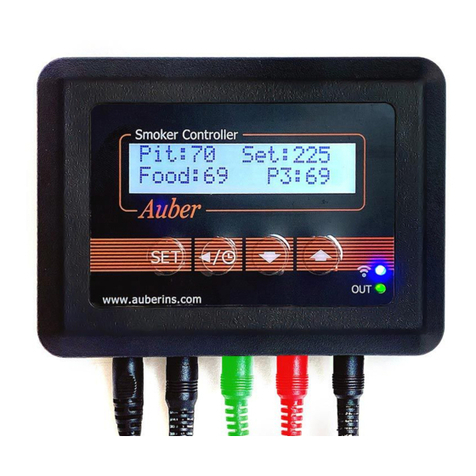
Auber Instruments DSPR400 User manual

Auber Instruments

Auber Instruments DSPR400 User manual

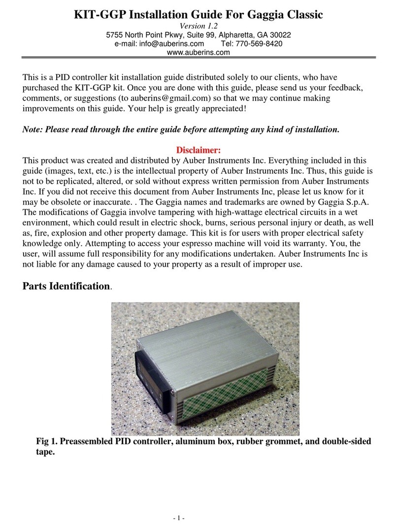
Auber Instruments KIT-Cube5E User manual

Auber Instruments

Auber Instruments KIT-Cube5E User manual

Auber Instruments SYL-2381-SSR User manual

Auber Instruments

Auber Instruments SYL-2381-SSR User manual

Auber Instruments HD220-W Instructions and recipes

Auber Instruments

Auber Instruments HD220-W Instructions and recipes

Auber Instruments SYL-3615 User manual

Auber Instruments

Auber Instruments SYL-3615 User manual

Auber Instruments HD220 User manual

Auber Instruments

Auber Instruments HD220 User manual

Auber Instruments EZboil DSPR120 User manual

Auber Instruments

Auber Instruments EZboil DSPR120 User manual

Auber Instruments EZboil DSPR320 User manual

Auber Instruments

Auber Instruments EZboil DSPR320 User manual

Auber Instruments SYL-2362B User manual

Auber Instruments

Auber Instruments SYL-2362B User manual

Auber Instruments EZboil DSPR310D User manual

Auber Instruments

Auber Instruments EZboil DSPR310D User manual

Auber Instruments Auberins KIT-GGP User manual

Auber Instruments

Auber Instruments Auberins KIT-GGP User manual

Auber Instruments HD330 User manual

Auber Instruments

Auber Instruments HD330 User manual
Auber Instruments RDK-300B User manual

Auber Instruments

Auber Instruments RDK-300B User manual

Auber Instruments SYL-3615 User manual

Auber Instruments

Auber Instruments SYL-3615 User manual

Auber Instruments SYL-2615 User manual

Auber Instruments

Auber Instruments SYL-2615 User manual

Auber Instruments SYL-53 2P Series User manual

Auber Instruments

Auber Instruments SYL-53 2P Series User manual

Auber Instruments DSPR300 User manual

Auber Instruments

Auber Instruments DSPR300 User manual

Auber Instruments EZboil DSPR310 User manual
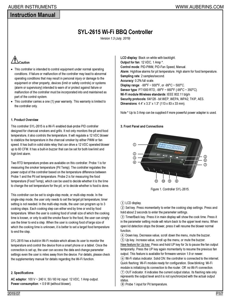
Auber Instruments

Auber Instruments EZboil DSPR310 User manual

Auber Instruments KIT-RSPb User manual
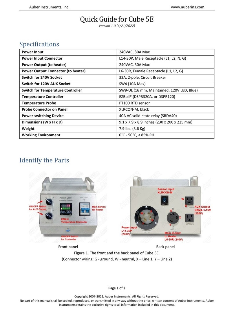
Auber Instruments

Auber Instruments KIT-RSPb User manual

Popular Controllers manuals by other brands
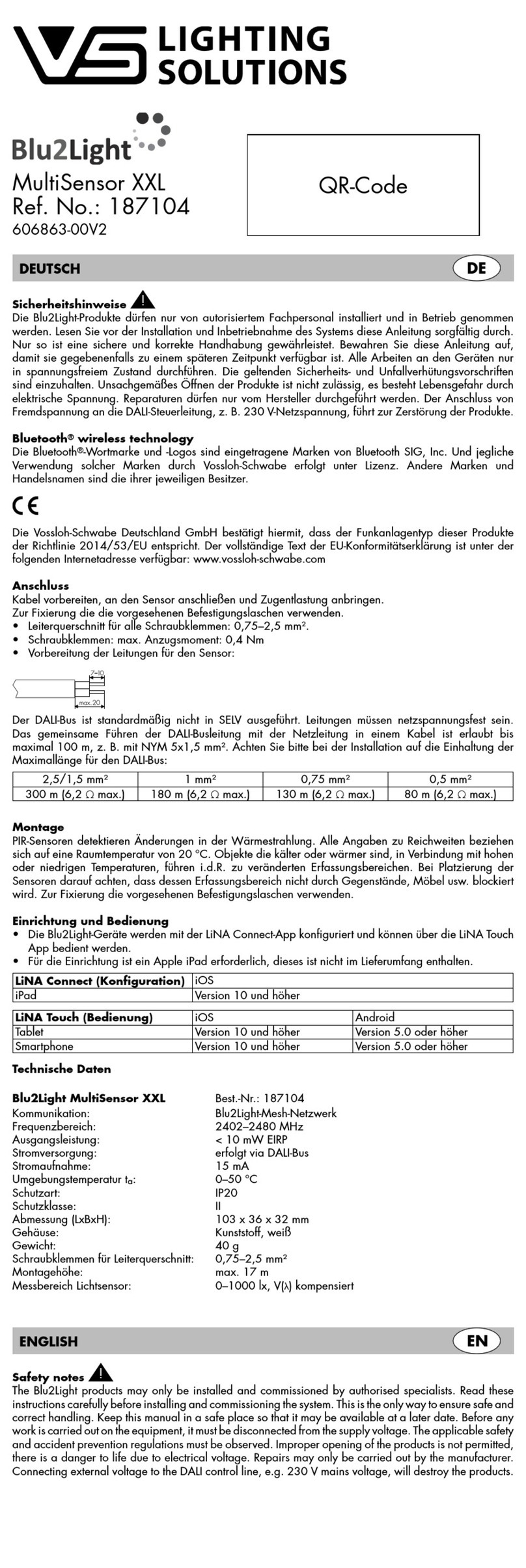
maxon motor EPOS2 24/2 Hardware reference

maxon motor

maxon motor EPOS2 24/2 Hardware reference

Newport FSM-CD300B user manual

Newport

Newport FSM-CD300B user manual

COMECO RT284U Operation manual

COMECO

COMECO RT284U Operation manual

Eurotech Helios Platform Hardware reference manual

Eurotech

Eurotech Helios Platform Hardware reference manual

TDS TSC 2000 series user manual

TDS

TDS TSC 2000 series user manual

SOMFY animeo IB + 1860085 installation guide

SOMFY

SOMFY animeo IB + 1860085 installation guide

Extron electronics MLC 206 Backlight Replacement Guide

Extron electronics

Extron electronics MLC 206 Backlight Replacement Guide

Emerson Bettis RGS Q-Series Installation, operation and maintenance manual

Emerson

Emerson Bettis RGS Q-Series Installation, operation and maintenance manual

SeaHawk LD1000 quick start guide

SeaHawk

SeaHawk LD1000 quick start guide

NI sbRIO-961 series quick reference

NI

NI sbRIO-961 series quick reference

Dometic Go Power! 30 AMP RVC MPPT user manual

Dometic

Dometic Go Power! 30 AMP RVC MPPT user manual

Samson 2357-31 Mounting and operating instructions

Samson

Samson 2357-31 Mounting and operating instructions

Parker 6K8 installation guide

Parker

Parker 6K8 installation guide

Lennox LXTFF01M manual

Lennox

Lennox LXTFF01M manual

Brama S-A1 user guide

Brama

Brama S-A1 user guide

HTW HTW-KJR86A1E Installation and operation manual

HTW

HTW HTW-KJR86A1E Installation and operation manual

ARCO LI-2B owner's manual

ARCO

ARCO LI-2B owner's manual

AMiO 01525 user manual

AMiO

AMiO 01525 user manual

manuals.online logo
manuals.online logoBrands
  • About & Mission
  • Contact us
  • Privacy Policy
  • Terms and Conditions

Copyright 2025 Manuals.Online. All Rights Reserved.