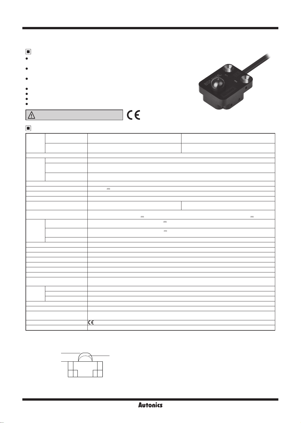
manuals.online logo
Brands
  1. Home
  2. •
  3. Brands
  4. •
  5. Autonics
  6. •
  7. Accessories
  8. •
  9. Autonics BS5-P Series User manual

Autonics BS5-P Series User manual

A-136
BS5-P Series
Features
Button operation enables accurate detection regardless of material, color, or
reflectance of target object
Optimized for transport detection of semiconductor wafer enclosures (FOUP,
FOSB, etc.)
Optical detection of button operation guarantees mechanical life cycle of 5 million
operations
Total of 4 red LED indicators (side:2, top:2) for higher visibility of operation status
Increased product durability with steel mounting brackets
Emitter OFF function and check stable operation functions
Built-in reverse polarity protection circuit and output short overcurrent protection circuit
Push Button Type Photomicro Sensors
Specifications
※1: Detection occurs when the button is pushed and the light source is blocked.
※2: Stop position: position of the button without any applied pressure
Output switching position: position where the output switches ON/OFF
Operation limit position: position of the button when fully pushed
※3: Pressure required to push the button from stop position to output switching position
※4: External input when using emitter OFF function or check stable operation functions.
※5: The weight includes packaging. The weight in parenthesis is for unit only.
※The temperature and humidity of environment resistance are rated at non-freezing or condensation.
Model
NPN open collector
output BS5-P1ML BS5-P1MD
PNP open collector
output BS5-P1ML-P BS5-P1MD-P
Operation method※1Push button type
Button
operation
※2
Stop position 5.0±0.4mm
Output switching
position 4.0±0.5mm
Operation limit position Below 0mm
Operation load※3Max. 3N (max. 0.3kgf)
Power supply 12-24VDC ±10% (ripple P-P: max. 10%)
Current consumption Max. 35mA
Light source Infrared LED (940nm)
Operation mode Light ON
(output OFF when button is pushed)
Dark ON
(output ON when button is pushed)
Control output NPN or PNP open collector output
·Load voltage: max. 26.4VDC ·Load current: max. 50mA ·Residual voltage: max. 1VDC
External
input※4
NPN output Emitter OFF: short at 0V or max. 0.25VDC (outow current max. 30mA)
Emitter ON: open (leakage current max. 0.4mA)
PNP output Emitter OFF: short at +V or min. -0.25VDC of +V (absorption current max. 30mA)
Emitter ON: open (leakage current max. 0.4mA)
Response Under 1ms
Protection circuit Reverse polarity protection circuit, output short overcurrent protection circuit
Indicator Operation indicator: red LED
Insulation resistance Over 20MΩ (at 250VDC megger)
Noise immunity ±240V of square wave noise (pulse width:1 ㎲) from the noise simulator
Dielectric strength 1,000VAC at 50/60Hz for 1min
Vibration 1.5mm amplitude at 10 to 55Hz frequency in each X, Y, Z direction for 2 hours
Shock 500m/s² (approx. 50G) in each X, Y, Z direction for 3 times
Mechanical life cycle Min. 5,000,000 operations
(1 operation = stop position - operation limit position - stop position)
Environ-
ment
Ambient illuminance Fluorescent lamp: max. 1,000lx (receiver illuminance)
Ambient temperature -20 to 55℃, storage: -25 to 70℃
Ambient humidity 35 to 85%RH, storage: 35 to 85%RH
Protection structure IP40 (IEC standard)
Material Case: polycarbonate + glass ber, button: polyoxymethylene, sleeve: SUS304 (steel use stainless 304)
Cable Ø3mm, 4-wire, 1m
(AWG 28, core diameter: 0.08mm, no. of core wires: 19, insulator diameter: Ø0.88mm)
Approval
Weight※5Approx. 50g (approx. 30g)
Stop position
Operation limit
position
Output switching position: 4.0±0.5mm
Please read “Safety Considerations”
in the instruction manual before using.
A-137
Push Button Type Photomicro Sensors
SENSORS
CONTROLLERS
MOTION DEVICES
SOFTWARE
(A)
Photoelectric
Sensors
(B)
Fiber Optic
Sensors
(C)
LiDAR
(D)
Door/Area
Sensors
(E)
Vision
Sensors
(F)
Proximity
Sensors
(G)
Pressure
Sensors
(H)
Rotary
Encoders
(I)
Connectors/
Connector Cables/
Sensor Distribution
Boxes/ Sockets
※
If short-circuit the control output terminal or supply current over the rated specication, normal control signal is not output due to the output
short over current protection circuit.
Operation Mode
Connections
Control Output Diagram
Photoelectric sensor circuit
Connection
Main circuit
Max. 50mA
External
input
12-24VDC
+
-
(black)output
(white)control
(blue)0V
(brown)+V
Output short
overcurrent
protection
circuit
Load
Photoelectric sensor circuit
Connection
External
input
(black)output
(white)control
(blue)0V
(brown)+V
Max. 50mA 12-24VDC
Main circuit
+
-
Output short
overcurrent
protection
circuit
Load
NPN open collector output PNP open collector output
Operation mode Light ON(output OFF when button is pushed) Dark ON(output ON when button is pushed)
Button
position
Pushed
Raised Pushed
Raised
Receiver
operaion
Received light
Interrupted light
Received light
Interrupted light
Operation indicator
(redLED)
ON
OFF ON
OFF
Transistor
output
ON
OFF
ON
OFF
Load
(white)Control
(white)Control
(brown)+V
(brown)+V
(blue)0V
(blue)0V
12-24VDC
(black)Output
(black)Output
External input
External input
+
-
12-24VDC
Load
+
-
NPN open collector output
PNP open collector output
A-138
BS5-P Series
Dimensions
Installation
(unit: mm)
Operation indicator (red)
2-Ø3.2
4-R3
6.5
21.3
25
3.7
20
13
Operation indicator (red)
Ø3, 1m
Ø8
9 5.1
4
3
6-R3
18
3
When installing the product, tighten the screw with a tightening torque of 0.59N·m.
Do not pull the cable with a tensile strength of 30N or over. It may result in fire due to the broken wire.
1) Installation on non-flush surface
Install the sensor after fitting the sensor in the opening as shown in the figure below.
2) Installation on flush surface
Insert a spacer between the installation surface and the mounting surface of the sensor as shown in the figure below.
※Recommended size
D: 6mm
d: 3.3mm
L: 4±0.1mm
D
d
L
Installation surface
Installation
surface
Spacer
A-139
Push Button Type Photomicro Sensors
SENSORS
CONTROLLERS
MOTION DEVICES
SOFTWARE
(A)
Photoelectric
Sensors
(B)
Fiber Optic
Sensors
(C)
LiDAR
(D)
Door/Area
Sensors
(E)
Vision
Sensors
(F)
Proximity
Sensors
(G)
Pressure
Sensors
(H)
Rotary
Encoders
(I)
Connectors/
Connector Cables/
Sensor Distribution
Boxes/ Sockets
Functions
Emitter OFF function
The emitter LED can be turned ON/OFF without pushing the button, to test for stable operation of the receiver.
※When using the emitter OFF function and check stable operation function simultaneously, the transistor used should be able to open
and close 50mA/10V and resistance should be over 1/8W. Failure may cause product damage.
※When emitter OFF function and stable operation check function is not used, insulate the control (white) wire.
Otherwise, it may result in product damage.
Check stable operation function
Reduces the LED intensity by approximately 20% while button is not pushed, and check that the receiver is still receiving light
(same transistor ON status as at 100%) This ensures that sensor will not malfunction due to changing light intensity.
Simultaneous use of emitter OFF and check stable operation function
Follow the circuit diagram below:
NPN open collector output PNP open collector output
Sensor
External
connection
(brown)+V
(black)Output
(white)Control
(blue)0V
Emitter
OFF
function
Sensor
External
connection
(brown)+V
(black)Output
(white)Control
(blue)0V
Emitter
OFF
function
NPN open collector output PNP open collector output
Sensor External
connection
(brown)+V
(black)Output
(white)Control
(blue)0V
390Ω
Check
stable
operaion
Sensor External
connection
(brown)+V
(black)Output
(white)Control
(blue)0V
390Ω
Check
stable
operaion
NPN open collector output PNP open collector output
Sensor
External
connection
(brown)+V
(black)Output
(white)Control
(blue)0V
390Ω
Emitter
OFF
function
Check
stable
operaion
Sensor
External
connection
(brown)+V
(black)Output
(white)Control
(blue)0V
Emitter
OFF
function
Check
stable
operaion
390Ω

This manual suits for next models

4

Other Autonics Accessories manuals

Autonics PSAN Series User manual

Autonics

Autonics PSAN Series User manual

Autonics BPS Series User manual

Autonics

Autonics BPS Series User manual

Autonics PFI Series User manual

Autonics

Autonics PFI Series User manual

Autonics VG-C04 -25E Series User manual

Autonics

Autonics VG-C04 -25E Series User manual

Autonics BX Series User manual

Autonics

Autonics BX Series User manual

Autonics BR Series User manual

Autonics

Autonics BR Series User manual

Autonics ADS-A Series User manual

Autonics

Autonics ADS-A Series User manual

Autonics PRD Series User manual

Autonics

Autonics PRD Series User manual

Autonics BA Series User manual

Autonics

Autonics BA Series User manual

Autonics BEN Series User manual

Autonics

Autonics BEN Series User manual

Autonics PSN Series User manual

Autonics

Autonics PSN Series User manual

Autonics BC Series User manual

Autonics

Autonics BC Series User manual

Autonics BW Series User manual

Autonics

Autonics BW Series User manual

Autonics BM Series User manual

Autonics

Autonics BM Series User manual

Autonics BS5 Series User manual

Autonics

Autonics BS5 Series User manual

Autonics PSAN Series User manual

Autonics

Autonics PSAN Series User manual

Autonics BWM Series User manual

Autonics

Autonics BWM Series User manual

Autonics ADS-SE1 Series User manual

Autonics

Autonics ADS-SE1 Series User manual

Autonics BA Series User manual

Autonics

Autonics BA Series User manual

Autonics BRQ Series User manual

Autonics

Autonics BRQ Series User manual

Autonics BD Series User manual

Autonics

Autonics BD Series User manual

Autonics CR Series User manual

Autonics

Autonics CR Series User manual

Autonics BWM Series User manual

Autonics

Autonics BWM Series User manual

Autonics BUM Series User manual

Autonics

Autonics BUM Series User manual

Popular Accessories manuals by other brands

Alice's Garden OMBREC manual

Alice's Garden

Alice's Garden OMBREC manual

Advaning CLASSIC Series owner's manual

Advaning

Advaning CLASSIC Series owner's manual

HoMedics Aroma ARMH-340 instruction manual

HoMedics

HoMedics Aroma ARMH-340 instruction manual

Tascam US-2000 owner's manual

Tascam

Tascam US-2000 owner's manual

EnergyLux ES-M09B manual

EnergyLux

EnergyLux ES-M09B manual

Waterpik WF-07 user manual

Waterpik

Waterpik WF-07 user manual

X-pole Xpert instruction manual

X-pole

X-pole Xpert instruction manual

Honeywell P7640U installation instructions

Honeywell

Honeywell P7640U installation instructions

Homemanageables HM-FS001 manual

Homemanageables

Homemanageables HM-FS001 manual

Tronic TPB 10000 A1 Operation and safety notes

Tronic

Tronic TPB 10000 A1 Operation and safety notes

FONRI NAS-PD02W0 user guide

FONRI

FONRI NAS-PD02W0 user guide

Leuze SET-AC manual

Leuze

Leuze SET-AC manual

ATI Technologies SR-61 manual

ATI Technologies

ATI Technologies SR-61 manual

Samsung S Pen Pro quick start guide

Samsung

Samsung S Pen Pro quick start guide

Vertiv SmartRow DCR Installer/user guide

Vertiv

Vertiv SmartRow DCR Installer/user guide

Tecfluid FLOMID Series instruction manual

Tecfluid

Tecfluid FLOMID Series instruction manual

Kopp Radio motion sensor instruction manual

Kopp

Kopp Radio motion sensor instruction manual

GRASS VALLEY 8964FS - datasheet

GRASS VALLEY

GRASS VALLEY 8964FS - datasheet

manuals.online logo
manuals.online logoBrands
  • About & Mission
  • Contact us
  • Privacy Policy
  • Terms and Conditions

Copyright 2025 Manuals.Online. All Rights Reserved.