Model
NPN output
BA2M-DDT BA2M-DDTD
PNP output
BA2M-DDT-P BA2M-DDTD-P
Sensing type
Diffuse Reective
Sensing distance
2m (non-glossy white paper 200×200mm)
Sensing target
Translucent, opaque materials
Hysteresis
Max. 20% at sensing distance
Response time
Max. 1ms
Power supply
12-24VDCᜡ±10% (ripple P-P: max. 10%)
Current
consumption
Max. 15mA (max. 30mA when the output is ON)
Light source
Infrared LED (850nm)
Sensitivity
adjustment
Sensitivity adjuster
Operation mode
Light ON Dark ON
Control output
NPN or PNP open collector output
●Load voltage: max.26.4VDCᜡ ●Load current: max.100mA
●
Residual voltage -NPN: max.1VDCᜡ, PNP: max. 2.5VDC
Protection
circuit
Reverse polarity protection circuit,
output short overcurrent protection circuit
Receiver
Photo IC
Indicator
Operation: red, stability: orange (Light On), green (Dark On)
Insulation
resistance
Over 20MΩ (at 500VDC megger)
Noise immunity
±240V the square wave noise (pulse width:1㎲)
by the noise simulator
Dielectric
strength
1,000VAC 50/60Hz for 1minute
Vibration
resistance
1.5mm amplitude at frequency of 10 to 55Hz
in each of X, Y, Z directions for 2 hours
Shock
resistance
100m/s² in X, Y, Z directions for 3 times
Environment
Ambient
illumination
Sunlight: max.11,000lx,
incandescent lamp: max.3,000lx (receiver illumination)
Ambient
temperature
-25 to 55℃, storage: -25 to 70℃
Ambient
humidity
35 to 85%RH, storage: 35 to 85%RH
Protection
IP64 (IEC standards)
Material
Case: ABS, Sensing part: PC, Indicator: PC, VR: IXEF
Cable
ø3mm, 3-wire, Length: 2m(AWG24, Core diameter: 0.08mm,
Number of cores: 40, Insulator diameter: ø1mm)
Accessory
Adjuster screwdriver
Approval
Weight Approx. 50g
(unit: mm)
Please check wiring after setting the target and supply the power to this sensor.
When using photoelectric sensors closely over two units, it may result in malfunction
due to mutual interference.
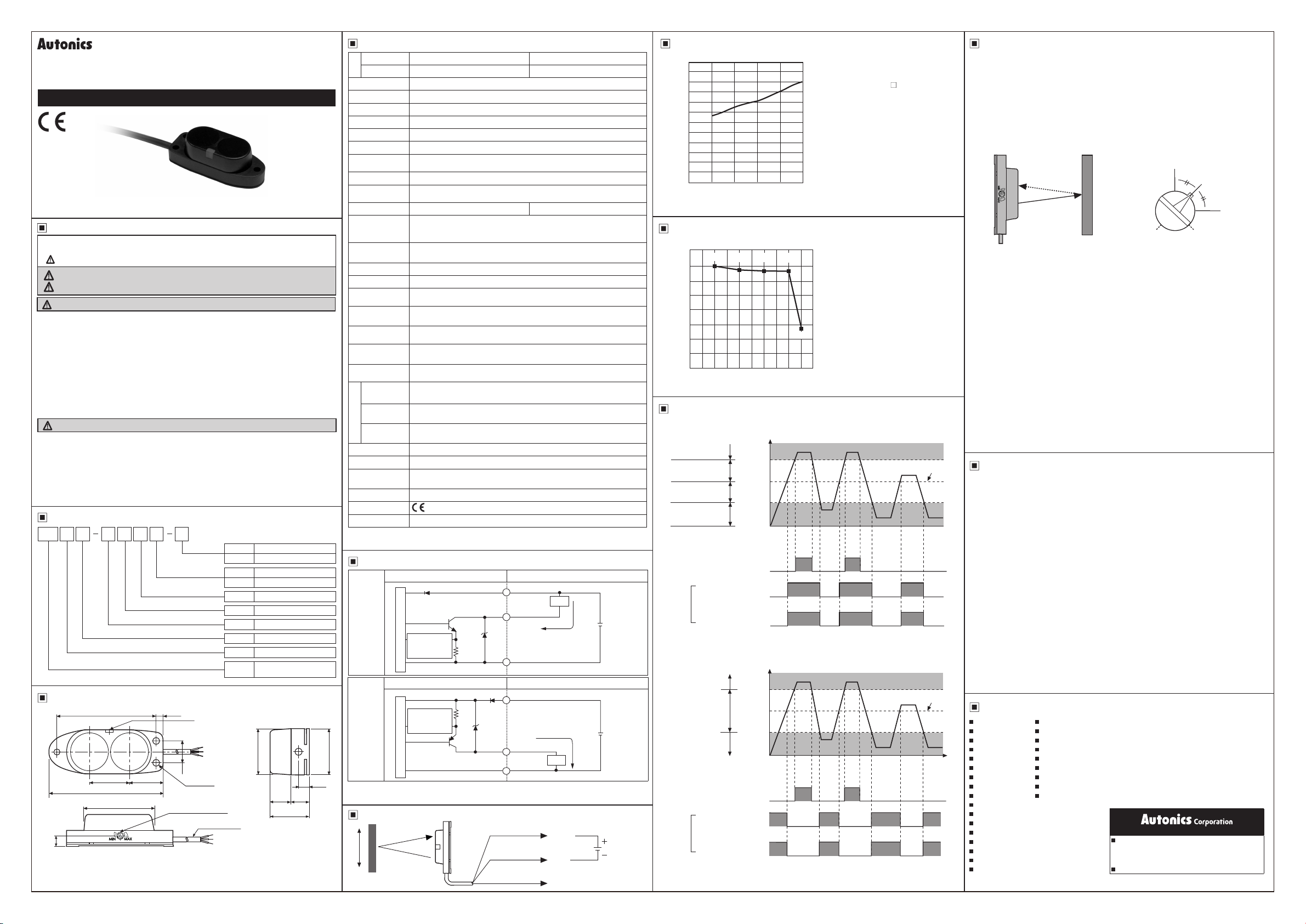
When installing the product, tighten the screw with a tightening torque of 0.5N.m.
Mount this unit at center position where operation LED turns on as moving the unit
toward right or left, up or down
41.5 3.5
16 16
48.5
34.5
10
18.5
19
4.7
2color LED
(operation.stability indicator)
M3 Bolt
Sensitivity adjuster
ø3, Cable:2m
87.5
15.5
2.3
Safety Considerations
Warning
Caution
Ordering Information
Dimensions
Item
Sensing distance
Sensing distance unit
Sensing type
Control
output
Power supply
Output
NPN open collector output
P
PNP open collector output
Light ON
DDark ON
TTransistor output
DDC power
DDiffuse Reective
MUnit: m
Number
Sensing distance
BA Photoelectric sensor
series
Operation mode
Detecting distance(m)
Detecting target size(mm)
50 80 100 150 200
2.2
2.0
1.8
1.6
1.4
1.2
1.0
0.8
0.6
0.4
0.2
0
※ It shows the change of detecting
distance by size of targets.
Standard targets: 200×200mm
non-glossy white paper.
※ It shows the rate of detecting
distance by color of targets.
Non-glossy white paper 100%
White Yellow Red Blue
Black
(%)
100
90
75
60
45
30
15
0
● Light ON
● Dark ON
● Optical axis adjustment
1. When sensing the object, set the sensitivity adjustment in stable Light ON area (orange:
Light On, green: Dark On) as shown 'operation mode chart'.
2. The sensitivity should be adjusted depending on a sensing target or mounting place.
3. Set the target at a position to be detected by the beam, then turn the adjuster until position
ⓐ where the indicator turns on from min. position of the adjuster.
4. Take the target out of the sensing area, then turn the adjuster until position ⓑwhere the
indicator turns on. If the indicator dose not turn on, Max. position ⓑ.
5. Set the adjuster at the center of two switching position ⓐ, ⓑ.
※
The sensing distance indicated on specication chart is for 200 X 200mm of non-glossy
white paper. Be sure that it can be different by size, surface and gloss of target.
● Adjustment
Sensing
target
Optimal
position
MIN
ⓐ
MAX
ⓑ
Sensing target
(brown)
(blue)
(black)Output
12-24VDC
Light ON
operation
Stable light ON
level
Unstable light ON
level
Unstable light OFF
level
Stable light OFF
level
Operating
level
(Control output according to amount of receiving light)
high
low
ON
OFF
ON
OFF
ON
OFF
Stability indicator
(Orange LED)
Operation
indicator
(Red LED)
Transistor
output
Incident
light
level
Unstable operation
level
(Control output according to amount of receiving light)
Stable light ON
level
Stable light OFF
level
Dark ON
operation
high
low
ON
OFF
ON
OFF
ON
OFF
Stability indicator
(Orange LED)
Operation
indicator
(Red LED)
Incident
light
level
Operating
level
BA 2 DM T PD D
PNP
open
collector
output
Photoelectric sensor circuit Connection
Output short
overcurrent
protection circuit
Main circuit
(blue)0V
(black)Output
(brown)+V
Max. 100mA
12-24VDC
+
-
Load
※The temperature or humidity mentioned in Environment indicates a non freezing or condensation
environment.
Transistor
output
Photoelectric Sensors Temperature Controllers
Fiber Optic Sensors Temperature/Humidity Transducers
Door Sensors SSRs/Power Controllers
Door Side Sensors Counters
Area Sensors Timers
Proximity Sensors Panel Meters
Pressure Sensors Tachometers/Pulse(Rate)Meters
Rotary Encoders Display Units
Connectors/Sockets Sensor Controllers
Switching Mode Power Supplies
Control Switches/Lamps/Buzzers
I/O Terminal Blocks & Cables
Stepper Motors/Drivers/Motion Controllers
Graphic/Logic Panels
Field Network Devices
Laser Marking System(Fiber, CO₂, Nd:YAG)
Laser Welding/Cutting System
1. Fail-safe device must be installed when using the unit with machinery that may
cause serious injury or substantial economic loss. (e.g. nuclear power control,
medical equipment, ships, vehicles, railways, aircraft, combustion apparatus,
safety equipment, crime/disaster prevention devices, etc.)
Failure to follow this instruction may result in re, personal injury, or economic loss.
2. Do not disassemble or modify the unit.
Failure to follow this instruction may result in re.
3. Do not connect, repair, or inspect the unit while connected to a power source.
Failure to follow this instruction may result in re.
4. Check ‘Connections’ before wiring.
Failure to follow this instruction may result in re.
1. Use the unit within the rated specications.
Failure to follow this instruction may result in re or product damage.
2. Use dry cloth to clean the unit, and do not use water or organic solvent.
Failure to follow this instruction may result in re.
3. Do not use the unit in the place where ammable/explosive/corrosive gas,
humidity, direct sunlight, radiant heat, vibration, impact, or salinity may be present.
Failure to follow this instruction may result in re or explosion.
※Please observe all safety considerations for safe and proper product operation to avoid
hazards.
※
symbol represents caution due to special circumstances in which hazards may occur.
Warning Failure to follow these instructions may result in serious injury or death.
Caution
Failure to follow these instructions may result in personal injury or product damage.
※
The above specifications are subject to change and some models may be
discontinued without notice.
※
Be sure to follow cautions written in the instruction manual and the technical
descriptions (catalog, homepage).
NPN
open
collector
output
Photoelectric sensor circuit Connection
Main circuit
(blue)0V
Max. 100mA
12-24VDC
+
-
(black)Output
(brown)+V
Load
Output short
overcurrent
protection circuit
http://www.autonics.com
HEADQUARTERS:
18, Bansong-ro 513beon-gil, Haeundae-gu, Busan,
South Korea, 48002
TEL: 82-51-519-3232
DRW171447AA
Photoelectric Sensor
BA SERIES
Specication
Control Output Circuit Diagram
Connection
Mounting and Adjustment
Cautions during Use
Detecting Distance against the Target Size
Detecting Distance against the Target Color
Operation Mode
Major Products
Thank you for choosing our Autonics product.
Please read the following safety considerations before use.
I N S T R U C T I O N M A N U A L
DRW171447AA
※
If short-circuit the control output terminal or supply current over the rated specication,
normal control signal is not output due to the output short over current protection circuit.
1. Follow instructions in 'Cautions during Use'. Otherwise, it may cause unexpected
accidents.
2. When connecting a DC relay or other inductive load to the output, remove surge by
using diodes or varistors.
3. Use the product, 0.5 sec after supplying power.
When using separate power supply for the sensor and load, supply power to sensor
first.
4. 12-24VDC power supply should be insulated and limited voltage/current or Class 2,
SELV power supply device.
5. Wire as short as possible and keep away from high voltage lines or power lines, to
prevent inductive noise.
6. When using switching mode power supply to supply the power, ground F.G. terminal
and connect a condenser between 0V and F.G. terminal to remove noise.
7. When using sensor with the equipment which generates noise (switching regulator,
inverter, servo motor, etc.), ground F.G. terminal of the equipment.
8. This unit may be used in the following environments.
①Indoors (in the environment condition rated in 'Specifications')
②Altitude max. 2,000m
③Pollution degree 3
④Installation category II


