I-31
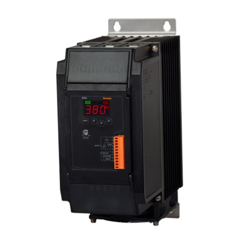
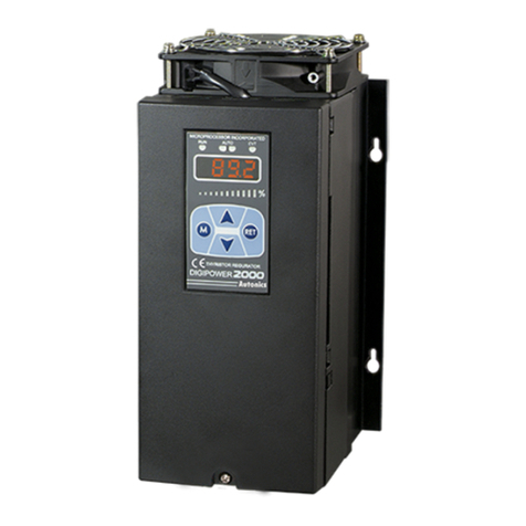
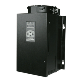
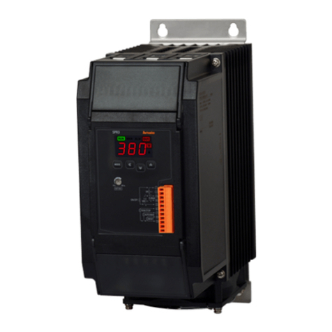
LED Display, Single-Phase, Slim, Power Controller
(A)
Photoelectric
Sensors
(B)
Fiber
Optic
Sensors
(C)
Door/Area
Sensors
(D)
Proximity
Sensors
(E)
Pressure
Sensors
(F)
Rotary
Encoders
(G)
Connectors/
Connector Cables/
Sensor Distribution
Boxes/Sockets
(H)
Temperature
Controllers
(I)
SSRs / Power
Controllers
(J)
Counters
(K)
Timers
(L)
Panel
Meters
(M)
Tacho /
Speed / Pulse
Meters
(N)
Display
Units
(O)
Sensor
Controllers
(P)
Switching
Mode Power
Supplies
(Q)
Stepper Motors
& Drivers
& Controllers
(R)
Graphic/
Logic
Panels
(S)
Field
Network
Devices
(T)
Software
Specications
Model SPR1-1 SPR1-2 SPR1-3 SPR1-4
Control phase Single-phase
Rated load voltage
(50/60Hz) 110VACᜠ220VACᜠ380VACᜠ440VACᜠ
Power supply 100-240VACᜠ 50/60Hz
Min. load current 1A
Permissible voltage range 90 to 110% of rated voltage
Power consumption Rated load current 25A/35A/50A: max. 7VA
Rated load current 70A/100A/150A: max. 12VA
Display method 3-digit 7-segment LED
Indicator Operation indicator/Manual control indicator: green LED
Alarm indicator/output indicator/unit (V, A) indicator: red LED
Control method
Phase control: normal control mode, constant current/constant voltage/constant power feedback control mode
Cycle control: xed cycle control mode, variable cycle control mode
ON/OFF control
Applied load Phase control, ON/OFF control: resistance load, inductive load
Cycle control: resistance load
Control input Auto control: DC4-20mA, 1-5VDCᜡ, ON/OFF contact (no-voltage input), pulse voltage (5-12VDCᜡ)
Manual control: outside adjuster (10kΩ), inside adjuster (output limit)
Digital input (DI) RUN/STOP switching, AUTO/MAN switching, RESET
Output Alarm 250VACᜠ 3A, 30VDCᜡ 3A, 1c resistive load
Communication RS485 communication output (Modbus RTU method), max. connection: 31 units
Output range
Phase control: 0 to 98%
Cycle control: 0 to 100%
ON/OFF control: 0%, 100%
Output accuracy
Normal control: within ±10% F.S. of rated load voltage
Constant current feedback control: within ±3% F.S. of rated load current
Constant voltage feedback control: within ±3% F.S. of rated load voltage
Constant power feedback control: within ±3% F.S. of rated load power
Set method By front keys, by communication
Functions
Output limit (OUT ADJ), AUTO/MAN selection, control method selection, RESET, SOFT START, SOFT UP/DOWN,
output high/low limit, input correction, input slope correction, monitoring (control input, load voltage/current/power/
resistance, power supply frequency, heatsink temperature)
Alarm Overcurrent alarm, overvoltage alarm, fuse break alarm, SCR error alarm, heater break alarm, heatsink
overheat alarm
Cooling method Rated load current 25A/35A/50A: natural cooling
Rated load current 70A/100A/150A: forced air cooling (with the cooling fan)
Insulation resistance Over 200MΩ (at 500VDC megger)
Dielectric strength 2,000VAC 50/60Hz for 1 min (between input terminals and power terminals)
Output leakage current Max. 10mArms
Noise immunity ±2kV the square wave noise (pulse width: 1㎲) by the noise simulator
Memory retention Approx. 10 years (when using non-volatile semiconductor memory type)
Vibration Mechanical 0.75mm amplitude at frequency of 5 to 55Hz in each X, Y, Z direction for 2 hours
Malfunction 0.5mm amplitude at frequency of 5 to 55Hz in each X, Y, Z direction for 10 min
Environ
ment
Ambient temp. -10 to 55℃, storage: -20 to 80℃
Ambient humi. 35 to 85%RH, storage: 35 to 85%RH
Accessory 11-pin connector
Approval ᜢ
Weight※1
Rated load current 25A/35A/50A: approx. 1.6kg (approx. 1.3kg)
Rated load current 70A: approx. 1.65kg (approx. 1.35kg)
Rated load current 100A/150A: approx. 3.2kg (approx. 2.8kg)
※1: The weight includes packaging. The weight in parenthesis is for unit only.
※Environment resistance is rated at no freezing or condensation.
