Avdel 7556 User manual

I n s t r u c t i o n M a n u a l
Threaded Insert Power Tool
Pass onto user to read and keep for reference
07556
07556

AIR PRESSURE Minimum - Maximum 5 - 8 bar 75 - 120 lbf/in2
FREE AIR VOLUME REQUIRED @ 5 bar / 75 lbf/in2510 litres/min 18 ft3 /min
MOTOR SPEED @ 75 lb/in21000 RPM (clockwise)
CYCLE TIME Approximately 3 seconds
NOISE LEVEL 80 dB(A)
WEIGHT Without nose equipment 1.76 kg 3.9 lb
VIBRATION Less than 2.5 m/s28 ft/s2
S P E C I F I C A T I O N S F O R 0 7 5 5 6 T O O L
AVDEL policy is one of continuous development. Specifications shown in this document may be subject to changes which
may be introduced after publication. For the latest information always consult Avdel.
■
■
■
■
■
■
■
■
■
■
■
■
■
■
■
■
■
■
■
■
■

CO N T E N T S
General 2
Specific to 07556 Tool 3
General 4
Tool Dimensions / Selection 4-5
Air Supply 6
Operating Procedure 6
Clutch Adjustment - Accessories 7
Fitting/Servicing/Components 8-9
Regular Servicing 10
Maintenance 11-13
General Assembly & Parts List 14-15
Fault Diagnosis Table 16
S A F E T Y
I N T E N T O F U S E
P U T T I N G I N T O S E R V I C E
N O S E A S S E M B L I E S
S E R V I C I N G
F A U L T D I A G N O S I S
1

SA F E T Y
This instruction manual must be read with particular attention to the following safety rules,
by any person installing, operating or servicing this tool.
DO NOT USE OUTSIDE THE DESIGN INTENT.
DO NOT USE EQUIPMENT WITH THIS TOOL/MACHINE OTHER THAN THAT
RECOMMENDED AND SUPPLIED BY AVDEL.
ANY MODIFICATION UNDERTAKEN BY THE CUSTOMER TO THE TOOL/MACHINE,
NOSE ASSEMBLIES, ACCESSORIES OR ANY EQUIPMENT SUPPLIED BY AVDEL OR THEIR
REPRESENTATIVES, SHALL BE THE CUSTOMER'S ENTIRE RESPONSIBILITY. AVDEL WILL BE
PLEASED TO ADVISE UPON ANY PROPOSED MODIFICATION.
THE TOOL/MACHINE MUST BE MAINTAINED IN A SAFE WORKING CONDITION AT
ALL TIMES AND EXAMINED AT REGULAR INTERVALS FOR DAMAGE AND FUNCTION BY
TRAINED COMPETENT PERSONNEL. ANY DISMANTLING PROCEDURE SHALL BE
UNDERTAKEN ONLY BY PERSONNEL TRAINED IN AVDEL PROCEDURES. DO NOT DISMANTLE
THIS TOOL/MACHINE WITHOUT PRIOR REFERENCE TO THE MAINTENANCE INSTRUCTIONS.
CONTACT AVDEL WITH YOUR TRAINING REQUIREMENTS.
THE TOOL/MACHINE SHALL AT ALL TIMES BE OPERATED IN ACCORDANCE WITH
RELEVANT HEALTH AND SAFETY LEGISLATION. IN THE U.K. THE “HEALTH AND SAFETY AT
WORK ETC. ACT 1974” APPLIES. ANY QUESTION REGARDING THE CORRECT OPERATION
OF THE TOOL/MACHINE AND OPERATOR SAFETY SHOULD BE DIRECTED TO AVDEL.
THE PRECAUTIONS TO BE OBSERVED WHEN USING THIS TOOL/MACHINE MUST BE
EXPLAINED BY THE CUSTOMER TO ALL OPERATORS.
ALWAYS DISCONNECT THE AIRLINE FROM THE TOOL/MACHINE INLET BEFORE
ATTEMPTING TO ADJUST, FIT OR REMOVE A NOSE ASSEMBLY.
DO NOT OPERATE A TOOL/MACHINE THAT IS DIRECTED TOWARDS ANY PERSON(S).
ENSURE THAT VENT HOLES DO NOT BECOME BLOCKED OR COVERED AND THAT
HOSES ARE ALWAYS IN GOOD CONDITION.
2

In addition to the general safety rules opposite, the following specific safety points must also
be observed:
THE OPERATING PRESSURE SHALL NOT EXCEED 8 BAR - 120 LBF/IN2.
DO NOT OPERATE THE TOOL WITHOUT FULL NOSE EQUIPMENT IN PLACE.
WHEN USING THE TOOL, THE WEARING OF SAFETY GLASSES IS REQUIRED BOTH BY
THE OPERATOR AND OTHERS IN THE VICINITY TO PROTECT AGAINST FASTENER
PROJECTION, SHOULD A FASTENER BE PLACED ‘IN AIR’. WE RECOMMEND WEARING
GLOVES IF THERE ARE SHARP EDGES OR CORNERS ON THE APPLICATION.
TAKE CARE TO AVOID ENTANGLEMENT OF LOOSE CLOTHES, TIES, LONG HAIR,
CLEANING RAGS ETC. IN THE MOVING PARTS OF THE TOOL WHICH SHOULD BE KEPT DRY
AND CLEAN FOR BEST POSSIBLE GRIP.
WHEN CARRYING THE TOOL FROM PLACE TO PLACE KEEP HANDS AWAY FROM THE
TRIGGER/LEVER TO AVOID INADVERTENT START UP.
ALWAYS ADOPT A FIRM FOOTING OR A STABLE POSITION BEFORE OPERATING THE
TOOL AND BE AWARE OF A TORQUE REACTION ON THE HANDS WHEN THE TOOL IS
OPERATING, PARTICULARLY DURING THE REVERSING SEQUENCE. GRIP THE TOOL FIRMLY
TO BE ABLE TO COUNTER THE TORQUE REACTION, BUT NOT TOO TIGHTLY.
KEEP HANDS AWAY FROM THE ROTATING DRIVE SCREW AND THE NOSE END OF
THE TOOL. IF A FASTENER BECOMES JAMMED ON THE DRIVE SCREW, SHUT OFF THE AIR
SUPPLY AND DRAIN THE SUPPLY LINE TO THE TOOL BEFORE ATTEMPTING TO DISLODGE IT.
THE TOOL IS NOT ELECTRICALLY INSULATED.
THIS TOOL IS NOT DESIGNED FOR USE IN COMBUSTIBLE OR EXPLOSIVE
ATMOSPHERES.
3

The pneumatic 07556 type tool is designed to place Avdel threaded inserts at high speed making it ideal for batch or flow-line assembly
in a wide variety of applications throughout all industries.
Use the selection tables below and opposite to select a complete tool which will be fitted with the correct nose assembly for the threaded
insert selected. `A’ and `B’ dimensions will help you assess the accessibility of your application.
It is also possible to order the base tool only (part number 07556-00400). For details of Nose Assemblies see pages 8 and 9.
IN T E N T O F U S E
4
7556 TOOL SELECTION
NOSE (see drawing opposite for A & B)
TORQUE
SETTING (lbf ins)
ØCOMPLETE
TOOL PART Nº
NOSE ASSY PART Nº
A (mm)
INSERT
NAME & SERIES B (mm) A (in) B (in)
UNSET
CLUTCH PART Nº
THIN
3
/
16
BSW
30 - 35 08556-00308 13 10
1
/
213
/
32
07556-09916 07556-01016
SHEET
1
/
4
BSW
35 - 40 08556-00309 13 13
1
/
21
/
217
/
32
07566-09918 07556-01018
NUTSERT
5
/
16
BSW
50 - 55 08556-00312 14 14
9
/
16 9
/
16
07443-09910 07556-01010
(9650)
1
/
4
BSF
35 - 40 08556-00309 13 13
1
/
21
/
217
/
32
07556-09928 07556-01028
5
/
16
BSF
50 - 55 08556-00312 14 14
9
/
16 9
/
16
07443-09920 07556-01020
4
UNC
7 - 9 08556-00302 13 11
1
/
27
/
16
07556-09954 07556-01054
6
UNC
16 - 18 08556-00305 13 11
1
/
27
/
16
07556-09956 07556-01056
8
UNC
16 - 18 08556-00305 13 12
1
/
215
/
32
07556-09958 07556-01058
10
UNC
30 - 35 08556-00308 13 10
1
/
213
/
32
07556-09950 07556-01050
4
UNF
7 - 9 08556-00302 13 11
1
/
27
/
16
07556-09974 07556-01074
6
UNF
16 - 18 08556-00305 13 11
1
/
27
/
16
07556-09976 07556-01076
8
UNF
16 - 18 08556-00305 13 12
1
/
215
/
32
07556-09978 07556-01078
10
UNF
30 - 35 08556-00308 13 10
1
/
213
/
32
07556-09970 07556-01070
1
/
4
UNC
35 - 40 08556-00309 13 13
1
/
21
/
217
/
32
07556-09948 07556-01048
5
/
16
UNC
50 - 55 08556-00312 14 14
9
/
16 9
/
16
07443-09940 07556-01040
1
/
4
UNF
35 - 40 08556-00309 13 13
1
/
21
/
217
/
32
07556-09968 07556-01068
5
/
16
UNF
50 - 55 08556-00312 14 14
9
/
16 9
/
16
07443-09960 07556-01060
6
BA
7 - 9 08556-00302 13 13
1
/
21
/
217
/
32
07556-09936 07556-01036
4
BA
16 - 18 08556-00305 13 11
1
/
27
/
16
07556-09934 07556-01034
2
BA
30 - 35 08556-00308 13 17
1
/
221
/
32
07556-09932 07556-01032
0
BA
35 - 40 08556-00309 13 11
1
/
27
/
16
07556-09930 07556-01030
M3 7 - 9 08556-00302 13 11
1
/
27
/
16
07556-09983 07556-01083
M4 16 - 18 08556-00305 13 11
1
/
27
/
16
07556-09984 07556-01084
M5 30 - 35 08556-00308 13 10
1
/
213
/
32
07556-09985 07556-01085
M6 35 - 40 08556-00309 13 13
1
/
21
/
217
/
32
07556-09986 07556-01086
M8 50 - 55 08556-00312 14 14
9
/
16 9
/
16
07443-09988 07556-01088
SUPERSERT 8
UNC
16 - 18 08556-00305 13 10
1
/
213
/
32
07552-09558 07556-02058
(FB00) 10
UNC
30 - 35 08556-00308 13 12
1
/
215
/
32
07552-09550 07556-02050
8
UNF
16 - 18 08556-00305 13 10
1
/
213
/
32
07552-09578 07556-02078
10
UNF
30 - 35 08556-00308 13 12
1
/
215
/
32
07552-09570 07556-02070
1
/
4
UNC
45 - 50 08556-00311 13 15
1
/
219
/
32
07552-09548 07556-02048
1
/
4
UNF
45 - 50 08556-00311 13 15
1
/
219
/
32
07552-09568 07556-02068
M3 16 - 18 08556-00305 13 19
1
/
23
/
4
07552-09583 07556-02083
M4 16 - 18 08556-00305 13 10
1
/
213
/
32
07552-09584 07556-02084
M5 30 - 35 08556-00308 13 11
1
/
27
/
16
07552-09585 07556-02085
M6 45 - 50 08556-00311 13 15
1
/
219
/
32
07552-09586 07556-02086
LARGE FLANGE M4 16 - 18 08556-00305 13 10
1
/
213
/
32
07556-09184 07556-04084
HEXSERT M5 30 - 35 08556-00308 13 10
1
/
213
/
32
07557-09285 07556-03085
(9498) M6 35 - 40 08556-00309 14 12
9
/
16 15
/
32
07556-09186 07556-04086

5
Dimensions shown in bold are millimetres.
Other dimensions are in inches.
14
6
5.75
A
B
280
11
07556
7556 TOOL SELECTION (continued)
NOSE (see drawing above for A & B)
TORQUE
SETTING (lbf ins)
ØCOMPLETE
TOOL PART Nº
NOSE ASSY PART NºA (mm)
INSERT
NAME & SERIES B (mm) A (in) B (in)
UNSET
CLUTCH PART Nº
3/16 BSW 20 - 25 08556-00306 13 12 1/215/32 07556-09816 07556-00016
STANDARD 1/4BSW 25 - 30 08556-00307 13 15 1/219/32 07556-09818 07556-00018
NUTSERTS 5/16 BSW 40 - 45 08556-00310 14 14 9/16 9/16 07443-09810 07556-00010
(9500) 3/8BSW 50 - 55 08556-00312 16 10 5/813/32 07443-09812 07556-00012
(9538) 1/4BSF 25 - 30 08556-00307 13 15 1/219/32 07556-09828 07556-00028
5/16 BSF 40 - 45 08556-00310 14 14 9/16 9/16 07443-09820 07556-00020
3/8BSF 50 - 55 08556-00312 16 10 5/813/32 07443-09822 07556-00022
4 UNC 5 - 7 08556-00301 13 12 1/215/32 07556-09854 07556-00054
6 UNC 9 - 11 08556-00303 13 12 1/215/32 07556-09856 07556-00056
8 UNC 13 - 15 08556-00304 13 10 1/213/32 07556-09858 07556-00058
10 UNC 20 - 25 08556-00306 13 12 1/215/32 07556-09850 07556-00050
6 UNF 9 - 11 08556-00303 13 12 1/215/32 07556-09876 07556-00076
8 UNF 13 - 15 08556-00304 13 10 1/213/32 07556-09878 07556-00078
10 UNF 20 - 25 08556-00306 13 12 1/215/32 07556-09870 07556-00070
1/4UNC 25 - 30 08556-00307 13 15 1/219/32 07556-09848 07556-00048
5/16 UNC 40 - 45 08556-00310 14 14 9/16 9/16 07443-09840 07556-00040
3/8UNC 50 - 55 08556-00312 16 10 5/813/32 07443-09842 07556-00042
1/4UNF 25 - 30 08556-00307 13 15 1/219/32 07556-09868 07556-00068
5/16 UNF 40 - 45 08556-00310 14 14 9/16 9/16 07443-09860 07556-00060
3/8UNF 50 - 55 08556-00312 16 10 5/813/32 07443-09862 07556-00062
6 BA 5 - 7 08556-00301 13 15 1/219/32 07556-09836 07556-00036
4 BA 9 - 11 08556-00303 13 12 1/215/32 07556-09834 07556-00034
2 BA 20 - 25 08556-00306 13 12 1/215/32 07556-09832 07556-00032
0 BA 25 - 30 08556-00307 13 12 1/215/32 07556-09830 07556-00030
M3 5 - 7 08556-00301 13 12 1/215/32 07556-09883 07556-00083
M4 13 - 15 08556-00304 13 10 1/213/32 07556-09884 07556-00084
M5 20 - 25 08556-00306 13 12 1/215/32 07556-09885 07556-00085
M6 25 - 30 08556-00307 13 15 1/219/32 07556-09886 07556-00086
M8 40 - 45 08556-00310 14 14 9/16 9/16 07443-09888 07556-00088
M10 50 - 55 08556-00312 16 12 5/815/32 07443-09880 07556-00080
LGE FLANGE
M4 16 - 18 08556-00305 13 10 1/213/32 07556-09184 07556-04084
THIN SHEET
M5 30 - 35 08556-00308 13 12 1/215/32 07556-09185 07556-04085
NUTSERT(9698)
M6 35 - 40 08556-00309 13 15 1/219/32 07556-09186 07556-04086
M4 16 - 18 08556-00305 13 12 1/215/32 07556-09284 07556-06084
HEXSERT M5 30 - 35 08556-00308 13 12 1/215/32 07556-09285 07556-06085
(9498) M6 40 - 45 08556-00310 16 14 5/89/16 07556-09286 07556-06086
M8 50 - 55 08556-00312 16 15 5/819/32 07443-09288 07556-06088
NUTSERT SQ M5 30 - 35 08556-00308 10 13 13/32 1/207528-07085 07556-07085
(GK08) M6 40 - 45 08556-00310 13 15 1/219/32 07556-09186 07556-04086

PU T T I N G I N T O S E R V I C E
A I R S U P P L Y
All tools are operated with compressed air at an optimum pressure of 5.5 bar. We recommend the use of pressure regulators and
automatic oiling/filtering systems on the main air supply. These should be fitted within 3 metres of the tool (see diagram below) to ensure
maximum tool life and minimum tool maintenance.
Air supply hoses should have a minimum working effective pressure rating of 150% of the maximum pressure produced in the system
or 10 bar, whichever is the highest. Air hoses should be oil resistant, have an abrasion resistant exterior and should be armoured where
operating conditions may result in hoses being damaged. All air hoses MUST have a minimum bore diameter of 6.4 millimetres or
1
/
4
inch.
Read servicing daily details page 10.
O P E R A T I N G P R O C E D U R E
I M P O R T A N T
When placing Standard Nutserts, lubricate the drive screw of the tool every 25 placings. This is best achieved by wiping
the drive screw with a sponge soaked with STP Lubricant part number 07992-00013
■
■
■
■
■
■
■
■
■
■
6
OPTION 1
Ensure that the correct nose equipment is fitted.
Connect the tool to the air supply.
Place the insert into the prepared hole of the application.
Locate the drivescrew of the tool into the insert.
Operate the trigger. The drivescrew will screw into and
collapse the insert, then automatically reverse out.
OPTION 2
Ensure that the correct nose equipment is fitted.
Connect the tool to the air supply.
Screw the insert lip first onto the drive screw of the tool.
With the insert on the tool, locate it into the prepared hole of
the application
Operate the trigger. The drivescrew will screw into and
collapse the insert, then automatically reverse out.
8
6
4
2
0
10
12
14
16
TAKE OFF POINT
FROM MAIN SUPPLY
STOP COCK
(USED DURING MAINTENANCE
OF FILTER/REGULATOR
OR LUBRICATION UNITS)
MAIN SUPPLY
DRAIN POINT
PRESSURE REGULATOR
AND FILTER
(DRAIN DAILY)
LUBRICATOR
3
M
E
T
R
E
S
M
A
X
I
M
U
M
07556

7
C L U T C H A J U S T M E N T
If you have ordered a complete tool the clutch will be set for the specified insert.
When purchased as a spare part the clutch is supplied unset.
Correct clutch setting is necessary to ensure optimum deformation of the insert. If the deformation is insufficient (clutch torque too low)
the insert will rotate in the application. If the deformation is excessive (clutch torque too high) thread distortion will occur and extensive
wear on the drivescrew, may lead to fracture.
For details on how to adjust the clutch refer to the maintenance instructions referring to the clutch on page 11.
A C C E S S O R I E S
Two different accessories are available to make the connection to your air supply:
Hose Connector
part nº 07005-00276 Hose Assembly
part nº 07008-000324
L = 137 cm
1/4” BSP
TO FIT 6.4 mm (1/4”) BORE PIPE

Nose assemblies are specifically designed for each size and type of insert used with the 07556 type of tooling. If you have purchased
a complete tool, it will already be fitted with the correct nose assembly for your insert.
It is essential that the correct nose assembly is fitted prior to operating the tool. By knowing your original complete tool part number
or the details of the insert to be placed, you will be able to order a new complete nose assembly using the selection tables pages 4 and 5.
FITTING INSTRUCTIONS
I M P O R T A N T
The air supply must be disconnected when fitting or removing nose assemblies unless specifically instructed otherwise.
Before fitting the nose equipment, ensure the clutch on the tool is set to the correct torque for the insert being placed. (Torque values
are on page 11.)
Where applicable, insert sleeve 8and thrust spring 9into nose housing 2.
Coat thrust washers 3and thrust bearing 4with high pressure grease (eg. Shell Alvania E.P.I.) and locate them in the order shown below into
the nose housing 2.
Where applicable, fit spacer 5through thrust washers and thrust bearings.
Insert drive screw 1through the above assembly.
Fit drive shaft 6into the hexagon hole in the drive screw head.
Insert stop 11 and spring 10 into the front of the base tool.
Screw adaptor 7into clutch housing of the base tool (left hand thread).
Offer up the nose assembly to the adaptor. It will be necessary to rotate the drive screw by hand to line up the hexagon on the drive shaft 6with
the hexagonal hole in the front jaw of the base tool.
Screw the nose housing 2onto the adaptor 7and tighten with a spanner (left hand thread).
NO S E A S S E M B L I E S
2
7
10 11
89 4335
16
NOSE ASSEMBLY COMPONENTS
The table opposite lists all nose assemblies available. Each nose assembly represents a unique assembly of components which can be
ordered individually. Components numbers refer to the text and illustration above. We recommend some stock as items will need regular
replacement. Read the nose assemblies servicing instructions above carefully. All nose assemblies also include spring 10 part number
07430-08282 and stop 11 part number 07430-08203.
8
SERVICING INSTRUCTIONS
Nose assemblies should be serviced at weekly intervals.
Remove the complete nose assembly using the reverse procedure to the ‘Fitting Instructions’.
Any worn or damaged part should be replaced.
Particularly check wear on drivescrew, thrust washers and thrust bearing.
Lubricate thrust washers and thrust bearings with high pressure grease (eg Shell Alvania E.P.I.)
Check springs are not distorted.
Assemble according to fitting instructions.
■
■
■
■
■
■
■
■
■
■
■
■
■
■
■

9
61 7
NOSE ASSY 243 589
07443-09288 07001-00084 07522-08988 07007-00081 07007-00078 07443-03110 07430-01808 07443-08002 07522-08902 07154-03092
07443-09810 07001-00076 07443-06110 07007-00081 07007-00078 07443-03110 07430-01110 07443-08002 - -
07443-09812 07001-00099 07443-06112 07007-00081 07007-00078 - 07430-01112 07443-08002 - -
07443-09820 07001-00077 07443-06110 07007-00081 07007-00078 07443-03110 07430-01110 07443-08002 - -
07443-09822 07001-00098 07443-06112 07007-00081 07007-00078 - 07430-01112 07443-08002 - -
07443-09840 07001-00078 07443-06110 07007-00081 07007-00078 07443-03110 07430-01110 07443-08002 - -
07443-09842 07001-00106 07443-06112 07007-00081 07007-00078 - 07430-01112 07443-08002 - -
07443-09860 07001-00079 07443-06110 07007-00081 07007-00078 07443-03110 07430-01110 07443-08002 - -
07443-09862 07001-00105 07443-06112 07007-00081 07007-00078 - 07430-01112 07443-08002 - -
07443-09880 07001-00100 07443-06810 07007-00082 07007-00079 - 07430-01810 07443-08003 - -
07443-09888 07001-00084 07443-06110 07007-00081 07007-00078 07443-03110 07430-01808 07443-08002 - -
07443-09910 07001-00076 07443-08805 07007-00081 07007-00078 07443-03110 07430-01110 07443-08002 - -
07443-09920 07001-00077 07443-08805 07007-00081 07007-00078 07443-03110 07430-01110 07443-08002 - -
07443-09940 07001-00078 07443-08805 07007-00081 07007-00078 07443-03110 07430-01110 07443-08002 - -
07443-09960 07001-00079 07443-08805 07007-00081 07007-00078 07443-03110 07430-01110 07443-08002 - -
07443-09988 07001-00084 07443-08805 07007-00081 07007-00078 07443-03110 07430-01808 07443-08002 - -
07528-07085 07001-00256 07557-08985 07007-00080 07007-00077 07521-08808 07521-08806 07443-08001 - -
07552-09548 07001-00336 07552-07704 07007-00080 07007-00077 - 07522-08801 07443-08001 - -
07552-09550 07001-00300 07552-07706 07007-00080 07007-00077 07521-08808 07521-08803 07443-08001 - -
07552-09568 07001-00110 07552-07704 07007-00080 07007-00077 - 07522-08801 07443-08001 - -
07552-09570 07001-00301 07552-07706 07007-00080 07007-00077 07521-08808 07521-08803 07443-08001 - -
07552-09578 07001-00319 07552-07701 07007-00080 07007-00077 07521-08809 07521-08804 07443-08001 - -
07552-09583 07001-00325 07552-07709 07007-00080 07007-00077 07520-08803 07520-08802 07443-08001 - -
07552-09584 07001-00326 07552-07705 07007-00080 07007-00077 07521-08810 07521-08805 07443-08001 - -
07552-09585 07001-00256 07552-07702 07007-00080 07007-00077 07521-08808 07521-08806 07443-08001 - -
07552-09586 07001-00337 07552-07703 07007-00080 07007-00077 - 07522-08802 07443-08001 - -
07552-09588 07001-00084 07552-07710 07007-00081 07007-00078 07443-03110 07430-01808 07443-08002 - -
07556-09184 07001-00326 07552-06804 07007-00080 07007-00077 07521-08810 07521-08805 07443-08001 07552-08804 07440-08002
07556-09185 07001-00256 07552-06805 07007-00080 07007-00077 07521-08808 07521-08806 07443-08001 07552-08805 07440-08002
07556-09186 07001-00337 07552-06806 07007-00080 07007-00077 - 07522-08802 07443-08001 07552-08806 07150-00403
07556-09284 07001-00326 07521-08984 07007-00080 07007-00077 07521-08810 07521-08805 07443-08001 07521-08901 07440-08002
07556-09285 07001-00256 07521-08985 07007-00080 07007-00077 07521-08808 07521-08806 07443-08001 07521-08902 07440-08002
07556-09286 07001-00337 07522-08986 07007-00080 07007-00077 - 07522-08802 07443-08001 07522-08901 07150-00504
07556-09816 07001-00320 07440-06805 07007-00080 07007-00077 07521-08808 07521-08803 07443-08001 - -
07556-09818 07001-00334 07443-06108 07007-00080 07007-00077 - 07522-08801 07443-08001 - -
07556-09828 07001-00333 07443-06108 07007-00080 07007-00077 - 07522-08801 07443-08001 - -
07556-09830 07001-00335 07443-06108 07007-00080 07007-00077 07521-08801 07522-08801 07443-08001 - -
07556-09832 07001-00321 07440-06805 07007-00080 07007-00077 07521-08808 07521-08803 07443-08001 - -
07556-09834 07001-00315 07440-06304 07007-00080 07007-00077 07521-08807 07521-08802 07443-08001 - -
07556-09836 07001-00276 07440-06306 07007-00080 07007-00077 07520-08803 07520-08801 07443-08001 - -
07556-09848 07001-00336 07443-06108 07007-00080 07007-00077 - 07522-08801 07443-08001 - -
07556-09850 07001-00300 07440-06805 07007-00080 07007-00077 07521-08808 07521-08803 07443-08001 - -
07556-09854 07001-00313 07440-06306 07007-00080 07007-00077 07520-08803 07520-08801 07443-08001 - -
07556-09856 07001-00316 07440-06304 07007-00080 07007-00077 07521-08807 07521-08802 07443-08001 - -
07556-09868 07001-00318 07440-06508 07007-00080 07007-00077 07521-08809 07521-08804 07443-08001 - -
07556-09870 07001-00301 07440-06805 07007-00080 07007-00077 07521-08808 07521-08803 07443-08001 - -
07556-09876 07001-00317 07440-06304 07007-00080 07007-00077 07521-08807 07521-08802 07443-08001 - -
07556-09878 07001-00319 07440-06508 07007-00080 07007-00077 07521-08809 07521-08804 07443-08001 - -
07556-09883 07001-00325 07440-06308 07007-00080 07007-00077 07520-08803 07520-08802 07443-08001 - -
07556-09884 07001-00326 07440-06508 07007-00080 07007-00077 07521-08810 07521-08805 07443-08001 - -
07556-09885 07001-00256 07440-06805 07007-00080 07007-00077 07521-08808 07521-08806 07443-08001 - -
07556-09886 07001-00337 07440-06108 07007-00080 07007-00077 - 07522-08802 07443-08001 - -
07556-09916 07001-00320 07440-08805 07007-00080 07007-00077 07521-08808 07521-08803 07443-08001 - -
07556-09918 07001-00334 07551-08803 07007-00080 07007-00077 - 07522-08801 07443-08001 - -
07556-09928 07001-00333 07551-08805 07007-00080 07007-00077 - 07522-08801 07443-08001 - -
07556-09930 07001-00335 07551-08802 07007-00080 07007-00077 - 07522-08801 07443-08001 - -
07556-09932 07001-00321 07552-08816 07007-00080 07007-00077 07521-08808 07521-08803 07443-08001 - -
07556-09934 07001-00315 07440-08804 07007-00080 07007-00077 07521-08807 07521-08802 07443-08001 07521-08801 07440-08002
07556-09936 07001-00276 07440-08803 07007-00080 07007-00077 07520-08803 07520-08801 07443-08001 07440-08003 07440-08002
07556-09948 07001-00336 07551-08803 07007-00080 07007-00077 - 07522-08801 07443-08001 - -
07556-09950 07001-00300 07440-08805 07007-00080 07007-00077 07521-08808 07521-08803 07443-08001 - -
07556-09954 07001-00313 07440-08803 07007-00080 07007-00077 07520-08803 07521-08801 07443-08001 07440-08003 07440-08002
07556-09956 07001-00316 07440-08804 07007-00080 07007-00077 07521-08807 07521-08802 07443-08001 07521-08801 07440-08002
07556-09958 07001-00318 07440-08808 07007-00080 07007-00077 07521-08809 07521-08804 07443-08001 - -
07556-09968 07001-00110 07551-08803 07007-00080 07007-00077 - 07522-08801 07443-08001 - -
07556-09970 07001-00301 07440-08805 07007-00080 07007-00077 07521-08808 07521-08803 07443-08001 - -
07556-09974 07001-00314 07440-08803 07007-00080 07007-00077 07520-08803 07520-08801 07443-08001 07440-08003 07440-08002
07556-09976 07001-00317 07440-08804 07007-00080 07007-00077 07521-08807 07521-08802 07443-08001 07521-08001 07440-08002
07556-09978 07001-00319 07440-08808 07007-00080 07007-00077 07521-08809 07521-08804 07443-08001 - -
07556-09983 07001-00325 07440-08803 07007-00080 07007-00077 07520-08803 07520-08802 07443-08001 07440-08003 07440-08002
07556-09984 07001-00326 07552-08817 07007-00080 07007-00077 07521-08810 07521-08805 07443-08001 07440-08001 07440-08002
07556-09985 07001-00256 07440-08805 07007-00080 07007-00077 07521-08808 07521-08806 07443-08001 - -
07556-09986 07001-00337 07551-08802 07007-00080 07007-00077 - 07522-08802 07443-08001 - -
07557-09285 07001-00256 07557-08901 07007-00080 07007-00077 07521-08808 07521-08806 07443-08001 07557-08902 07440-08002

SE R V I C I N G T H E T O O L
10
Regular servicing should be carried out and a comprehensive inspection performed annually or every 200000 cycles, whichever is
soonest.
I M P O R T A N T
The employer is responsible for ensuring that tool maintenance instructions are given to the appropriate personnel. The
operator should not be involved in maintenance or repair of the tool unless properly trained.
D A I L Y
Daily, before use or when first putting the tool into service, pour a few drops of clean, light lubricating oil into the air inlet of the tool if no lubricator
is fitted on air supply. If the tool is in continuous use, the air hose should be disconnected from the main air supply and the tool lubricated every
two to three hours.
Check for air leaks. If damaged, hoses and couplings should be replaced by new items.
If there is no filter on the pressure regulator, bleed the air line to clear it of accumulated dirt or water before connecting the air hose to the tool.
If there is a filter fitted, drain it.
Check that the nose assembly is correct.
Inspect the drivescrew in the nose assembly for wear or damage. If there is any, renew.
W E E K L Y
Fully dismantle and service the nose assembly (see instructions page 8).
Lubricate the clutch spring with high pressure grease (eg. Shell Alvania E.P.I.).
Check the clutch torque setting (see clutch adjustment procedure page 11).
Check for air leaks in the air supply hose and fittings.
■
■
■
■
■
■
■
■
■
M A I N T E N A N C E
Every 200000 cycles the tool should be completely dismantled and components replaced where worn, damaged or when recommended.
All ‘O’ rings and seals should be replaced with new ones and lubricated with Moly Lithium grease EP 3753 before assembling.
I M P O R T A N T
Safety Instructions appear on pages 2 & 3.
The employer is responsible for ensuring that tool maintenance instructions are given to the appropriate personnel.
The operator should not be involved in maintenance or repair of the tool unless properly trained.
FIRST AID
SKIN: As the grease is completely water resistant it is best
removed with an approved emulsifying skin cleaner.
INGESTION: Make the individual drink 30ml Milk of
Magnesia, preferably in a cup of milk.
EYES: Irritant but not harmful. Irrigate with water and
seek medical attention.
ENVIRONMENT
Scrape up for burning or disposal on approved site.
M O L Y L I T H I U M G R E A S E E P 3 7 5 3 S A F E T Y D A T A
FIRE
FLASH POINT: Above 220°C.
Not classified as flammable.
Suitable extinguishing media: CO2, Halon or water spray
if applied by an experienced operator.
HANDLING
Use barrier cream or oil resistant gloves
STORAGE
Away from heat and oxidising agent.
For lubricating internal tool parts other than those described previously, use Moly Lithium Grease EP3753 (part number 07992-00020)
11
The airline must be disconnected before any servicing or dismantling is attempted, unless specifically instructed not to.
It is recommended that any dismantling operation be carried out in clean conditions.
Item numbers in bold refer to the General Assembly drawing and parts list (pages 14 and 15).
Prior to dismantling the tool it is necessary to remove the nose assembly. For simple removal instructions see the nose assemblies section,
page 8 and 9.
For total tool servicing we advise that you proceed with dismantling the sub-assemblies in the order shown on pages 12 and 13.
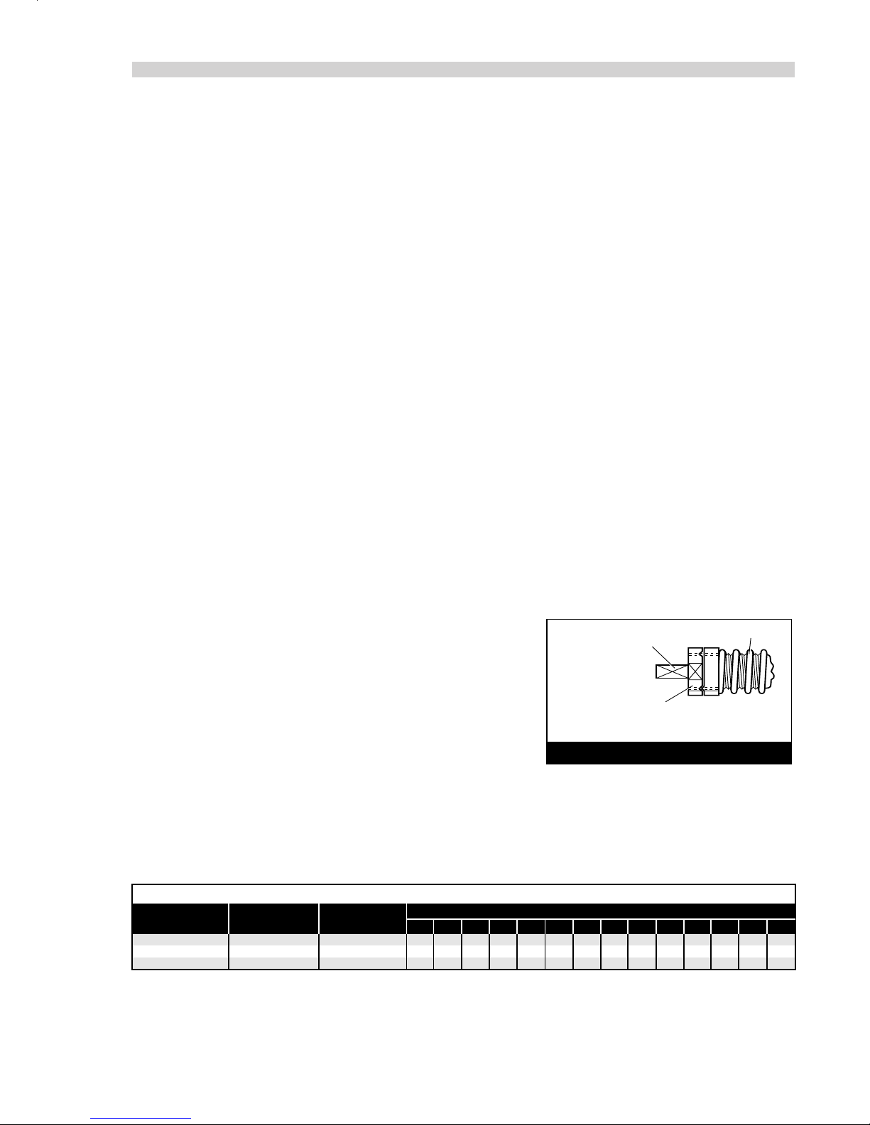
ADJUSTMENT NUT SET
LEVEL WITH FACE AT END
OF THREAD ON CLUTCH SPINDLE
RESETTING CLUTCH TORQUE
CLUTCH SPRING
SQUARE DRIVE ON END
OF CLUTCH SPINDLE
CLUTCH
Place housing and bush assembly 1in vice fitted with soft jaws.
Unscrew clutch housing 34 (left hand thread) and remove bush 35 from clutch housing 34.
Withdraw the clutch assembly, taking care not to bend push rod 43. Pull out push rod (long) 43.
Remove the tool from the vice and gently tap on the front end of assembly to remove needle roller 61 and push rod (short) 65.
Holding the square drive end of clutch spindle 31, unscrew adjustment nut 28.
Pull off adjustment lock washer 29 and spring 30.
Depress spring 42 and remove pin 41.
Remove collar 40 and three balls 38.
Remove split retaining ring halves 39.
Move front jaw 33 relative to clutch spindle 31 until small hole in side of front jaw 33 is aligned with track of the balls in clutch
spindle 31.
Ten balls 36 will become visible through small hole in front jaw 33.
Gently tap front jaw 33, allowing the ten balls to fall out of hole in the front jaw, (as each ball is ejected, turn front jaw 33 on clutch
spindle 31 to align next ball with hole).
Insert small rod through centre of front jaw 33 and tap out clutch spindle 31.
Remove drive jaw 32, key 37 and spring 42.
Assemble in reverse order to dismantling.
Reset clutch torque in the following manner, (see diagram opposite):
Place square drive on end of clutch spindle 31 in vice, engaging
approximately 10 mm in vice jaws. This allows access for spanner entry.
Using the spanner, unscrew adjustment nut 28 until it is level with the
end of the thread of the clutch spindle. Torque can then be increased/
decreased as dictated by fastener type and size by turning the adjustment
nut clockwise/anticlockwise as appropriate. Use the data in the table below
to know how many turns to give a particular torque.
Use the data in the table below to know how many turns give a particular torque.
7556 CLUTCH DETAILS
SPRING
PART Nº SPRING
COLOUR
1234567891011121314
-34425160 - - -------
5
7.5
10
12.5
15
17.5
20
22.5
25 28 31 34 - -
--5678910111213141516
Nº OF TURNS/lb f ins
UNSET CLUTCH
PART Nº
08556-00390 08572-00407 OXIDE BLACK
08556-00380 08556-00412 SILVER
08557-00380 08557-00202 COPPER
■
■
■
■
■
■
■
■
■
■
■
■
■
■
■
■
■
■
12
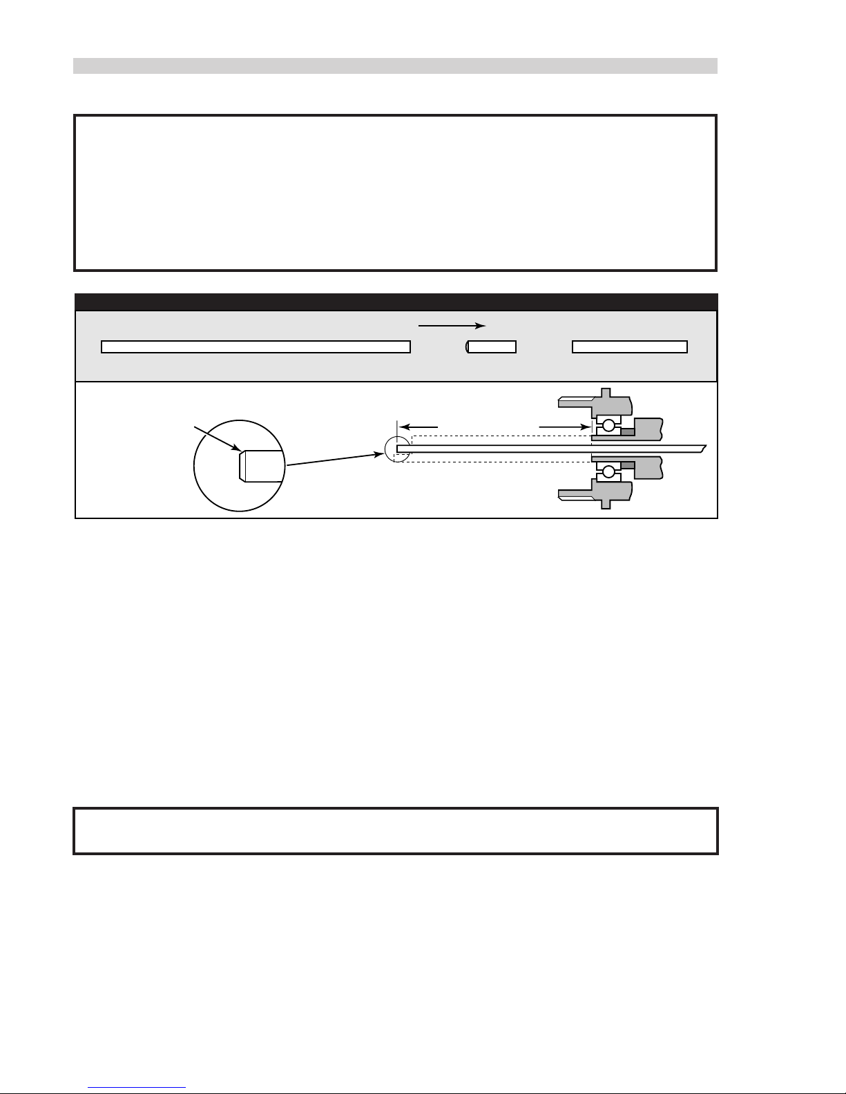
It is imperative that the reverse control rods are fitted in the correct sequence (see diagram opposite) to ensure correct tool
function. When renewing the long push rod, it is necessary to trim the overall length to give a protrusion of 37.85mm
(1.49”)/38.1mm (1.5”) of the push rod above the front face of the output square drive spindle of the final gearbox.
A gauge (part number 07900-00424) is used to achieve this.
This operation should be carried out with the air supply connected to the tool. Do not operate the trigger during this
operation. When the rod has been trimmed to the correct length, carefully remove the sharp edge left with either a
0.4mm(.015”) radius or 45°chamfer. Take care not to bend or damage the new push rod.
I M P O R T A N T
LONG PUSH ROD SHORT PUSH ROD
REAR OF TOOL
37.85mm/38.1mm
(1.49”)/(1.5”)
0.4mm (.015’) RAD
OR 45°CHAMFER
NEEDLE ROLLER
FITTING NEW REVERSE CONTROL RODS
■
■
■
■
■
■
■
■
■
■
■
■
■
■
■
■
■
■
■
■
HANDLE ASSEMBLY
Replace handle and brush assembly 1in soft jaw vice.
Using spanner on ring gear 45, remove front gear assembly.
Using spanner on housing 26, remove inner gear assembly.
Remove ‘0’ ring 19 and spacer 18 from handle and brush assembly 1and pull out the motor assembly. (It may be necessary to tap
the front end of handle and bush assembly 1on a wooden block until the motor assembly slides out).
Unscrew silencer retainer assembly 9and remove perforated washer 10, silencer body 12 and silencer element 11.
Unscrew nipple 8from adaptor 7.
Unsrew adaptor 7from handle and brush assembly 1and remove filter 6.
Tap out pin 15 and carefully pull out the trigger assembly, (take care not to damage ‘0” rings).
Support trigger 17 and carefully drive out pin 16 taking care not to damage or bend valve 3.
Separate trigger 17 from valve 3and remove ‘0” ring 14, three ‘0’ rings 2from valve body 13 and ‘o’rings 4& 5from valve 3.
Unscrew knob 76 and remove ‘0’ ring 68 from handle and bush assembly 1.
Remove screw 74 and washer 75.
Lightly tap end plate 71 to break the Loctite seal between end plate 71 and valve assembly 66.
Remove end plate 71, taking care not to damage pins 73.
Remove ‘0’ ring 72 and spring 70.
Push valve assembly 66 out of hanfle and bush assembly 1.
I M P O R T A N T
Valve assembly 66 is a manufacturer supplied assembly and MUST NOT be dismantled
Remove ‘0’ ring 67 from valve assembly 66.
Remove ‘0’ ring 69 from valve bush but do not attempt to remove the valve bushing from handle and bush assembly 1.
Assemble in reverse order of dismantling.
When replacing screw 74 and washer 75 ensure thread sealant is used on screw threads.

I M P O R T A N T
Check the tool against daily and weekly servicing.
13
■
■
■
■
■
■
■
■
■
■
■
■
■
■
■
■
■
■
■
■
■
■
■
■
■
■
■
■
■
■
■
FRONT GEAR ASSEMBLY (previously removed from handle assembly).
Hold ring gear 45 and tap out internal asembly from front end.
Remove two bearing 25 and spacers 50 and 47 from planet gear spindle 46.
Tap out two shafts 28 and thirty needles 27 and remove two planet gears 49 and drive gear 48.
Assemble in reverse order of dismantling.
REAR GEAR ASSEMBLY
MOTOR ASSEMBLY (previously removed from handle assembly).
Pull off spacer 53.
Hold housing 26 and push out internal assembly from the front end.
Remove two bearings 25 and spacers 20 & 23. from planet gear spindle 24.
Push out two shafts 52 together with thirty needles 21.
Take out two planet gears 49 and drive gear 22.
Using circlip pilers, remove circlip 51 from housing 26.
Assemble in reverse order of dismantling.
Remove locating pin 56 from lower end plate 55.
Hold lower end plate 55 and tap splined end of rotor 59 with a soft hammer so as not to damage splines.
Remove lower end plate 55 and bearing 54 from rotor 59.
Remove cylinder 58 complete with pin 57 and pin 62.
Remove five rotor blades 61 from rotor 59.
Support rear end plate 63 using a piece of tube with a bore diameter as close as possibl to largest diameter of rotor 59, then tap
the non-splined end of the rotor to remove it from rear end plate 63 and bearing 64.
Using a suitable punch, tap out bearing 54 from lower end plate55, bearing 64 and rear end plate 63.
When assembling, make sure that locating pin 58 in lower end plate 55 locates in keyway in the front end bore of the handle.
Pay special attention to lower end plate 55 and rear end plate 63, ensuring they are free from burrs and surface marking. If
necessary, lap faces that abut cylinder 58 on a flat fine grade abrasive paper.
Press fir bearings 54 & 64 into lower and rear end plates 55 & 63.
Support bearing 64 in rear end plate 63 on its inner ring and using a soft hammer, tap rotor 59 on its splined end until the rotor
locates against rear end plate 63.
Support inner face of rear end plate 63 as close as possible to largest diameter of rotor 59.
Tap non-splined end of rotor 59 until a clearance of 0.040 mm (0.0015 in) to 0.065 mm (0.0025 in) is obtained between inner
face of rear end plate 63 and rotor 59.
Check clearance by pulling rotor 59 away from rear end plate 63 and bearing 64.
Spin rotor 59 ensuring that it rotates freely in rear end plate bearing 64.
Locate cylinder 58 with locating pin 56 to rear end plate 63 and check ports in rear end plate 63 align with ports in cylinder 58.
Insert five rotor blades 60 into rotor 59.
Fit lower end plate 55 to cylinder 58 via locating pin 56.
Ensure rotor 59 spins freely.
Fit motor in reverse order of removal (see handle assembly).

GENERAL ASSEMBLY OF BASE TOOL 07556-00400
14
13
38
37
36
35 33 32
34
41 42 43 44
31 30
29
28
27
26
25 23 21 19
24 22 20 18
17 16 15
14
12
11
10
98
45
46
47
48
49 51 53 55 57 59 61 63 65 67 69 71 72
73
74
75
76
1
3
5
2
4
6
7
50 52 54 56 58 60 62 64 66 68 70
39
40

15
01 08556-00423 HANDLE AND BUSH ASSEMBLY 1-
02 08415-00207 'O' RING 3 3
03 08556-00417 VALVE 1 1
04 08434-00202 'O' RING 1 1
05 08441-00402 'O' RING 2 4
06 08415-00201 FILTER 1 2
07 08415-00202 ADAPTOR 1 -
08 08433-00221 NIPPLE 1 -
09 08415-00203 SILENCER RETAINER ASSEMBLY 1-
10 08432-00201 PERFORATED WASHER 1-
11 08415-00204 SILENCER ELEMENT 12
12 08415-00205 SILENCER BODY 1-
13 08520-00212
VALVE BODY
11
14 08520-00215 'O' RING 1 2
15 08524-00207 PIN 1 2
16 08433-00233 PIN 1 2
17 08281-00405 TRIGGER 1 -
18 08430-00215 SPACER 1 -
19 08522-00205
'O' RING
1-
20 08434-00201 SPACER 1 -
21 08434-00207 NEEDLE 30 -
22 08434-00203 DRIVE GEAR 1 -
23 08434-00205 SPACER 1 -
24 08556-00414 PLANET GEAR SPINDLE 1-
25 08430-00705 BEARING 4 -
26 08430-00708 HOUSING 1 -
27 08434-00207 NEEDLE 30 -
28 08434-00208 SHAFT 2 -
29 08430-00229 ADJUSTMENT NUT 1-
30 08556-00409 ADJUSTMENT LOCK WASHER 1-
31 08556-00413 PUSH ROD (LONG) 1-
32 08556-00407 PIN 1 -
33 08556-00405 RETAINING RING HALF 2-
34 08556-00404 DRIVE JAW 1 -
35 08556-00401 FRONT JAW 1 -
36 08556-00402 CLUTCH HOUSING 1-
37 08430-00223 KEY 1 -
38 08430-00221
3
/
32
DIA. BALL 10 -
39 08556-00403 BUSH 1 -
40 08556-00410
5
/
16
DIA. BALL 3 -
41 08556-00406 COLLAR 1 -
42 08556-00411 SPRING 1 -
43 08557-00202 CLUTCH SPRING 35-85lb. (COPPER) 1-
08572-00407 CLUTCH SPRING 5-16lb. (OXIDE BLACK) 1-
08556-00412 CLUTCH SPRING 12-35lb. (SILVER) 1-
44 08556-00408 CLUTCH SPINDLE 1-
45 08430-00801 RING GEAR 1 -
46 08443-00401 PLANET GEAR SPINDLE 1-
47 08443-00402 SPACER 1 -
48 08434-00203 DRIVE GEAR 1 -
49 08434-00206 PLANET GEAR 4 -
50 08434-00201 SPACER 1 -
51 08430-00707 CIRCLIP 1 -
52 08434-00208 SHAFT 1 -
53 08430-00706 SPACER 1 -
54 08430-00601 BEARING 1 -
55 08430-00602 LOWER END PLATE 1-
56 08435-00202 LOCATING PIN 1 -
57 08433-00233 PIN 1 -
58 08435-00214 CYLINDER 1 -
59 08556-00415
ROTOR
1-
60 08556-00418 NEEDLE ROLLER 1 3
61 08430-00608 ROTOR BLADE 5 -
62 08435-00203 PIN 1 -
63 08433-00214 REAR END PLATE 1-
64 08430-00606 BEARING 1 -
65 08556-00416 PUSH ROD (SHORT) 13
66 08556-00420 VALVE ASSEMBLY 1-
67 08435-00209 'O' RING 1 -
68 08435-00204 'O' RING 1 2
69 08415-00217 'O' RING 1 -
70 08556-00425 SPRING 1 -
71 08556-00422 END PLATE 1 -
72 08556-00424 'O' RING 1 -
73 08415-00209 PIN 2 -
74 08415-00221 SCREW 1 -
75 08415-00220 WASHER 1 -
76 08415-00421 KNOB 1 -
ITEM PART Nº DESCRIPTION QTY REC.
SPARES ITEM PART Nº DESCRIPTION QTY REC.
SPARES
07556-00200 PARTS LIST

F A U L T D I A G N O S I S T A B L E
FA U L T D I A G N O S I S
16
SYMPTOM POSSIBLE CAUSE REMEDY
Tool reverses ➝Worn thrust bearing or thrust washers ➝Replace
before Insert ➝Dirty insert threads ➝Change batch of inserts
is Placed ➝Worn drive screw ➝Replace
➝Lack of lubrication on drive screw ➝Lubricate drive screw properly (see page 6)
(Standard Nutserts only)
➝Thrust spring not fitted ➝Fit thrust spring
➝Clutch torque setting too low ➝Adjust to correct setting
➝Insufficient pressure/volume of air ➝Check air supply/fittings
Tool runs slowly ➝Insufficient air pressure ➝Adjust air pressure at base of handle. 5 - 8 bar maximum.
➝Incorrect bore of hose ➝Ensure bore of hose is 6.4mm minimum
➝Insufficient air volume ➝Ensure there is no restriction in the air supply or connections
➝Tool not properly lubricated internally ➝Lubricate as per instructions
Tool fails to start ➝Tool not properly lubricated ➝Lubricate then depress trigger several times
➝Restricted air pressure/volume ➝Ensure there is no restriction in the air supply
Tool runs ➝Push rod too long ➝Replace with one of correct length
permanently ➝Insufficient air supply ➝Adjust air pressure/volume
in reverse mode
Tool runs ➝Push rods/needle roller missing ➝Replace where necessary
permanently ➝Air leak around screw 73 ➝Seal with thread sealant
in forward mode ➝Push rod too short ➝Replace
Inserts not ➝Torque setting too low ➝Adjust to correct setting
pulling up ➝Insufficient air pressure/volume ➝Adjust air pressure/volume
➝Inserts out of grip ➝Select correct insert
➝Lack of lubrication on insert ➝Change batch of inserts
➝Lack of lubrication on drive screw ➝Lubricate drive screw correctly (see page 6)
(Standard Nutserts only)
➝Insert thread restricted ➝Change Inserts
➝Drive screw thread worn ➝Replace drive screw
➝Incorrect insert/drive screw ➝Replace with correct insert/drive screw
Standard Nutserts ➝Dirty Nutserts ➝Clean Nutserts
centres falling out ➝Clutch torque setting too low ➝Adjust to correct setting
➝Application thickness below minimum ➝Change to correct Insert
recommended grip
➝Oversize hole in application ➝Correct hole size in application
Worn drive screws ➝Clutch torque setting too high ➝Adjust to correct setting
➝Drive screw not lubricated ➝ Lubricate drive screw regularly when using Standard Nutserts
➝Inserts not lubricated ➝Change batch of inserts
➝Tool not held correctly ➝Ensure tool is held square to application
➝Incorrect insert/drive screw threads ➝Replace with correct insert/drive screw
➝Restricted insert threads ➝Change batch of inserts

17
® © ™ Products mentioned and /or illustrated within this publication are subject to patent, design or copyright protection in many countries.
Engineered Fastening and Assembly Systems
Declaration of Conformity
We, Avdel UK Limited, Mundells, Welwyn Garden City, Herts, AL7 1EZ
declare under our sole responsibility that the product
type 07556
Serial Nº ..............................................
to which this declaration relates is in conformity with the following standards or other formative documents
EN292 part 1 and part 2
ISO 8662 part 1 and part 7
ISO 3744 and PNEUROP test code PN8TC1
ISO PREN792 part 6
following the provisions of the Machine Directive 98/37/EC
This box contains a power tool which is in conformity with Machines Directive
98/37/EC. The ‘Declaration of Conformity’ is contained within.
Welwyn Garden City - date of issue A. Seewraj
Product Engineering Manager - Automation Tools

Manual No. Issue Change Note No.
07900-00666
B07/325
© Avdel UK Limited 2007
AUSTRALIA
Acument Australia Pty Ltd.
891 Wellington Road
Rowville, Victoria 3178
Tel: +61 3 9765 6400
Fax: +61 3 9765 6445
Email: [email protected]
CANADA
Avdel Canada, a Division of Acument
Canada Limited
87 Disco Road
Rexdale
Ontario M9W 1M3
Tel: +1 416 679 0622
Fax: +1 416 679 0678
Email: [email protected]
CHINA
Acument China Ltd.
RM 1708, 17/F., Nanyang Plaza,
57 Hung To Rd., Kwun Tong
Hong Kong
Tel: +852 2950 0631
Fax: +852 2950 0022
Email: [email protected]
FRANCE
Avdel France S.A.S.
33 bis, rue des Ardennes
BP4
75921 Paris Cedex 19
Tel: +33 (0) 1 4040 8000
Fax: +33 (0) 1 4208 2450
Email: [email protected]
GERMANY
Avdel Deutschland GmbH
Klusriede 24
30851 Langenhagen
Tel: +49 (0) 511 7288 0
Fax: +49 (0) 511 7288 133
Email: [email protected]
ITALY
Avdel Italia S.r.l.
Viale Lombardia 51/53
20047 Brugherio (MI)
Tel: +39 039 289911
Fax: +39 039 2873079
Email: [email protected]
JAPAN
Acument Japan Kabushiki Kaisha
Center Minami SKY,
3-1 Chigasaki-Chuo, Tsuzuki-ku,
Yokohama-city, Kanagawa Prefecture
Japan 224-0032
Tel: +81 45 947 1200
Fax: +81 45 947 1205
Email: [email protected]
SINGAPORE
Acument Asia Pacific (Pte) Ltd.
#05-03/06 Techlink
31 Kaki Bukit Road 3
Singapore, 417818
Tel: +65 6840 7431
Fax: +65 6840 7409
Email: [email protected]
SOUTH KOREA
Acument Korea Ltd.
212-4, Suyang-Ri,
Silchon-Eup, Kwangju-City,
Kyunggi-Do, Korea, 464-874
Tel: +82 31 798 6340
Fax: +82 31 798 6342
Email: [email protected]
SPAIN
Avdel Spain S.A.
C/ Puerto de la Morcuera, 14
Poligono Industrial Prado Overa
Ctra. de Toledo, km 7,8
28919 Leganés (Madrid)
Tel: +34 (0) 91 3416767
Fax: +34 (0) 91 3416740
Email: [email protected]
UNITED KINGDOM
Avdel UK Limited
Pacific House
2 Swiftfields
Watchmead Industrial Estate
Welwyn Garden City
Hertfordshire
AL7 1LY
Tel: +44 (0) 1707 292000
Fax: +44 (0) 1707 292199
Email: [email protected]
USA
Avdel USA LLC
614 NC Highway 200 South
Stanfield,
North Carolina 28163
Tel: +1 704 888-7100
Fax: +1 704 888-0258
Email: [email protected]
www.avdel-global.com
Table of contents
Other Avdel Power Tools manuals

Avdel
Avdel Avbolt 07220 User manual

Avdel
Avdel GenesisG2-s User manual

Avdel
Avdel TX2000 User manual

Avdel
Avdel 7900 User manual

Avdel
Avdel 7557 User manual

Avdel
Avdel 7391 User manual

Avdel
Avdel 74401 User manual

Avdel
Avdel Genesis G2LB User manual

Avdel
Avdel Genesis 4 User manual

Avdel
Avdel 74100 User manual

Avdel
Avdel Genesis G3 User manual

Avdel
Avdel 71404 User manual

Avdel
Avdel Genesis nG2s User manual

Avdel
Avdel G3LB Tool User manual

Avdel
Avdel Genesis G2LB User manual

Avdel
Avdel 7271 User manual

Avdel
Avdel 74100 User manual

Avdel
Avdel 7555 User manual

Avdel
Avdel Genesis G2LB User manual

Avdel
Avdel Genesis G2LB User manual


