Avdel 74100 User manual

Instruction Manual
Threaded Insert Power Tool
74100


3
Contents
Safety Rules 4
Tool Specifications 5
Tool Dimensions 5
Intent of Use
Tool Selection 6
Putting into Service
Air supply 7
Operating Procedure 7
Clutch Adjustment 8
Accessories 8
Nose Assemblies
Fitting Instructions 9
Servicing Instructions 9
Nose Assembly Components 10
Servicing the Tool
Daily Servicing 11
Weekly Servicing 11
Safety Data (Grease) 12
Maintenance
Control Valve Assembly 13
Clutch Assembly 14 & 15
Motor Assembly 16
Gearbox Assembly 17
Setting the Push Rod 18
General Assembly of Base Tool 20
Parts List 21
Troubleshooting 22 & 23
Avdel UK Limited policy is one of continuous product development and improvement and we reserve the right to change the specification of any product without prior notice.
Warranty
Avdel installation tools carry a 12 month warranty against defects caused by faulty materials or
workmanship, the warranty period commencing from the date of delivery confirmed by invoice or delivery
note.
The warranty applies to the user/purchaser when sold through an authorised outlet, and only when used for
the intended purpose. The warranty is invalidated if the installation tool is not serviced, maintained and
operated according to the instructions contained in the Instruction and Service Manuals.
In the event of a defect or failure, and at its sole discretion, Avdel undertakes only to repair or replace faulty
components.

4
Safety Rules
1Do not use outside the design intent.
2Do not use equipment with this tool other than that recommended and supplied by Avdel UK Limited.
3Any modification undertaken by the customer to the tool/machine, nose assemblies, accessories or any equipment
supplied by Avdel UK Limited or their representatives, shall be the customer’s entire responsibility. Avdel UK Limited
will be pleased to advise upon any proposed modification.
4The tool/machine must be maintained in a safe working condition at all times and examined at regular intervals for
damage and function by trained competent personnel. Any dismantling procedure shall be undertaken only by
personnel trained in Avdel UK Limited procedures. Do not dismantle this tool/machine without prior reference to the
maintenance instructions. Please contact Avdel UK Limited with your training requirements.
5The tool/machine shall at all times be operated in accordance with relevant Health and Safety legislation. In the U.K.
the “Health and Safety at Work etc. act 1974” applies. Any question regarding the correct operation of the
tool/machine and operator safety should be directed to Avdel UK Limited.
6The precautions to be observed when using this tool/machine must be explained by the customer to all operators.
7Always disconnect the airline from the tool/machine inlet before attempting to adjust, fit or remove a nose
assembly.
8Do not operate a tool/machine that is directed towards any person(s).
9Ensure that vent holes do not become blocked or covered and that hoses are always in good condition.
10 The operating pressure shall not exceed 6.3 bar - 94.5 lbf/in2.
11 Do not operate the tool without full nose equipment in place.
12 When using the tool, the wearing of safety glasses is required both by the operator and others in the vicinity to
protect against fastener projection, should a fastener be placed ‘in air’. We recommend wearing gloves if there are
sharp edges or corners on the application.
13 Take care to avoid entanglement of loose clothes, ties, long hair, cleaning rags etc. in the moving parts of the tool
which should be kept dry and clean for best possible grip.
14 When carrying the tool from place to place keep hands away from the trigger/lever to avoid inadvertent start up.
15 Always adopt a firm footing or a stable position before operating the tool and be aware of a torque reaction on the
hands when the tool is operating, particularly during the reversing sequence. Grip the tool firmly to be able to
counter the torque reaction, but not too tightly.
16 Keep hands away from the rotating drive screw and the nose end of the tool. If a fastener becomes jammed on the
drive screw, shut off the air supply and drain the supply line to the tool before attempting to dislodge it.
17 The tool is not electrically insulated.
18 This tool is not designed for use in combustible or explosive atmospheres.
This instruction manual must be read with particular attention to the following safety rules, by any
person installing, operating, or servicing this tool.
5
Tool Specification
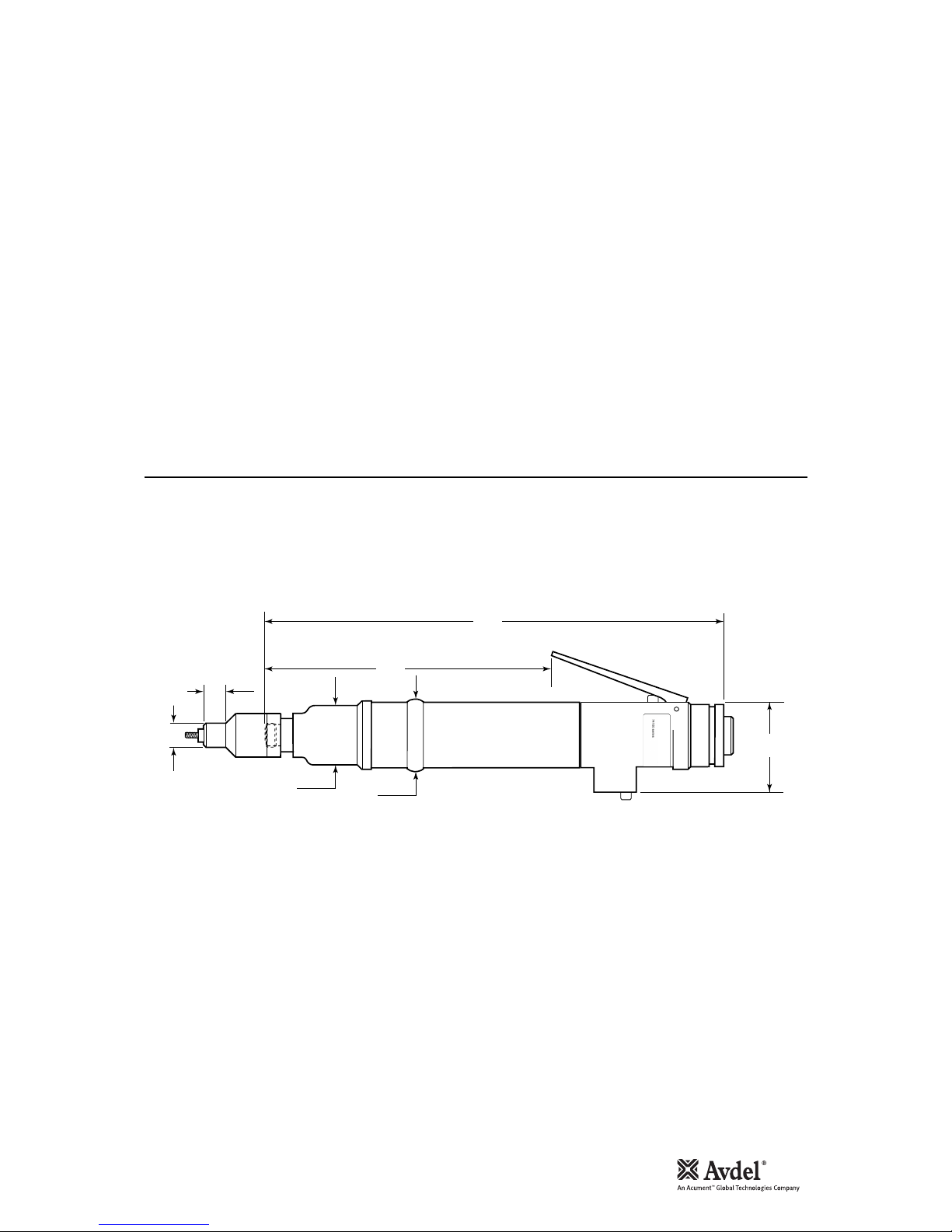
Tool Dimensions
Specifications
Air Pressure Minimum - Maximum 4-6.3 bar (60-94.5 lbf/in2)
Free Air Volume Required @ 6.3 bar / 94 lbf/in27.5 litres/sec
Motor Speed @ 75 lb/in2minimum 1100 rpm (clockwise)
Cycle time Approx 3 seconds
Noise Level 75 dB(A)
Weight Without nose equipment 1.076 kg (2.37 lb)
Vibration Less than 2.5 m/s2(8 ft/s2 )
35.6
1.401 40
1.575
A
B
49
1.929
180
7.086
273
10.75
Dimensions shown in bold are millimetres. Other dimensions are in inches

6
Intent of Use
Tool Selection
The pneumatic 74100 type tool is designed to place Avdel®threaded inserts at high speed making it ideal for batch or
flow-line assembly in a wide variety of applications throughout all industries.
Use the selection table below to select a complete tool which will be fitted with the correct nose assembly for the
threaded insert selected. ‘A’ and ‘B’ dimensions will help you assess the accessibility of your application.
It is also possible to order the base tool only (part number 74100-12000). For details of Nose Assemblies see page 10.
4 UNC 7 - 9 84100-15020 13 11 1/27/16 07556-09954 74100-01054
6 UNC 16 - 18 84100-15010 13 11 1/27/16 07556-09956 74100-01056
8 UNC 16 - 18 84100-15010 13 12 1/215/32 07556-09958 74100-01058
4 UNF 7 - 9 84100-15020 13 11 1/27/16 07556-09974 74100-01074
6 UNF 16 - 18 84100-15010 13 11 1/27/16 07556-09976 74100-01076
8 UNF 16 - 18 84100-15010 13 12 1/215/32 07556-09978 74100-01078
6 BA 7 - 9 84100-15020 13 11 1/27/16 07556-09936 74100-01036
4 BA 16 - 18 84100-15010 13 11 1/27/16 07556-09934 74100-01034
M3 7 - 9 84100-15020 13 11 1/27/16 07556-09983 74100-01083
M4 16 - 18 84100-15010 13 11 1/27/16 07556-09984 74100-01084
8 UNC 16 - 18 84100-15010 13 10 1/213/32 07552-09558 74100-02058
8 UNF 16 - 18 84100-15010 13 10 1/213/32 07552-09578 74100-02078
M3 16 - 18 84100-15010 13 19 1/23/407552-09583 74100-02083
M4 16 - 18 84100-15010 13 17 1/221/32 07552-09584 74100-02084
M4 16 - 18 84100-15010 13 15 1/219/32 07556-09184 74100-04084
3/16 BSW 20 - 25 84100-15000 13 12 1/215/32 07556-09816 74100-00016
4 UNC 5 - 7 84100-15020 13 12 1/215/32 07556-09854 74100-00054
6 UNC 9 - 11 84100-15010 13 12 1/215/32 07556-09856 74100-00056
8 UNC 13 - 15 84100-15010 13 10 1/213/32 07556-09858 74100-00058
10 UNC 20 - 25 84100-15000 13 12 1/215/32 07556-09850 74100-00050
6 UNF 9 - 11 84100-15010 13 12 1/215/32 07556-09876 74100-00076
8 UNF 13 - 15 84100-15010 13 10 1/213/32 07556-09878 74100-00078
10 UNF 20 - 25 84100-15000 13 12 1/215/32 07556-09870 74100-00070
6 BA 5 - 7 84100-15020 13 12 1/215/32 07556-09836 74100-00036
4 BA 9 - 11 84100-15010 13 12 1/215/32 07556-09834 74100-00034
2 BA 20 - 25 84100-15000 13 12 1/215/32 07556-09832 74100-00032
M3 5 - 7 84100-15020 13 12 1/215/32 07556-09883 74100-00083
M4 13 - 15 84100-15010 13 10 1/213/32 07556-09884 74100-00084
M5 20 - 25 84100-15000 13 12 1/215/32 07556-09885 74100-00085
M4 16 - 18 84100-15010 13 15 1/219/32 07556-09184 74100-04084
M4 16 - 18 84100-15010 13 18 1/223/32 07556-09284 74100-06084
74100 TOOL SELECTION
NOSE (see drawing opposite for A & B)
TORQUE
SETTING (lbf ins)
Ø
COMPLETE
TOOL PART Nº
NOSE ASSY PART N º
A (mm)
INSERT
NAME & SERIES B (mm) A (in) B (in)
UNSET
CLUTCH PART Nº
THIN SHEET
NUTSERT®
(9650)
SUPERSERT®
(FB00)
LG. FLANGE
HEXSERT
®
(9498)
STANDARD
NUTSERT®
(9500)
(9538)
L/F THIN SHEET
NUTSERT
®
(9698)
HEXSERT
®
(9688)

7
Air Supply
Operating Procedure
Putting into Service
All tools are operated with compressed air at an optimum pressure of 5.5 bar. We recommend the use of pressure regulators and
automatic oiling/filtering systems on the main air supply. These should be fitted within 3 metres of the tool (see diagram below) to
ensure maximum tool life and minimum tool maintenance.
Air supply hoses should have a minimum working effective pressure rating of 150% of the maximum pressure produced in the system
or 10 bar, whichever is the highest. Air hoses should be oil resistant, have an abrasion resistant exterior and should be armoured
where operating conditions may result in hoses being damaged. All air hoses MUST have a minimum bore diameter of 6.4 millimetres
or 1/4 inch.
Read servicing daily details page 11.
8
6
4
2
0
10
12
14
16
TAKE OFF POINT
FROM MAIN SUPPLY
STOP COCK
(USED DURING MAINTENANCE
OF FILTER/REGULATOR
OR LUBRICATION UNITS)
MAIN SUPPLY
DRAIN POINT
PRESSURE REGULATOR
AND FILTER
(DRAIN DAILY)
LUBRICATOR
3
M
E
T
R
E
S
IMPORTANT
When placing Standard Nutserts, lubricate the drive screw of the tool every 25 placings. This is best
achieved by wiping the drive screw with a sponge soaked with STP Lubricant part number 07992-00013.
OPTION 1
•Ensure that the correct nose equipment is fitted.
•Connect the tool to the air supply.
•Place the insert into the prepared hole of the application.
•Locate the drive screw of the tool into the insert.
•Operate the lever. The drive screw will screw into and
collapse the insert, then automatically reverse out.
OPTION 2
•Ensure that the correct nose equipment is fitted.
•Connect the tool to the air supply.
•Screw the insert lip first onto the drive screw of the tool.
•With the insert on the tool, locate it into the prepared
hole of the application.
•Operate the lever. The drive screw will screw into and
collapse the insert, then automatically reverse out.

8
Clutch Adjustment
Accessories
Putting into Service
If you have ordered a complete tool the clutch will be set for the specified insert.
When purchased as a spare part, the clutch is supplied unset.
Correct clutch setting is necessary to ensure optimum deformation of the insert. If the deformation is insufficient (clutch
torque too low) the insert will rotate in the application. If the deformation is excessive (clutch torque too high) thread distortion
will occur and extensive wear on the drivescrew, may lead to fracture.
For details on how to adjust the clutch refer to maintenance instructions referring to the clutch on page 15.
Two different accessories are available to make the connection to your air supply:
Hose Connector
part nº 07005-00276
Hose Assembly
part nº 07008-000324
TO FIT 6.4 mm (1/4") BORE PIPE
1/4" BSP L = 137 cm

9
Fitting Instructions
Servicing Instructions
Nose Assemblies
Nose assemblies are specifically designed for each size and type of insert. If you have purchased a complete tool, it will already be
fitted with the correct nose assembly for your insert.
It is essential that the correct nose assembly is fitted prior to operating the tool. By knowing your original complete tool part number
or the details of the insert to be placed, you will be able to order a new complete nose assembly using the selection table page 10.
IMPORTANT
The air supply must be disconnected when fitting or removing nose assemblies unless specifically instructed
otherwise.
Before fitting the nose equipment, ensure the clutch on the tool is set to the correct torque for the insert being placed. (Torque values
are on page 6.)
•Where applicable, insert sleeve 8and thrust spring 9into nose housing 2.
•Coat thrust washers 3and thrust bearing 4with high pressure grease (eg. Shell Alvania E.P.I.) and locate them in the order shown
below into the nose housing 2.
•Where applicable, fit spacer 5through thrust washers and thrust bearings.
•Insert drive screw 1through the above assembly.
•Fit drive shaft 6into the hexagon hole in the drive screw head.
•Insert stop 11 and spring 10 into the front of the base tool.
•Screw adaptor 7into clutch housing of the base tool (left hand thread).
•Offer up the nose assembly to the adaptor. It will be necessary to rotate the drive screw by hand to line up the hexagon on the
drive shaft 6with the hexagonal hole in the front jaw of the base tool.
•Screw the nose housing 2onto the adaptor 7and tighten with a spanner (left hand thread).
289
1610
34 3 5
11 7
Nose assemblies should be serviced at weekly intervals.
•Remove the complete nose assembly using the reverse procedure to the ‘Fitting Instructions’.
•Any worn or damaged part should be replaced.
•Particularly check wear on drivescrew, thrust washers and thrust bearing.
•Lubricate thrust washers and thrust bearings with high pressure grease (eg Shell Alvania E.P.I.)
•Check springs are not distorted.
•Assemble according to fitting instructions.

10
Nose Assembly Components
Nose Assemblies
The table below lists all nose assemblies available. Each nose assembly represents a unique assembly of components which can be
ordered individually. Components numbers refer to the text and illustration opposite. We recommend some stock as items will need
regular replacement. Read the nose assemblies servicing instructions opposite carefully. All nose assemblies also include spring 10
part number 07430-08202 and stop 11 part number 07430-08203.
61 7
NOSE ASSY 2435 89
07552-09558 07001-00318 07552-07701 07007-00080 07007-00077 07521-08809 07521-08804 07443-08001 - -
07552-09578 07001-00319 07552-07701 07007-00080 07007-00077 07521-08809 07521-08804 07443-08001 - -
07552-09583 07001-00325 07552-07709 07007-00080 07007-00077 07520-08803 07520-08802 07443-08001 - -
07552-09584 07001-00326 07552-07705 07007-00080 07007-00077 07521-08810 07521-08805 07443-08001 - -
07556-09184 07001-00326 07552-06804 07007-00080 07007-00077 07521-08810 07521-08805 07443-08001 07552-08804 07440-08002
07556-09284 07001-00326 07521-08984 07007-00080 07007-00077 07521-08810 07521-08805 07443-08001 07521-08901 07440-08002
07556-09816 07001-00320 07440-06805 07007-00080 07007-00077 07521-08808 07521-08803 07443-08001 - -
07556-09832 07001-00321 07440-06805 07007-00080 07007-00077 07521-08808 07521-08803 07443-08001 - -
07556-09834 07001-00315 07440-06304 07007-00080 07007-00077 07521-08807 07521-08802 07443-08001 - -
07556-09836 07001-00276 07440-06306 07007-00080 07007-00077 07520-08803 07520-08801 07443-08001 - -
07556-09850 07001-00300 07440-06805 07007-00080 07007-00077 07521-08808 07521-08803 07443-08001 - -
07556-09854 07001-00313 07440-06306 07007-00080 07007-00077 07520-08803 07520-08801 07443-08001 - -
07556-09856 07001-00316 07440-06304 07007-00080 07007-00077 07521-08807 07521-08802 07443-08001 - -
07556-09858 07001-00318 07440-06508 07007-00080 07007-00077 07521-08809 07521-08804 07443-08001 - -
07556-09870 07001-00301 07440-06805 07007-00080 07007-00077 07521-08808 07521-08803 07443-08001 - -
07556-09876 07001-00317 07440-06304 07007-00080 07007-00077 07521-08807 07521-08802 07443-08001 - -
07556-09878 07001-00319 07440-06508 07007-00080 07007-00077 07521-08809 07521-08804 07443-08001 - -
07556-09883 07001-00325 07440-06306 07007-00080 07007-00077 07520-08803 07520-08802 07443-08001 - -
07556-09884 07001-00326 07440-06508 07007-00080 07007-00077 07521-08810 07521-08805 07443-08001 - -
07556-09885 07001-00256 07440-06805 07007-00080 07007-00077 07521-08808 07521-08806 07443-08001 - -
07556-09934 07001-00315 07440-08804 07007-00080 07007-00077 07521-08807 07521-08802 07443-08001 07521-08801 07440-08002
07556-09936 07001-00276 07440-08803 07007-00080 07007-00077 07520-08803 07520-08801 07443-08001 07440-08003 07440-08002
07556-09954 07001-00313 07440-08803 07007-00080 07007-00077 07520-08803 07521-08801 07443-08001 - -
07556-09956 07001-00316 07440-08804 07007-00080 07007-00077 07521-08807 07521-08802 07443-08001 - -
07556-09958 07001-00318 07440-08808 07007-00080 07007-00077 07521-08809 07521-08804 07443-08001 - -
07556-09974 07001-00314 07440-08803 07007-00080 07007-00077 07520-08803 07520-08801 07443-08001 - -
07556-09976 07001-00317 07440-08804 07007-00080 07007-00077 07521-08807 07521-08802 07443-08001 - -
07556-09978 07001-00319 07440-08808 07007-00080 07007-00077 07521-08809 07521-08804 07443-08001 - -
07556-09983 07001-00325 07440-08803 07007-00080 07007-00077 07520-08803 07520-08802 07443-08001 - -
07556-09984 07001-00326 07552-08817 07007-00080 07007-00077 07521-08810 07521-08805 07443-08001 - -

11
Daily Servicing
Weekly Servicing
Servicing the Tool
IMPORTANT
The employer is responsible for ensuring that tool maintenance instructions are given to the appropriate
personnel. The operator should not be involved in maintenance or repair of the tool unless properly trained.
Regular servicing should be carried out and a comprehensive inspection performed annually or every 200000 cycles, whichever is
soonest.
•Daily, before use or when first putting the tool into service, pour a few drops of clean, light lubricating oil into the air inlet of the
tool if no lubricator is fitted on air supply. If the tool is in continuous use, the air hose should be disconnected from the main air
supply and the tool lubricated every two to three hours.
•Check for air leaks. If damaged, hoses and couplings should be replaced by new items.
•If there is no filter on the pressure regulator, bleed the air line to clear it of accumulated dirt or water before connecting the air
hose to the tool. If there is a filter fitted, drain it.
•Check that the nose assembly is correct.
•Inspect the drivescrew in the nose assembly for wear or damage. If there is any, renew.
•Fully dismantle and service the nose assembly (see instructions page 9).
•Lubricate the clutch spring with high pressure grease (eg. Shell Alvania EPI).
•Check the clutch torque setting (see clutch adjustment procedure page 15).
•Check for air leaks in the air supply hose and fittings.

12
Moly-Lithium Grease EP 3753 Safety Data
Safety Data (Grease)
First Aid
SKIN:
As the grease is completely water resistant it is best removed with an approved emulsifying skin cleaner.
INGESTION:
Ensure the individual drinks 30ml Milk of Magnesia, preferably in a cup of milk.
EYES:
Irritant but not harmful. Irrigate with water and seek medical attention.
Fire
FLASH POINT: Above 220°C.
Not classified as flammable.
Suitable extinguishing media: CO2, Halon or water spray if applied by an experienced operator.
Environment
Scrape up for burning or disposal on approved site.
Handling
Use barrier cream or oil resistant gloves.
Storage
Away from heat and oxidising agent.
For lubricating internal tool parts other than those described previously, use Moly-Lithium Grease EP3753 (part number 07992-00020)

13
Control Valve Assembly
Maintenance
Every 200000 cycles the tool should be completely dismantled and components replaced where worn, damaged or when
recommended. All ‘O’ rings and seals should be replaced with new ones and lubricated with Moly-Lithium grease EP 3753 before
assembling.
IMPORTANT
Safety Instructions appear on page 4.
The employer is responsible for ensuring that tool maintenance instructions are given to the appropriate
personnel. The operator should not be involved in maintenance or repair of the tool unless properly trained.
The airline must be disconnected before any servicing or dismantling is attempted, unless specifically instructed not to.
It is recommended that any dismantling operation be carried out in clean conditions.
Prior to dismantling the tool it is necessary to remove the nose assembly. For simple removal instructions see the nose assemblies
section, page 9 and 10.
CONTROL VALVE ASSEMBLY PARTS LIST
TEXTRON
PART No.
SUPPLIER
PART No.
REC
SPARES
ITEM DESCRIPTION
32 367313 VALVE STOP 84100-12032 1
33 46123 SPRING 84100-12033 1
34 216463 O RING 84100-12034 2 2
35 385223 VALVE REV 84100-12035 1
36 320463 CONTROL ASS 84100-12036 1
37 320293 BUTTON 84100-12037 1
38 250913 O RING 84100-12038 1 1
39 43573 O RING 84100-12039 1 1
40 320303 VALVE BODY 84100-12040 1
41 320283 VALVE BUSH 84100-12041 1
42 314203 O RING 84100-12042 1 1
43 320393 VALVE BODY 84100-12043 1
48 320503 CONTROL S/A 84100-12048 1
49 203713 O RING 84100-12049 1 1
50 252533 GUIDE VALVE ROD 84100-12050 1
51 261213 O RING 84100-12051 1 1
52 387943 VALVE ROD 84100-12052 1
53 261223 PIN SPRING 84100-12053 1
54 361673 LEVER 84100-12054 1
55 235853 PIN TRIGGER 84100-12055 1
56 203423 O RING 84100-12056 1 1
57 252423 HOUSING SILENCER 84100-12057 1
58 252483 SPACER 84100-12058 1
59 252453 SINTERED SILENCER 84100-12059 1
60 261503 AIR IN ADAPTOR 84100-12060 1
61 388673 SPRING CONICAL 84100-12061 1
62 1693 BALL 84100-12062 1
63 252383 VALVE SEAT 84100-12063 1
64 500593 O RING 84100-12064 1 1
65 281663 O RING 84100-12065 3 3
QTY
TEXTRON
PART No.
SUPPLIER
PART No.
REC
SPARES
ITEM DESCRIPTION QTY
14
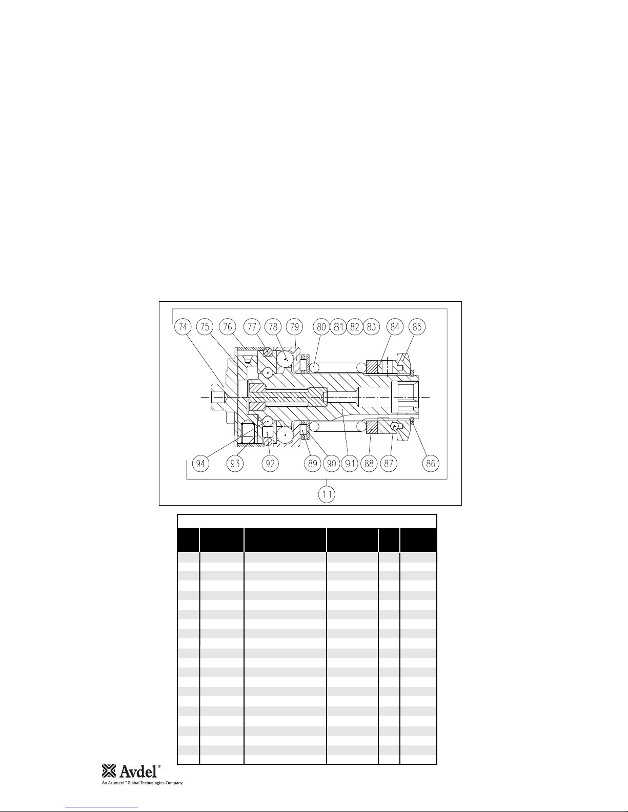
Clutch Assembly
Maintenance
CLUTCH ASSEMBLY PARTS LIST
TEXTRON
PART No.
SUPPLIER
PART No.
REC
SPARES
ITEM DESCRIPTION QTY
11 2050297023 CLUTCH ASS 84100-12011 1
74 296693 CAM CLUTCH 84100-12074 1
75 296623 LATCH PIN 84100-12075 1
76 296683 RETAINING SLEEVE 84100-12076 1
77 37233 O RING 84100-12077 1
78 81243 BALL 84100-12078 6
79 296673 CUP BALL 84100-12079 1
80
81 68448 CLUTCH SPRING - -GREEN 84100-15001 1
82 67428 CLUTCH SPRING - RED 84100-15011 1
83 71378 CLUTCH SPRING - YELLOW 84100-15021 1
84 76013 LOCKWASHER 84100-12084 1
85 76003 ADJUSTING RING 84100-12085 1
86 218453 CIRCLIP 84100-12086 1
87 72228 BALL 5mm 84100-12087 3
88 389833 THRUST WASHER 84100-12088 1
89 297963 THRUST RACE 84100-12089 1
90 297973 THRUST WASHER 84100-12090 1
91 296983 SPINDLE CLUTCH S.A. 84100-12091 1
92 18243 ROLLER 84100-12092 1
93 307123 SPRING 84100-12093 1
94 72408 BALL 1/8 84100-12094 14
DISMANTLING
Item numbers in Bold refer to illustration.
•Place Control Top 36 in vice using flats supplied. Unscrew Clutch Case 10 (L/H thread ).
•Remove Bit Holder 45 and Spring Washers 2-6.
•Remove Clutch Assy 11.
•Using the supplied Clutch Key rotate Adjusting Ring 85 till a minimum gap between 85 and Circlip 86 is obtained.
•Using suitable Circlip Pliers remove 86.
•Remove Adjusting Ring 85, and Items 84,87,88.
•Remove Clutch Spring 80, 81,82 or 83.
•Assemble in reverse order, ensuring that Clutch Case 10 is tightened to the correct Torque (6.8Nm) as shown on assembly
drawing 74100-12000 (S).

15
Maintenance
TO RESET CLUTCH TORQUE
•Ensure the correct coloured Clutch Spring is selected in order to obtain the required torque.
•With a minimum gap set between Adjusting Ring 85 and Circlip 86 and using the Clutch Key, rotate 85 (anti clockwise)
until the required number of full turns have been completed to obtain the required Torque as shown in the Table below.
•White numbers on black background indicate Number of turns. Black numbers on white background indicate expected
Torque in 1bf ins.
74100 CLUTCH DETAILS
SPRING
PART Nº
SPRING
COLOUR
1234567891011121314
Nº OF TURNS/lb f ins
UNSET CLUTCH
PART Nº
84100-15000 84100-15001 GREEN
84100-15010 84100-15011 RED
84100-15020 84100-15021 YELLOW
UNSET CLUTCH
PART Nº
SPRING
PART Nº
SPRING
COLOUR
Nº OF TURNS/lb f ins
19 21 22 24 26 29 - - - - - - - -
10 11 12 13 14 15 16 17 18 19 20 21 - -
16 17 18 19 20 21 22 23 24 25 26 27 28 29
245788899 - - - - -
ADJUSTING RING 85
CIRCLIP 86
CLUTCH SPRING
16
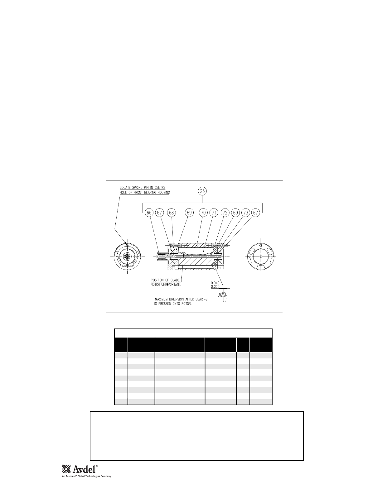
Motor Assembly
Maintenance
Item numbers in Bold refer to illustration.
•Assemble Plate Bearing 69 over rear spigot of Rotor 72, applying pressure to inner race of Bearing 67 press on to give
gap as shown.
•Assemble Blades 71 (5 off) to Rotor and slide Cylinder 70 over assembly.
•Fit Plate Bearing 69 over front spigot of 72. Supporting rear spigot of 72 apply pressure to inner race of 67, press on to
front spigot of 72.
•Fit Housing-Front Bearing 68 and Housing -Rear Bearing 73 to assembly.
Dismantle in reverse order.
MOTOR ASSEMBLY PARTS LIST
TEXTRON
PART No.
SUPPLIER
PART No.
REC
SPARES
ITEM DESCRIPTION QTY
26 313413 MOTOR ASSEMBLY 84100-12026 1
66 306543 PINION – 14T 84100-12066 1
67 33433 BEARING 84100-12067 2
68 304673 HOUSING-FRONT BEARING 84100-12068 1
69 254873 PLATE BEARING 84100-12069 2
70 254853 CYLINDER 84100-12070 1
71 300623 BLADE - ROTOR 84100-12071 5
72 306523 ROTOR – 8 SPLINE 84100-12072 1
73 254883 HOUSING - REAR BEARING 84100-12073 1
WARNING
WHEN ASSEMBLING OR SERVICING OIL FREE MOTOR SMOKING IS PROHIBITED. THE
ROTOR BLADES CONTAIN P.T.F.E. AND AT TEMPERATURES ABOVE 300° INHALING THE
RESULTANT VAPOUR MAY CAUSE A TEMPORARY ALLERGIC REACTION. CARE SHOULD BE
TAKEN WHEN BLOWING OUT P.T.F.E. RESIDUE FROM SINTERED SILENCER. ALWAYS WASH
HANDS BEFORE TOUCHING CIGARETTES, PIPES, FOOD ETC.

17
Gearbox Assembly
Maintenance
Item numbers in Bold refer to illustration.
•Thoroughly clean all components.
•Assemble Bearing 15 and Collar 14 onto Carrier Assembly 17, retain with Circlip 13.
•Apply recommended grease to all components and assemble into Gear Ring 20. Place Front Bearing Housing 16 over 15
and with Key 23 in place, slide into Motor Case 25. Tighten 16 to stated torque value.
GEARBOX PARTS LIST
TEXTRON
PART No.
SUPPLIER
PART No.
REC
SPARES
ITEM DESCRIPTION QTY
13 2050042353 CIRCLIP 84100-12013 1
14 2050306813 COLLAR (D) 84100-12014 1
15 2050251983 BALL BEARING 84100-12015 1
17 306723 CARRIER ASSEMBLY 84100-12017 1
18 299073 WHEEL PLANET 84100-12018 3
19 298893 BEARING CAGED NEEDLE 84100-12019 6
20 306823 GEAR RING 84100-12020 1
21 306993 CARRIER ASSEMBLY 84100-12021 1
22 299093 WHEEL PLANET 84100-12022 3
23 312553 KEY 84100-12023 1
20 23
1713 14 19 18 19 22
21
15

18
Setting the Push Rod
Maintenance
•Connect the tool to the air line so that the Valve Seat (A) is seated.
•Measure the protrusion of Push Rod (B)
•Obtain the specified dimension by grinding the Push Rod.
BA

19
Notes
20
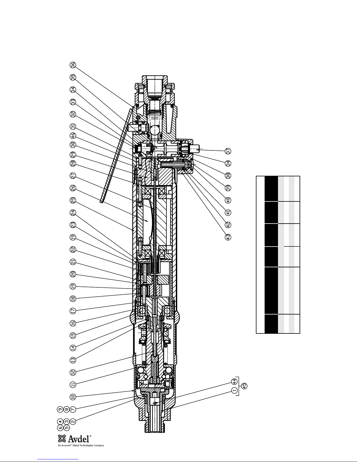
General Assembly of Base Tool 74100-12000
TIGHTENING TORQUES
lbf-ftNm. DIRECTION
OF HEAD
REF No. DESCRIPTION A/F
INT'L
HEX
36 TO 25 CONTROL TOP HAND TIGHTEN TO DATUM 32 L/H
16 TO 25 FRONT BEARING HS'G 40 29.5 19.3 L/H
10 TO 16 CLUTCH CASE COMPLETE 6.8 5 32 L/H
40 TO 29 VALVE BODY SCREW 3.1 2.3 - R/H
Other manuals for 74100
1
Table of contents
Other Avdel Power Tools manuals

Avdel
Avdel 71404 User manual

Avdel
Avdel Genesis G2LB User manual

Avdel
Avdel 7340 User manual

Avdel
Avdel 73432-02000 User manual

Avdel
Avdel 7271 User manual

Avdel
Avdel 74201 User manual

Avdel
Avdel TX2000 User manual

Avdel
Avdel GenesisG2-s User manual

Avdel
Avdel Genesis G2LB User manual

Avdel
Avdel eRiv User manual

Avdel
Avdel 74200 User manual

Avdel
Avdel Genesis G3 User manual

Avdel
Avdel 74101 User manual

Avdel
Avdel TX2000 User manual

Avdel
Avdel 07281 User manual

Avdel
Avdel Avbolt 07220 User manual

Avdel
Avdel 7412 User manual

Avdel
Avdel 73200 Tool User manual

Avdel
Avdel genesis g2 User manual

Avdel
Avdel Genesis G2LB User manual


