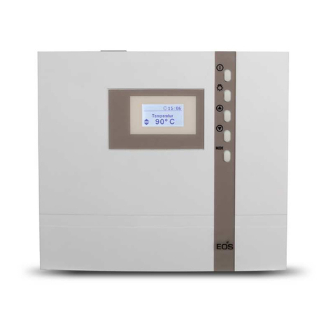
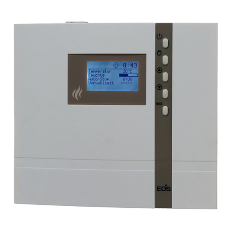
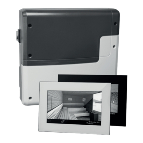
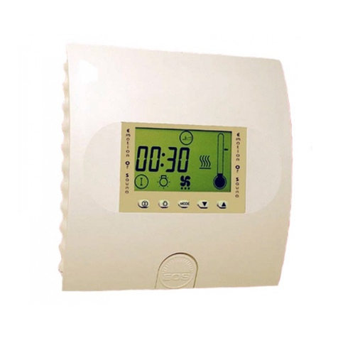
EOS ECON S2 User manual

INNOVATIVE SAUNA TECH N O L OGY
IP x4
Made in Germany
ECON S2
EN Installation and operating manual
control unit for steam generator
SteamRock Basic
print 29344783 en / 08.18
Technical changes reserved
Firmware < R4.31

2EN
ENGLISH
Contents
Scope of delivery ..........................................................................................................................................4
Specifications..................................................................................................................................................5
General information about steam rooms.............................................................................................6
General safety advices.................................................................................................................................7
Installation.......................................................................................................................................................9
Surface-mounting installation ...........................................................................................................9
Semi-recessed installation................................................................................................................ 10
Sensor connection............................................................................................................................... 11
Electrical connections............................................................................................................................... 12
Steam generator connection........................................................................................................... 12
Light connection .................................................................................................................................. 12
Fan connection ..................................................................................................................................... 12
Dosing pump connection................................................................................................................. 12
Installation diagram ............................................................................................................................ 13
Terminal layout ..................................................................................................................................... 13
Connection example for Econ S2 and SteamRock Basic........................................................ 14
Heating time limitation............................................................................................................................ 15
Protection fuses in the control unit..................................................................................................... 15
Operation...................................................................................................................................................... 16
General..................................................................................................................................................... 16
User interface .................................................................................................................................. 16
Operation buttons......................................................................................................................... 16
Basic display in„stand by“........................................................................................................... 17
Basic display during operation.................................................................................................. 17
Screensaver mode ......................................................................................................................... 17
Cabin lighting.................................................................................................................................. 18
First switching / commissioning............................................................................................... 19
Navigation language selection................................................................................................. 20
Time setting ..................................................................................................................................... 20
Enabling / disabling child lock .................................................................................................. 21
Switching the heating on............................................................................................................ 22
Switching the heating off............................................................................................................ 22
Personal settings .................................................................................................................................. 24
Temperature adjustment ............................................................................................................ 24
Essence dosing control................................................................................................................ 24
Heating time setting (auto-stop).............................................................................................. 26

3
EN
Start time pre-selection / timer................................................................................................. 28
Enabling start time pre-selection............................................................................................. 29
Disabling start time pre-selection ........................................................................................... 29
Holiday home mode / holiday park mode........................................................................................ 32
Error messages......................................................................................................................................33-34
“Switch-off” unit switch............................................................................................................................ 35
Service address ........................................................................................................................................... 36
General Terms and Conditions of Service.......................................................................................... 37

4EN
Delivery scope
Please verify that you have got all components which belong to the standard delivery.
1. Contol unit Econ S2
2. Temperature sensor Ø15 x 65 mm including separate 5 m connection cable
3. 3 mounting screws 4 x 25 mm.
4. 5 rubber grommets for connection cables
5. Installation and operation manual
(changes reserved)
1
4
b
235
a
Optional accessories:
Button for manual essence dosing......................item no. 94.6507
Essence dosing pump with accessories.............item no. 94.6297
5 l container for essences, with level probe......item no. 94.6298
Sensor cable 20 m......................................................item no. 94.6410
Sensor cable 50 m......................................................item no. 94.6411

5
EN
Specications
Power supply: 230 V 1 N AC 50 Hz
Switching capacity: 3 kW resistive load (AC1 operation) with 16 A protection
Heating time limitation: 6 h / 12 h / unlimited (via jumper setting)
Temperature control range: 30°C to 50°C
Temperature sensor: KTY type in metal housing Ø15 x 65 mm
Hysteresis: adjustable range 1K to 5K
Display: LCD display 65 x 37 mm, multi-line alphanumeric illuminat-
ed
Light control output: 230 V, max. 100 W load
Extractor fan output: 230 V, max. 100 W load
Essence dosing pump output: 230 V, max 100 W load
Protection class: IPx4 as per EN 60529 water splash proof
Housing: Plastic, for surface mounting or semi-recessed installation
Size (H x W x D): 220 x 250 x 67 mm (35 mm depth requirement by semi-re-
cessed installation)
Ambient temperature (operation): -10°C to +40°C
Ambient temperature (storage): -20°C bis +70°C
Applicable norms:
• 2014/35/EU
• 2014/30/EU
• DIN EN 60335-1
• DIN EN 60335-2-53
• DIN EN 60335-2-98
• DIN EN 60335-2-105
• DIN EN 62233
NOTICE
ONLY FOR USE WITH THE STEAM GENERATORS STEAMROCK BASIC.

6EN
Dear customer,
On purchasing this control unit, you have ac-
quired a high-quality device that was devel-
oped and manufactured in compliance with
the latest standards and quality guidelines.
Please note that perfect interaction of the
steam bath cabin, the steam generator and
control unit must be guaranteed to achieve the
typical pleasant steam bath atmosphere in your
cabin. This high-quality control unit is used to
'operate' your steam bath system; its many pro-
gramming options allow you to quickly nd the
settings that best suit your requirements.
Everybody experiences the climate in
the steam bath dierently, which is
why you need to nd your own indi-
vidual settings, or those of your family.
The following operation instructions de-
scribe how to pre-select "your" climate in
the cabin. Read these instructions careful-
ly, so that you can quickly and easily nd
your way though the programming process.
Please note that there are dierent tempera-
tures in the cabin of your steam bath.
Therefore there will always be temperature var-
iations between the control unit temperature
sensor and the thermometer in the cabin.
For instance, a pre-selected temperature of 50
°C may show a value of 38°C on your display
thermometer. This would then also correspond
to the typical climate data in the cabinet.
Only use suitable cabin lights. Always ensure
hygienic conditions.
To prevent draughts inside the cabin, try to
avoid using the fan function during your steam
bath. It should only be used if recommended
by the cabin manufacturer.
General information for steam baths

7
EN
• This device can be used by children aged
8 upwards and by persons with physical,
sensory, or mental disabilities, or persons
who have inadequate experience and
knowledge if they are supervised or if they
have received adequate instruction in how
to use the device safely and understand
the associated risks. Children may not play
with this device. Children may not clean
or carry out any user maintenance if un-
supervised.
• Children should be supervised to ensure
that they do not play with the device.
• Caution: The unit may not be in-
stalled in closed switch cabinets or behind
closed wooden panels!
• Only qualied electricians may install the
device.
• You must comply with the regulations of
your electrical supplier and applicable VDE
regulations (DIN VDE 0100).
• Caution, risk of fatal injuries: Nev-
er carry out repairs or installation work
yourself. Only a qualied technician may
remove the housing cover.
• Please always observe the dimensions
stated in the assembly instructions when
installing the temperature sensor. The
temperature limit values can only be ob-
served if the assembly work is carried out
correctly, and there is a very low tempera-
ture uctuation in the steam cabin.
• The unit may only be used as intended as
a control unit for steam generators up to
9 kW. Control units where there is the op-
tion of increasing the switching capacity
in combination with a power switching
unit can be used up to 36 kW.
• The system must be completely discon-
nected from the mains supply before car-
rying out any installation work or repairs,
i.e. switch o fuses and master switch.
• Observe the safety and installation infor-
mation provided by the manufacturer of
the unit.
• Please also observe the information and
instructions provided by the cabin manu-
facturer.
General Safety Regulations

8EN
!
Caution!
Dear Customer, In compliance with the
current regulations, only a qualied
electrician may connect the electrical
elements of the steam generator or the
steam bath control unit.
We would like to remind you that, in case
of a warranty claim, you will need to pro-
vide a copy of the authorised electronics
company's invoice.
!
Attention!
Make sure to use only the original spare
parts.
The extension of the cables included in
the delivery can cause malfunctions is
therefore not allowed.
Any unauthorized technical modication
voids the product warranty.

9
EN
Mounting holes
Installation of the control unit
Installation location
The control unit may be only mounted outside
steam room on a suitable wall surface.
Please follow the instructions for installation:
Fig. 2Fig. 1
Fig. 3
Eye level
Fig. 3.2
3 mm
Fig. 3.1
17 cm
17,7 cm
Eye level
Fig. 4
Feed-through for:
Mains cable
Evaporator cable
Lamp
Fan
Feed-through for:
sensor lines
Upper mounting hole
1. The 3 mm diameter boreholes for the sup-
plied wood screws 4 x 25 mm to be drilled
according to the dimensions shown in Fig. 3
+ 3.1.
2. Insert one of the wood screws into the top
center hole. The control unit is hooked onto
this screw. Therefore, leave the screw out by
approx. 3 mm (Fig. 3.2).
3. Hook the control unit onto the 3 mm pro-
truding screw in the upper mounting hole.
Insert the supplied rubber grommets into
the openings at the rear wall of the housing
and insert the connecting cable through
these openings.
Remove the control device cover. In order to do
this loosen the screw at the top of the housing
and pull the housing top upward while swivel-
ling (Fig. 1).
Surface-mounted installation
Fasten the housing bottom at the two bot-
tom openings (Fig. 4) rmly to the cabin wall.

10 EN
Fig. 6
21 cm
20 cm
Eye level
Holes to fasten the
control unit inside
the wall opening.
Fig.5
Recessed installation
1. Cut out a wall section that is at least 3.5 cm
deep according to the dimension in Fig. 5.
Insert the supplied rubber grommets into the
openings at the rear wall of the housing and
insert the connecting cables through these
openings.
Place the control unit into the wall opening and
fasten it with 4 wood screws.
Feed-through for:
Mains cable
Evaporator cable
Lamp
Fan
Feed-through for:
sensor lines

11
EN
ca. 160 - 170 cm
ca. 160 - 170 cm
min. 3 cm
30 mm
Temperature sensor installation
Do not install sensor and power supply lines together, or lead them through the same duct. Install-
ing these together may lead to malfunctions in the electronics, e.g. error messages.
Any cable shielding (if any) must be connected to the earth in the control unit.
Please note that the following information about sensor position provides only a guideline for
the optimal climate and temperature regulation in a standard cabin. Sensor position may vary
depending on the cabin situation. Fig. 8-10 provide an overview of the sensor installation.
Fig. 8
Sensor position
sensor housing
cable line
Fig. 9
Sensor installation:
tiles / mosaic
adhesive
vapour barrier
insulation
wall framework
silicone sealing
Fig. 10
sensor cable
Optimal position is normally
opposite to the steam out-
let with approx 2 m gap at
some 16-170 cm from the
oor level.
Notice: a too small or too
large gap may lead to incor-
rect temperature control.
Depending on the cabin
situation individual testing
may be required.
Make sure that the sensor
sticks to 30 mm out of the
cabin wall as per g. 10.

12 EN
Electrical connections
In general, there may be only one xed connec-
tion to the power supply. Equipment should be
provided that makes it possible to disconnect
the system with all poles from the power sup-
ply with at least 3 mm contact opening.
All electrical installations and all connection
lines that are installed inside the cabin must
be suitable for an ambient temperature and
should have the adequate humidity protection
class.
The power supply line should be drawn to the
control unit and connected to the connection
terminals as per wiring diagram.
The steam generator should be mounted out-
side steam room as per installation instruction
of the manufacturer / supplier.
Draw the connecting cable and make electrical
connections as per wiring diagram.
Make sure to observe specic connection
details as per wiring diagram for steam gen-
erator and control unit.
The general connections overview is shown
on page 13.
Steam generator connection
Cabin light connection
Heating time limitation
The heating time may limited with the jumper
5 on the main board to max. 6 hours, 12 hours
or it may be set to unlimited time.
By jumper setting „unlimited“ the heating
should be switched o manually.
Default setting from factory is “6 hours”.
!This setting is only allowed if the control
unit is switched o from power supply. Do not
set the jumper by working control unit!
Connect the cabin lamp as per wiring diagram.
!The lamp should have at least IPX6 pro-
tection class and should be suitable to the
steam room temperature range.
The lamp may be mounted at any place except
within the direct range of the steam ow com-
ing out or rising from the steam outlet.
Extractor fan connection
Dosing pump connection
Connect the fan as per wiring diagram.
The extractor fan should have at least IPx6 pro-
tection class. The fan should not be mounted
inside the steam cabin.
Recommended position of the fan is in the
duct channel for air extraction leading from
the cabin.
Notice: The position of the duct vent may have
an inuence on the temperature regulation if
the fan is operated during steam production.
Connect the dosing pump as per wiring dia-
gram shown on pages 13 and 14.
Make sure to observe the maximum allowed
power of the dosing pump.
Pay especial attention to the correct installa-
tion and connection of the dosing line to the
steam pipe.
!Attention!
Do not attempt to install or repair the unit
by yourselves. The unit’s housing may be
opened only by authorized and appropri-
ately qualied electrician. Danger to life!
!Attention!
The electrical connection may be carried
out only by a qualied electrician with
respect to the applicable local norms and
VDE regulations. Danger to life!

13
EN
Main board overview
Connections overview
36
2
3
3
5
230 V 1 N AC 50 Hz
ECON
400 V 3 N AC 50 Hz
3 3
optional
2
M
SteamRock Basic
X2
F2
F1
JP5
L N S1
WB
FR N
ST1
N
N LL N
ST2
ST2
sensor connector
Jumper JP5 for hea-
ting time limitation
F1 fuse
F2 fuse, rear
side of board
connector for re-
mote essence dos-
ing control switch
6 Std 12 Std unendlich
6 R12 246 R12 24 6 R12 24
!Use the N terminals only for light and fan connection!

14 EN
FR
WB
S1NL N
X2
Fragrance
PE
N L
ST1
N
ST2
L N
NL
M
N
PE
(Gr)
S1
Wb
ST1 A2
Ub
E
G
KTY
KTY
optional
ST2
ECON S2 connection to SteamRock Basic steam generator
SteamRock Basic
remote switch for
essence dosing
ECON S2
essence container
with level probe
230 V AC 50 Hz
essence
dosing pump
light fan
!
W
arning:
Always connect the neutral terminal (N) of the steam generator
SteamRock Basic. Incor-
rect connection can cause re and damages to persons.

15
EN
MAINS
L N S1
WB
FR
N
OVENLSG
N LN L
ST1
N
ST2
Heating time limitation
The heating time limitation can be adjusted with the JP5 jumper position on the main board of
the control unit. You can set the limitation to 6 hours, 12 hours or set the heating time to unlimited
(manual) mode. The JP5 jumper is located in the middle at the upper edge of the board. You will
need tweezers or an alike tool to change the jumper position. Alternatively you can also take the
board out of the housing slightly (undo the mounting screws in the corners).
If set to unlimited position („24“) with the heating time can be progrmmed up to 23:59 or also set
to„--:--“ position. The setting“--:--”means unlimited heating time. In such case the heating will
not stop automatically and needs to be stopped manually.
Power relay board S2
Devices‘ fuses
F1 = T 2A H 250 V Primary fuse protection for main electronics, light and fan.
F2 = T 315 mA L 250 V Secondary protection for main electronics.
!This setting may be carried out only by a skilled person. By all works on an open con-
trol unit disconnect the power supply on all phases. Do not change the jumper position
without disconnecting the power. Risk of electric shock! Risk of damages to the unit!
Jumper JP5 for heating time limitation
X2
F2
F1
JP5
L N S1
WB
FR N
ST1
N
N LL N
ST2
ST2
Mounting screws
Control board
F1
F2
6 h
12 h
unlimited
6 R12 24
6 R12 24
6 R12 24
Limitation up to 6 hours hea-
ting time (factory default)
Limitation up to 12 hours hea-
ting time
Unlimited heating time - no
automatic switch o if the „Au-
to-Stop“ parameter has been
set to „--:--“.

16 EN
Operation
General Details
Once the control unit has been installed with all components and all covers have been xed, you
can put your sauna unit into operation.
The following pages provide the detailed explanation, how to operate your control panel and
make all necessary settings.
Operation elements
Operating buttons
= Cabin lighting on/o
= Heating on / o (stand-by)
= Programming mode (settings)
= Reduce value / next function
= Increase value / next function
MODE
MODE
LCD-Display
operating buttons

17
EN
control unit locked (hotel mode)
pre-set timer active
Holiday home mode
Holiday park mode (if ashing)
Descaling pending (symbol ashes)
Descaling in progress (symbol ashes)
12:34
30°C
30°C
is shown if the control unit is in stand-by model
The display will automatically switch this in-
terface from any state if no button has been
pressed within >15 sec.
Interface in stand by
Interface during active heating
is shown if the control unit is in active operation
mode (heating is switched on).
The display will automatically switch this in-
terface from any state if no button has been
pressed within >15 sec (during active heating).
Heating process indication:
During the heating-up phase the bars behind
the temperature gures will ll progressively.
Once the pre-set temperature has been
reached, the bars will remain lled.
Interface in energy-saving mode
current time
the clock symbol
the light symbol
(appears if the light is on)
12 : 00
In addition, the following symbols are displayed
depending on the selected operating mode
.
If the control unit is not used for a longer time it
will switch into the energy-saving mode.
A clock randomly moving across the display
every minute will be shown after 5 minutes,
similar to a PC screensaver. The backlighting of
the display is switched o after an additional 15
minutes
By pressing any key you can wake the unit to
the default “Stand-by” interface.
The following symbols are displayed
at the top of the control unit:
12:00
Temperature 30°C
Fragrance 30
Auto-Stop 5:59
Start time - - : - -
12:00
Temperature 30°C
Fragrance 10
Auto-Stop 6:00
Start time - - : - -

18 EN
12:00
Temperature 30°C
Fragrance 30
Auto-Stop 6:00
Start time - - : - -
12:00
Temperature 30°C
Fragrance 30
Auto-Stop 6:00
Start time - - : - -
12:00
Temperature 30°C
Fragrance 30
Auto-Stop 6:00
Start time - - : - -
12:00
Temperature 30°C
Fragrance 30
Auto-Stop 6:00
Start time - - : - -
value to be adjusted
paramter to be adjusted
highlighted paramter
Temperature
In order to adjust the individual values to the
particular preference, briey press the MODE
-button out of Stand-by.
The rst parameter will then be highlighted in
inverted colour. and You can then select the de-
sired parameter with the or - buttons.
By pressing the MODE button again you will
launch the programming mode.
The value of the parameter will ash and will be
shown inverted.
Use the or buttons to change the value
of the selected parameter.
To save the changed value press MODE for over
3 seconds. Once saved the value stops ashing.
The new value will be applied immediately un-
til another change is made.
If no button is pressed for >15 seconds the unit
switches back to the default display. Changes
made up to then will not be saved
Cabin light
The cabin lighting is automatically switched
on as soon as the heating is switched on. In
the top left of the display the - symbol is
shown. When the heating is switched o the
cabin lighting will switch o with a delay of 30
minutes.
Irrespective of the status of the control unit, the
cabin lighting can be switched on or o any-
time with the light button .
Values that ash on the display can be changed
with the or - buttons and are shown in
these instructions as displayed.
12:00
Temperature 30°C
Fragrance 30
Auto-Stop 5:59
Start time - - : - -
12:00
Temperature 30°C
Fragrance 30
Auto-Stop 5:59
Start time - - : - -

19
EN
Initial commissioning
DE
GB
NL
PL
IT
RU
12:00
00:00
0: 00
Time of day
DE
GB
NL
PL
IT
RU
12:00
00:00
12 : 00
Time of day
00:00
12 : 00
Time of day
00:00
12 : 15
Time of day
> 3 Sec
Language selection
Time setting
> 3 Sec
MODE
MODE
MODE
Unit setup starts with language setting. You
can choose from 12 languages. Use up/down
button to select language, press “mode” for 3
sec to conrm.
Set the time of day.
First set hours. Use up/down button to select
value and press“mode” shortly to conrm.
Now set minutes. To conrm time setting
press “mode” for 3 sec.

20 EN
12:00
12:00
1
12:00
12:00
3
12:00
> 3 Sec
MODE
> 3 Sec
MODE
range 0 - 2
range 1 - 5 K
12:00
10
> 3 Sec
MODE
range 0-15 s
(default 0)
You can set the hysteresis from 1K to 5K in order
to adjust the temperature regulation and opti-
mize steam production.
Use “down” button to change value and press
“mode” button for 3 seconds to conrm.
Default value is 3K.
This setting adjusts the essence injection du-
ration and thus allows you to set the essence
quantity per each injection.
For instance the setting “10” means the dosing
pump will run for 10 seconds per injection.
You can make the setting from 1 to 15 sec.
After this the setup is complete and the
control unit will switch to the regular stand-by
interface.
Set the fan operation mode by selecting the
setting value from 0 to 2.
0 = fan disabled during heating, fan will run only af-
ter the heating (cabin dry cycle)
1 = fan is on during steam o intervals (active heat-
ing) + fan runs after heating (cabin dry program)
2 = fan is always on if heating is on, + fan runs after
heating (cabin dry cycle)
Press“mode” for 3 sec to conrm setting.
Fan setting
Hysteresis setting
Essence dosing setting
12:00
Temperature 30°C
Fragrance 30
Auto-Stop 6:00
Start time - - : - -
Table of contents
Other EOS Control Unit manuals
Popular Control Unit manuals by other brands

Trinamic
Trinamic PD-1160 Getting started

Dyna-Flo
Dyna-Flo 570 Operation, Parts, and Instruction Manual

GEM
GEM 613 Installation, operating and maintenance instructions

Elektrogas
Elektrogas VML Series Technical manual

Leadshine
Leadshine 2CS3E Series user manual

Hacker
Hacker UAV Control Opto Pro Series manual