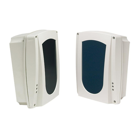
AVS Electronics BF100 R User manual

- 13 - IST0570V3.1
IST0570V3.1
BF100 RBF100 R
BF100 RBF100 R
BF100 R
Reflecting IR
smoke
barrier
Curtarolo (Padova) Italy
www.avselectronics.com
Product approved
according to
EN 54 - 12 standard
E
N
G
G208015
0786-CPD-20627
CERTIFIEDQUALITY
SYSTEM
UNI EN ISO 9001:2008

- 14 - IST0570V3.1
General Features
-Smokedetection systemmade ofan emitterand areceiver, whichthanks toa reflectingpanel
placed at max 100 meters distance, can detect and determine the quantity of smoke in the
protectedarea.
-The board is equipped with a view-finder, placed on one side, allowing a rough alignement
withthereflectorgivenwithin.
-The beam is equipped with a device (Led/display module) to use for calibration and check of
signalreceived.
-At first supplying, the board makes a self-calibration which will be repeated every 2 hours in
ordertocompensatemaskingcausedbydust onlenses andreflector.
-Adjustablesensitivity toget abetter interventionthreshold accordingto distance.
-Thebeamhasalarmoutputsaswellasfaultconditionandconsumption-alarmoutputs, which
allowconnection tostandard firecontrolunits.
-Thebeamhas aserialinterface in orderto connect upto 4 unitsto the remotepanel (BR100)
showingthesameindicationsasshownbyled/displaymoduleandleds.
S8
OUT
+FALLARME NONO GUASTO
C
NC C
NC
S4S3
S6
3
1
2
5
4
4321
ON S1
S2
S7
LD3
LD4
LD2
+-BA
S5
8
7
6
S9
E
N
G

- 15 - IST0570V3.1
LED/DISPLAY
MODULE BF TEST
ELECTRONIC
BOARD
COVER
BR100(OPTIONAL)
REFLECTING
PANEL
E
N
G

- 16 - IST0570V3.1
Terminal Board
A
-BC
GUASTOALLARME
S7
NC C
NO NC
NO
S8
OUT
+F +
S6
Theterminal boardismadeof
two separate groups: the one
ontheleft concernsalarmand
fault-conditionoutputwhilstthe
one on the right concerns
supplyinginputandserialdoor.
ON/CN MRALA .yalerMRALAfoegnahcxE .detcetedneebsahekomsretfasdnoces04tuobaevitcasitI .ON/CroCN/Cegnahcxeehttesotredroni7SrepmujnotcA
ON/CN TLUAF NOITIDNOC
.yalerTLUAFfoegnahcxE langisehtfopordneddusfonoitcetedretfaetunimenotuobaevitcasitI ehtetasnepmoctonseodnoitarbilac-flesnehwrolevelmuminimrednu .pordlangis .ON/CroCN/Cegnahcxeehttesot8SrepmujnotcA
C
F+TUO fonoitcennoctceridehtswollatuptuosihT.yalermralaehtsasetavitcatI ehtmralagniruD.tinulortnoceriflanoitnevnocfoenilenootmaebeht .mho086siegrahcecnetsiser
+)V8,72xam/V5,11.nim(V42roV21evitisopgniylppuS
-evitagengniylppuS
A001RBeludomlanoitpootnoitcennocrofroodlaireS
B
Signalling Led
Moduleto visualizethesignal:
–duringnormalworking,displayvisualizesthesignalvaluewhilstLedsbar
visualizesthe percentageof masking.
–duringalarm conditionthe letterA isvisualized.
–duringfault conditionthe letterF isvisualized.
-duringcalibrationthe displayvisualizestheunitvalueswhilsttheLedsbar
visualizesthe decimalvalues ofsignal received.
Modulefor visualizationof detectorcondition:
EDOMNOITARBILAC
DER 2DL FFO
NEERG 3DL NO
WOLLEY 4DL FFO gnihsalF noitarbilaccitamotuA )NOni3piD(noitarbilaclaunaM
EDOMLAMRON
DER 2DL FFONO noitidnoclamroN mralA
NEERG 3DL gnihsalfwolS gnihsalfkciuQ )sdnoces2yreve(noitidnoclamroN dlohserhtmralaehtgnideecxeekomshtiW
WOLLEY 4DL FFO gnihsalfkciuQNO
noitidnoclamroN mrala-erpnoitidnoctluaf(muminimrednulevellangiS )
noitavitcayalertluaffoemitemasehttA
S7 S8
1 2 3 4
S2 S3 S4
ON S1
LD3
LD4
2
3
4
5
6
7
8
LD2
1
E
N
G

- 17 - IST0570V3.1
Jumper
Dip switch
1levelytivitisnesfognitteS
2levelytivitisnesfognitteS
3FFO NO gnikrowlamronfoedoM gnikrownoitarbilacfoedoM
4desutoN
ON
1 2 3 4
S1
S7 S8
S2 S3
S9
S4
S6
S5
ON
1 2 3
S1
4
E
N
G
1S )repmuj-eriW( ylnoesuyrotcaf,tuctonoD
2S 001RBeludometomerhtiweugolaidrofnoitcelessserddA
3S 001RBeludometomerhtiweugolaidrofnoitcelessserddA
4S 001RBeludometomerhtiweugolaidrofnoitcelessserddA
5S rotaunettA )repmuj-eriW( desolC nepO rotcelferdnamaebneewteb.tm001ot53morfecnatsidroF rotcelferdnamaebneewteb.tm53ot5morfecnatsidroF
6S gniylppuS )repmuj-eriW( desolC nepO gniylppusV21 gniylppusV42
7S yalerMRALA tcatnocCN:2-1noitisopnI tcatnocON:3-2noitisopnI
8S yalerTLUAF tcatnocON:2-1noitisopnI tcatnocCN:3-2noitisopnI
9S MRALA TESER
desolC
nepO
lortnoceriflanoitnevnocafoenilehtotdetcennocF+tuptuofiylnO gnillangismralarofdesusitinu sedomnoitcennocrehtollanI

- 18 - IST0570V3.1
H
1/2D 1/2 DD D
TX/
RX
TX/
RX TX/
RX
D
D
1/2 D
1 mt
TX/
RX
TX/
RX
TX/
RX
1/2 D D
TX/
RX TX/
RX
Installation Rules
Thebeam andthereflector mustbeinstalledonplane wall,notsubject tovibrationsordeformation.
Please keep in mind these basic rules:
-distance between the beams (D)
must be between min 10 and
max. 18 meters.
-distance from the walls
mustbeabout the half of
the distance between
two beams (1/2 D).
-distance from the ceiling
(H)mustbebetweenmin.40
cm. and max 1 meter.
-check the possibility of installing
reflectorsinaxiswithbeams.
Incase ofinclinationoftheroof, installthefirstbeamat about1 meter
fromthehighestwalland atHdistance fromthe ceiling.
Installother beamsmaintaining distanceD between
themanddistance Hfromthe ceiling.
Check to have max 1/2 D distance
between the beam and the lowest
sideofthewallfrom theceiling.
Check the possibility of
installingreflectorsinaxiswith
beams.
In case of sloping roofs, install the first beam at H
distancefromthehighestside ofthe roof.
Install other beams maintaining distance D
betweenthem anddistanceHfrom theceiling.
Check to have the max distance of 1/2D
betweenthebeam andthe wall fromthe
lowestsideoftheroof.
Check the possibility of installing
reflectorsinaxiswithbeams.
H
E
N
G

- 19 - IST0570V3.1
Installreflector maintainingit inaxiswiththebeam.
Fordistancebetween5 and70metersuseonlythereflectingpanelyoufind
withinthebeam inorder tohave areflectingsurface of20 x20cm.
Fordistance between70 and100 meters,addKit BFS (3reflectingpanels)
tothe panelgiven withinthe beam inorder toobtain areflectingpanelof40
x40cm.
Inthis case,panels musthave allfixing holesin thesamedirection.
Installthe beam maintainingit inaxis withthereflector.
Installation
MAX 10°
MIN 5 MT
MAX 100 MT
Forcorrectworking,eitherthebeam andthereflectormust
be on the same axis. Max tolerance is about 10° in both
verticaland horizontalposition.
Exceedingthis, thebeam will notwork properly.
Pointingholes
Fixingholes
InsertsmallmirrorBF TEST (this
accessory is necessary for a
correctadjusting) inrightpositionas
shownonsidepicture,maintainingthe
pointinghole upwards.
For installation onto the wall either reflector and
beam need flat cylindrical-head screws.
E
N
G

- 20 - IST0570V3.1
Working mode “Calibration”
VERTICAL
ADJUSTER HORIZONTAL
ADJUSTER
REFLECTOR
DX
SX
UP
-In order to make a first rough alignement, use
optical view-finder, visualizing the centre of the
concernedreflectorinthecentreoftheframed
area. In order to move orientation towards
right, rotate the horizontal adjuster
clockwise, in order to move orientation
towards left, rotate the horizontal
adjuster counter-clockwise.
To move orientation upwards rotate
the vertical adjuster counter-
clockwise, to move it
downwards rotate the
adjuster clockwise.
-Before supplying the beam
check jumper S6 condition:
•keep it closed for 12V
supplying
•cut it for 24 V
-SetS5accordingtodistancebetweenbeam
andreflector:
•cutjumperfor distancefrom5 to 35 meters.
•keep jumper closed for distance from 35 to 100 meters.
-Atfirssupplying, thebeamis blockedfor about30seconds. Waitbeforefollowing step
-MoveDIP3in ONto havethe beamin“Calibration”mode:
•yellowLed willflash andfaultrelaywillbe activated.
•Led/displaymodule willvisualize thevalue ofsignalreceived.
-Actagainontheadjustersinordertoobtain maxsignalvaluevisualizedbyLed/displaymodule.
-Minimum signal is 2 (display) and 5 (Led).
-Oncereachedthebestsignal,moveDIP3againinOFFposition(NORMALworking),checking
that there are no obstacles between beam and reflector.
-Afterfewseconds,thefaultrelayisdeactivatedandyellowLedwillbe off.
-We suggest you to take note of the signal shown on display in order to compare it to the
values which will be read during future maintenances.
Thisis inorder tocheck whetherthe beamvisualizes alower valueon display,with calibration
atregularintervals.
Ifthis occurs,it willmean thatit isnecessary toremove dustand dirty.
Lower value,
invert
adjusting
direction
toincreasesignal
Initialvalue,rotate
the
adjusters
to
optimizethesignal
Continue until
reaching
the max
possible signal
VALUEATFIRSTCALIBRATION DISPLAY ........... LED .............
6
1
4
2
3
5
8
7
6
1
4
2
3
5
8
7
1
4
3
2
5
6
8
7
1
3
2
6
5
4
7
8
E
N
G

- 21 - IST0570V3.1
-Consideringthatthelongeristheprotectedrange,the longeristhe beamconcernedbysmoke,
itwould bebetter tosetthesensitivitylevelaccordingto distancebetween beamand reflector,
followingindications shownin thechartbelow.
Once calibration is made, take off the adjusting mirror BF TEST before closing with
cover.
The4 fixingholes onthe covercanbe“hidden”usingthescrew-covers givenwithin.
Working Mode “Normal”
HerearetheindicationsgivenbythethreeLedsontheleft:
–during normal working: greenLed flashesaboutevery2seconds,redLedisoff,yellowLed
isoff.
–during alarm: as soon as the beam detects presence of smoke, green Led will flash quickly,
redLedandyellowLedwillbeoff.Afterabout40secondsiftheeventcausingthealarmcontinues,
green Led will keep on flashing quickly, red Led will be on and alarm relay will be activated,
yellowLed willbe off.
Whenthe eventcausing thealarm isover, greenLed willstart againflashingevery2seconds,
redLedwillremainonandalarm relaywill remainactivated.
Thealarm signallingisreset:
–if the output +F connected to a conventional fire control unit (Jumper S9 closed) has
been used for the alarm signalling,theresetwillbe automaticresetting thecontrol unit.
–Forall otherconnection modes (JumperS9 opened),theresetis madetakingoffsupplying
frombarrierforfewseconds.
–Inanycase, if the module BR100 is used, resetcan alsobemade byuse ofthemechanical
key onboard.
–In case of fault condition: as soon as the beam detects a sudden drop of signal, green Led
willflash quickly,redLedwillbe off,yellowLedwillflash quickly.After about1minute,if thethe
eventcausingit persists,green Ledwill keeponflashing quickly,yellow Ledwillbefixon and
concernedrelay isactivated.
–Fault signalling is automatically reset as soon as the event stops. The beam is automatically
backin conditionof“normalworking”.
Byuseofremotemodule BR100following indicationswill beavailable:
DISPLAY
–during normal working: a value between 0 and 9 is visualized, corresponding to the signal
receivedduring lastcalibration (manualor automatic).
–in case of alarm: letterA isvisualized.
–in case of fault condition: letter Fis visualized.
LED BAR
–presence of a strong reflection: Led 7 or 8 on.
–during normal working: Led 5 or 6 on.
–in case of alarm or fault condition : one of the Leds under 5 on.
Ex.:ifLed 3is on,itshows thatthesignal islower than50%compared tothe best signal.
leveL foegatnecreP gniksam dnamaebneewtebecnatsiD rotcelfer 1PID 2PID
1 %52 sretem53ot5morF NO NO
2%03 sretem05ot01morF FFO NO
3 %04 sretem001ot03morF NO FFO
GNINRAW GNINRAW GNINRAW GNINRAW GNINRAW gnitteshctiws-pideht: FFO-FFO .desuebREVENtsum
E
N
G

- 22 - IST0570V3.1
LD3
LD4
LD2
4321
ON S1
S8
+F
OUT
NO
ALLARME
NO GUASTO
C
NC C
NC
S4S3
S6
S2
S7
+-BA
S5
LD3
LD4
LD2
4321
ON S1
S8
+F
OUT
NO
ALLARME
NO GUASTO
C
NC C
NC
S4S3
S6
S2
S7
+-BA
S5
LD3
LD4
LD2
4321
ON S1
S8
+F
OUT
NO
ALLARME
NO GUASTO
C
NC C
NC
S4S3
S6
S2
S7
+-BA
S5
LD3
LD4
LD2
4321
ON S1
S8
+F
OUT
NO
ALLARME
NO GUASTO
C
NC C
NC
S4S3
S6
S2
S7
+-BA
S5
BR100
Inordertoobtainsignalvisualizatioinin realtime, itis possibleto remotethe display/ledmodule of
anysinglebeam, locatingit inremotepanel BR100. Any BR100 remote panel can locate
upto4display/Ledmodules.
Dialogue between the remote panel and the beam occurs
thanks to a serial connection as shown on side drawing.
Connect A and B terminals of beam to concerned A and B
terminalson BR100remote panel.
BR100 supplying must be separate from beams
supplyingasapossible short-circuitinremote panel
supplying may cause a cut in beams supplying
(EN54-12 norm). To this purpose use 500 mA fuse
togetherwith itsfuse-holder givenwithinBR100panel.
Single beams connected to BR100 must be addressed using
Jumpers S2, S3 and S4 on board (see chapter JUMPER), in
thefollowingway: +-
REIRRAB 1 2 3 4
2S DESOLC NEPO NEPO NEPO
3S NEPO DESOLC NEPO NEPO
4S NEPO NEPO DESOLC NEPO
Supplying
Fuse
AB+-
noisnetlanimoN V8,72-5,11
noitpmusnoC Am011xam
esuF V052LA5.0F
TECHNICAL FEATURES
RESET: it makes a reset of alarm
condition.
NORMAL: during normal working of
beams.
TEST: it triggers off a total alarm of
allconnected beams.
BR100 Connection
E
N
G
1S :nepO :desolC gniylppusV42 gniylppusV21

- 23 - IST0570V3.1
ALLARME
NO
NC
+FGUASTO
C
NO
NC
COUT +-BA
R1
Connectionsto ControlUnits
BF100R beam is equipped with:
ALLARME
NO
NC
+F
GUASTO
C
NO
NC
COUT
R1
R2
Inbothcases,ifmodule BR100is used,reset canbe donethrough mechanicalkeyonboard.
-RelayALARM output.
Contactsofthisoutputcan beC/NC orC/NO
accordingtosettingofjumperS7(seechapter
JUMPER).
In order to reset the beam from alarm
condition,it isnecessarytotakeoff supplying
fromthebeam forafew seconds(JumperS9
open).
An example of connection using these contacts is
shownonside-drawingwhereALARMcontactisset
on C/NO and FAULT relay is set on C/NC.
R1 is the end-line resistence which is usually given
withincontrolunit.
R2 isthealarm resistence(for AVScontrol units
the value of this resistence is 680/1000 ohm –
3W)(not included).
-OUT+Ffordirectconnectionto AVS
conventionalfirecontrolunits(charge
of680 ohmduring alarm).
Inordertoreset thebeamfromalarm
condition, simply make a reset
operationoncontrol unit(Jumper S9
closed).
Side-drawing shows an example
of connection using these
contacts: R1 is the end-line
resistance usually given with
controlunit. FAULT contactis seton
C/NC.
E
N
G

- 24 - IST0570V3.1
AVS ELECTRONICS S.p.A. reserves the right to modify the technical and esthetical characteristic of the products at any time.
E
N
G
:rotcetedfoepyT rotcetedekomsmaeb-derarfnideslupdnadetaludom
egnaR sretem5.nim sretem001.xam
egarevoC xamsretem.qs008.1
noitarbilaC rabdeL/yalpsidfoesuyb
tiklanoitpO 001RB rabdel/yalpsidrofgnisuohetomer:
SFB sretem001ot07morfegnarrofslenapgnitcelfer3: TSETFB noitarbilacrofrorrimllams:
gniylppuS tloV8,72ot5,11morf
noitpmusnoC eludomV21htiwnoitidnocteiuq- Am25
eludomV21htiwnoitidnocmrala- Am07
eludomV42htiwnoitidnocteiuq- Am26
eludomV42htiwnoitidnocmrala- Am58
rabdeL/eludomyalpsid- Am51
:stuptuO yalermrala- V21taAm005
yalertluaf- V21taAm005
stinulortnoceriflanoitnevnocotnoitcennoctcerid- lenapetomerotnoitcennocrofroodlaires-
:erutarepmeT C°04+/C°5+
:eziS .mm112x951x69
:lavorppA 21-45NEINU
eergedPI 46PI
G208015
Power to this device must come from a SELV type power supply having characteristics of
currentlimitation andfuse protectedoutput. (ref.EN 60950)
INSTALLATION AND MAINTENANCE MUST BE EXECUTED BY QUALIFIED
PERSONNEL
TECHNICAL FEATURES
Via Valsugana, 63Via Valsugana, 63
Via Valsugana, 63
35010 (Padova) ITALY35010 (Padova) ITALY
35010 (Padova) ITALY
Tel. 049 9698 411 / Fax. 049 9698 407Tel. 049 9698 411 / Fax. 049 9698 407
Tel. 049 9698 411 / Fax. 049 9698 407
www.avselectronics.comwww.avselectronics.com
www.avselectronics.com
Productinconformity to89/106/CEE -
2004/108/EC Directives

- 25 - IST0570V3.1
IST0570V3.1
BF100 RBF100 R
BF100 RBF100 R
BF100 R
Détecteur
linéaire de fumée
à réflexion
Curtarolo (Padova) Italy
www.avselectronics.com
Produit homologué
UNI EN 54 - 12
F
R
A
G208015
0786-CPD-20627
SYSTÈMEDE QUALITÉ
CERTIFIÉ
UNI EN ISO 9001:2008

- 26 - IST0570V3.1
CARACTÉRISTIQUES GÉNÉRALES
-Système de détection composé par un ensemble Émetteur / Récepteur qui est capable de
détecter et déterminer la quantité de fumée présente dans un environnement, grâce à un
réflecteur(panneaucatadioptrique)placéàunedistance maximalede 100mètres.
-La carte est fournie avec un viseur optique, positionné sur un coté, qui permet d’effectuer
l’alignementde baseavec leréflecteur correspondant.
-Labarrière estdotée d’uninstrument interne(module led/écran), aveclequel laprocédure de
calibrationesteffectuée,ainsiquelecontrôledusignalreçu.
-Apartirde la1ère alimentation, lacarte effectueuneautocalibrationtoutesles 24heures, pour
compenserl’obscurcissementcrééparlapoussièrequisedéposesurleslentillesetleréflecteur.
-Ilestpossiblederéglerleniveaudesensibilité,enoptimisant leseuild’intervention, enfonction
deladistance detravail.
-La barrière possède les sorties d’alarme, de défaillance et d’alarme par consommation, qui
permettentde la connecteraux centralesanti-incendie standard.
-Labarrière possèdeuneinterface sériequisert pourconnecterjusqu’à4 barrièresaupanneau
distantdecontrôle (BR100),sur lequelsont indiquéeslesmêmes donnéesprésentées surla
barrière,grâceaumoduleled/écran etles ledd’information.
S8
OUT
+FALLARME NONO GUASTO
C
NC C
NC
S4S3
S6
3
1
2
5
4
4321
ON S1
S2
S7
LD3
LD4
LD2
+-BA
S5
8
7
6
S9
F
R
A

- 27 - IST0570V3.1
MODULE
LED/ÉCRAN BF TEST
CARTE
ÉLECTRONIQUE
COUVERCLE
BR100(OPTIONNEL)
PANNEAU
CATADIOPTRIQUE
F
R
A

- 28 - IST0570V3.1
Borne
A-B
C
GUASTOALLARME
S7
NC C
NO NC
NO
S8
OUT
+F +
S6
La borne est formée de 2
groupes séparés : ceux de
gaucheprésententles sorties
d’alarme et de défaut, celles
de droite incluent l’entrée
d’alimentationetle portsérie.
Led d’information Modulepour lavisualisation dusignal :
-Lorsdu fonctionnementnormal, l’écranindique lavaleur dusignal,alors
que la barre à led précise le pourcentage d’obscurcissement
-En état d’alarme, la lettre A apparait
-Enétatde défaillance, lalettre F apparait
-Pendantlacalibration, l’écranindique lesvaleursunitaires, alorsque la
barreàled indiqueles valeursdécimales dusignalreçu.
Modulepourla visualisationde l’état dela barrière:
NOITARBILACEDÉTILADOM
EGUOR 2DL tnietÉ
EGUOR 3DL émullA
ENUAJ 4DL tnietÉ tnatongilC euqitamotuanoitarbilaC )NOne3PID(elleunamnoitarbilaC
ELAMRONÉTILADOM
EGUOR 2DL tnietÉ émullA elamronenoizidnoC emrallA
EGUOR 3DL tneltnemetongilC edipar.metongilC )sednoces2seletuot(elamronnoitidnoC inifédérpemrala’dliueselessapédiuqeémufaledcevA
ENUAJ 4DL tnietÉ edipar.metongilC émullA
elamronnoitidnoC inifédérpliueselsuoslangiseduaeviN )ecna
lliafédemrala-érp( ecna
lliafédedialerudnoitavitca'làtneménatlumiS
S7 S8
1 2 3 4
S2 S3 S4
ON S1
LD3
LD4
2
3
4
5
6
7
8
LD2
1
ON/CN EMRALA
:ON-FNémreFtnemelamroN=CN(emrala'dialerudegnahcÉ aerèirrabaleuq.ces04sèrpaevitca'S)ONtrevuOtnemelamroN .eémufaledétcetéd tnemelamroN=CN(CN/Cegnahcé'lrelgérruop7SreilavacelrusrigA ON/Cuo)FNémreF
C
ON/CN -ALLIAFÉD ECN
ecnalliafédedegnahcÉ etuhceuqsurbenuétcetédtiaerèirrabaleuqsèrpaetunimenuevitca'S àsulptissuérenerèirrabaldnauquo,muminimliueselsuoslangised .noitarbilacotua'lraplangisedetuhcelresnepmoc tnemelamroN=CN(CN/Cegnahcé'lrelgérruop8SreilavacelrusrigA )trevuOtnemelamroN(ON/Cuo)FNémreF
C
F+TUO
retcennocedtemrepiuqeitroS.emrala'dialernuemmocevitca'S eidnecniitnaelartnecenu'dengilenuàerèirrabaltnemetcerid edecnatsiséredegrahcenuetnesérpelle,emralanE.ellennoitnevnoc .mho086
+)V8,72xam/V5,11.nim(V42oV21ednoitatnemila'dfitisoP
-noitatnemila'dfitagéN
A001RBlennoitpoeludomelcevanoixennocalruopeiréstroP
B
F
R
A

- 29 - IST0570V3.1
Cavaliers
Dip switch
1sétilibisnessedegalgéR
2sétilibisnessedegalgéR
3FFO NO "lamron"tnemennoitcnofedétiladoM "noitarbilac"tnemennoitcnofedétiladoM
4ésilitunoN
ON
1 2 3 4
S1
S7 S8
S2 S3
S9
S4
S6
S5
ON
1 2 3
S1
4
1S )lifàtnoP( enisu'degaratelruopésilitutnemeuqinu,repuocsapeN
2S 001RBtnatsideludomelcevaeugolaidelruopesserda'lennoitceléS
3S 001RBtnatsideludomelcevaeugolaidelruopesserda'lennoitceléS
4S 001RBtnatsideludomelcevaeugolaidelruopesserda'lennoitceléS
5S ruetaunéttA )lifàtnop(
émreF trevuO elteerèirrabalertnesertèm001à53edecnatsidenuruoP .ruetcelfér .ruetcelférelteerèirrabalertnesertèm53à5edecnatsidenuruoP
6S noitatnemilA )lifàtnop( émreF trevuO V21ànoitatnemilA V42ànoitatnemilA
7S ialeR EMRALA'd FNtcatnoc:2-1noitisopnE ONtcatnoc:3-2noitisopnE
8S edsialeR ecnalliaféd FNtcatnoc:2-1noitisopnE ONtcatnoc:3-2noitisopnE
9S -ILAITINIÉR NOITAS EMRALA
émreF
trevuO
noitacidni'lruopeésilitutseF+eitrosalistnemeuqinuresilituA -itnaellennoitnevnocelartnecenu'dengilalàeétcennocemrala'd nosiailedsétiladomsertuaselsetuotruoP.eidnecni
F
R
A

- 30 - IST0570V3.1
H
1/2D 1/2 DD D
TX/RX
TX/
RX TX/
RX
D
D
1/2 D
1 mt
TX/RX
TX/RX
TX/RX
1/2 D D
TX/RX TX/RX
Réglage d’installation
Labarrièreet leréflecteur doiventêtre installéssur desparois planesetnonsujettesàdéformations,
déplacementsou vibrations.
En outre, il est important de tenir compte de certaines règles de base :
-La distance entre barrière (D) qui
doit être comprise entre un
minimumde 10 mètresetun
maximum de 18 mètres.
-La distance à la paroi doit
êtred’environdelamoitié de
la distance entre les 2
barrières (1/2 D)
-Ladistanceduplafond (H) doit
êtrecompriseentreun minimum
de 40 cm et un maximum de 1
mètre.
-Vérifierque lesréflecteurspuissentêtre
installés en face des barrières
correspondantes.Danslecasdetoits inclinés,installer la1ère barrière,décaléelatéralement
à1mètre de laparoi,du coté dela partie laplus haute dutoit et àla
distanceH duplafond.
Installerlesbarrièressuivantesenmaintenant
la distance D entre elles et la distance
Hduplafond.
Vérifier d’avoir une distance au
maximumde ½Dentrelabarrière
et la paroi au niveau le plus bas
dutoit.
Vérifier que les réflecteurs
puissentêtreinstallésenfacedes
barrièrescorrespondantes.
Danslecasde toitenpente,installerla premièrebarrière
àunedistanceHdela partielaplus hautedutoit.
Installerlesbarrièressuivantesenmaintenantla
distanceDentreelles, etladistanceHdutoit.
Vérifierd’avoiraumaximumune distance
½ D entre la barrière et la paroi de la
partie la plus basse du toit.
Vérifier que les réflecteurs
puissent être installés en face
des barrières
correspondantes.
H
F
R
A

- 31 - IST0570V3.1
Installerle réflecteuraupoint prédéfini,enmaintenantl’axeavec labarrière.
Pour les distances comprises entre 5 et 70 mètres, utiliser uniquement le
panneaufourni pouravoir unesurface réfléchissantede 20cm x20 cm.
Pourlesdistances comprisesentre 70et 100mètres,ajouter leKit BFS (3
panneaux catadioptriques) au panneau fourni, pour obtenir une superficie
réfléchissantede40 cmx 40cm.
Danscecas, lespanneaux doiventavoirles perforationsde fixationtoutes
orientéesdanslemêmesens.
Installerlabarrièreaupointprédéfini,enmaintenantl’axeaveclesréflecteurs.
Installation
MAX 10°
Min 5 m
Max 100 m
Pourunfonctionnementcorrect,la barrièreet leréflecteur
doiventêtresurlemêmeaxe.L’anglemaximaldetolérance
estd’environ 10°,tant horizontalementque verticalement.
La barrière ne fonctionnera pas correctement si cette
inclinaisonestdépassée.
Troudepointage
Perforationsdefixation
Placer la vitre pour le tarage BF
TEST (accessoireessentielpourun
tarage correct) dans l’emplacement
prédéfini en maintenant le trou de
pointage en haut, comme indiqué dans
ledessinà gauche.
Utiliser exclusivement des vis à tête cylindrique
plate pour la fixation au mur tant pour le
réflecteur que pour la barrière.
F
R
A

- 32 - IST0570V3.1
Modalité de fonctionnement « Calibration »
RIFLETTORE
SX
UP
-Pour effectuer un 1er alignement de base, utiliser
le viseur optique, en visualisant le centre du
réflecteur correspondant au centre de la zone
encadrée. Pour déplacer l’orientation vers la
droite,tournerle régulateurhorizontal dans
le sens des aiguilles d’une montre ;
pour déplacer le régulateur vers la
gauche,tournerle régulateurhorizontal
dans le sens contraire des aiguilles
d’une montre. Pour déplacer
l’orientation vers le haut, tourner le
régulateur vertical dans le sens
contraire des aiguilles d’une
montre ; pour déplacer
l’orientation vers le bas,
tourner le régulateur vertical
dansle sens des aiguilles d’une
montre.
-Vérifier l’état du cavalier S6 avant
d’alimenter la barrière :
oLaisser fermer pour une alimentation à 12 V
oCouper pour une alimentation à 24 V.
-Déplacer S5 en fonction de la distance entre la barrière et le réflecteur :
oCouper le cavalier pour une distance de 35 à 100 mètres
oLaisser fermer le cavalier pour une distance de 35 à 100 mètres
-A sa 1ère alimentation, la barrière reste inactive pour 30 secondes environ. Attendre ce laps de
temps avant de passer au point suivant.
-Déplacer le DIP 3 en ON pour placer la barrière en modalité « Calibration »
oLe led jaune clignote et le relai de défaillance s’active
oLe module écran/led indique la valeur du signal reçu.
-Actionner de nouveau les régulateurs jusqu’à obtenir la valeur maximale du signal visualisée
sur le module écran/led. Le signal minimum est 2 (écran) et 5 (led).
-Unefoisobtenule signaloptimal,reporterleDIP3 enpositionOFF(fonctionnementNORMAL),
en vérifiant qu’il n’y ait pas d’obstacle entre la barrière et le réflecteur.
-Aprèsquelquessecondes,lerelai dedéfaillance retourneau reposetle ledjaune s’éteint.
-Noter la valeur du signal indiqué sur l’écran, pour pouvoir le confronter avec les valeurs lues
lors des prochaines manutentions.
Ceci permet de vérifier que la barrière indique une valeur plus basse sur l’écran, du fait de
l’autocalibrationqui intervientà intervallede tempsrégulier. Sicela arrive,cela signifieraqu’il s’est
accumulédelapoussièreou dela saletéet qu’ilestopportun del’enlever.
Valeurinférieure,
inverserle sens
de
réglage
pouraugmenter le
signal.
Valeurinitiale,
tournerles
régulateurs
pour
optimiserlesignal.
Continuerl’opération
jusqu’à
obtenirle
signal
maximumpossible.
VALEUR DE LA 1Ère CALIBRATION ÉCRAN ............. led .............
DX
6
1
4
2
3
5
8
7
6
1
4
2
3
5
8
7
1
4
3
2
5
6
8
7
1
3
2
6
5
4
7
8
F
R
A
RÉGULATEUR
VERTICAL RÉGULATEUR
HORIZONTAL
Other manuals for BF100 R
1
Table of contents
Languages:
Other AVS Electronics Security Sensor manuals

AVS Electronics
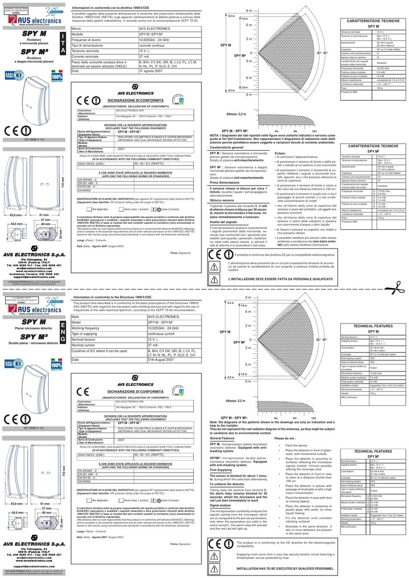
AVS Electronics SPY M User manual

AVS Electronics
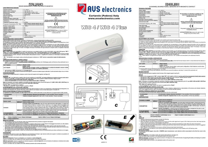
AVS Electronics WIC 4 User manual

AVS Electronics
AVS Electronics BM60HP User manual

AVS Electronics
AVS Electronics WING WS User manual

AVS Electronics
AVS Electronics SPECTRUM DT AM User manual

AVS Electronics
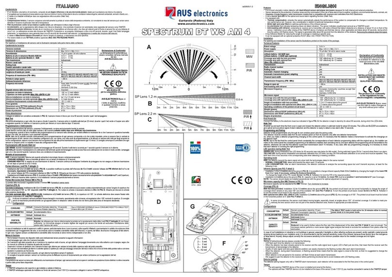
AVS Electronics SPECTRUM DT WS AM 4 User manual

AVS Electronics
AVS Electronics JET DT User manual

AVS Electronics
AVS Electronics ONE PA User manual

AVS Electronics
AVS Electronics OUTSPIDER DT User manual

AVS Electronics
AVS Electronics ONE PA WS 4 User manual