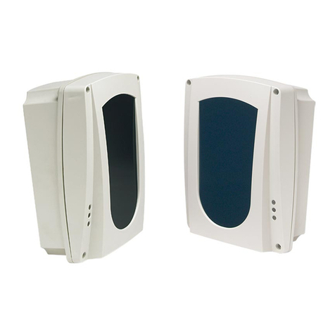
AVS Electronics SPY M User manual

AZIENDA CON SISTEMA
QUALITA’ CERTIFICATO
ISO9001
SPY MSPY M
SPY MSPY M
SPY M
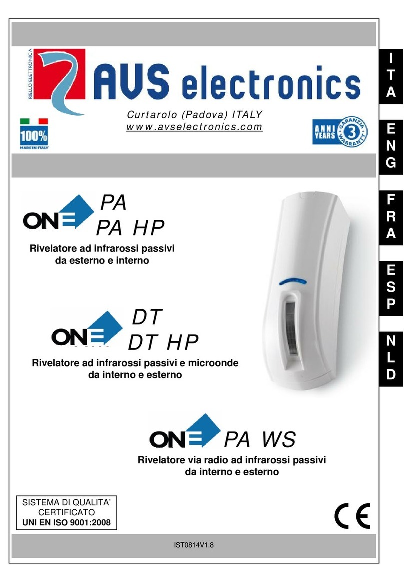
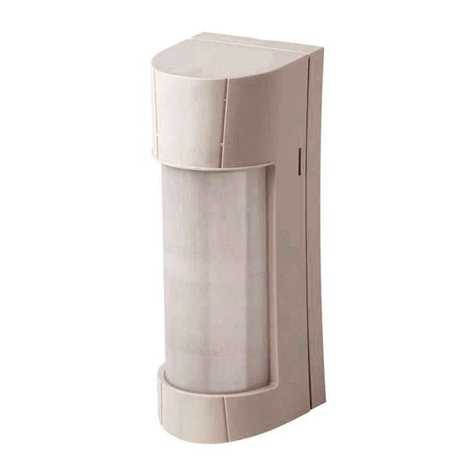
Rivelatore
a microonda planare
SPY M²SPY M²
SPY M²SPY M²
SPY M²
Rivelatore
a doppia microonda planare
IST 0698 V 1/0
L’AVS ELECTRONICS S.p.a. si riserva il diritto di apportare
modifiche in qualsiasi momento e senza preavviso.
AA
AA
AVS ELECTRVS ELECTR
VS ELECTRVS ELECTR
VS ELECTRONICS SONICS S
ONICS SONICS S
ONICS S.p.p
.p.p
.p.A..A.
.A..A.
.A.
Via Valsugana, 63Via Valsugana, 63
Via Valsugana, 63
35010 (Padova) ITALY35010 (Padova) ITALY
35010 (Padova) ITALY
Tel. 049 9698 411 / Fax. 049 9698 407Tel. 049 9698 411 / Fax. 049 9698 407
Tel. 049 9698 411 / Fax. 049 9698 407
www.avselectronics.comwww.avselectronics.com
www.avselectronics.com
Assistenza Tecnica: 049 9698 444Assistenza Tecnica: 049 9698 444
Assistenza Tecnica: 049 9698 444
Informazioni in conformità con la direttiva 1999/5/CEE
Il prodotto oggetto della presente dichiarazione è conforme alle prescrizioni fondamentali della
Direttiva 1999/5/CEE (R&TTE) sugli apparati radiotrasmittenti di debole potenza e sull’uso delle
frequenze dello spettro radioelettrico, in accordo anche con la raccomandazione CEPT 70-03.
acraM SCINORTCELESVA
olledoM ²MYPS-MYPS
orovalidezneuqerF zHG42-zhG525,01
enoizatnemilaidopiT aunitnocetnerroc
elanimonenoisneT V21
elanimonetnerroC Am73
èevodaeporueàtinumocallediseaP )ELGIS(otazzilitueressedaotanitsed ,M,TL,LF,VL,I,SI,RG,KD,YC,HiB,B HC,E,OLS,P,LP,LN,N
ataD 7002otsoga13
DICHIARAZIONE DI CONFORMITÀ
(MANUFACTURERS DECLARATION OF CONFORMITY)
DICHIARA CHE LA SEGUENTE APPARECCHIATURA
(DECLARES THAT THE FOLLOWING EQUIPMENT)
RISULTA CONFORME CON QUANTO PREVISTO DALLE SEGUENTI DIRETTIVE COMUNITARIE:
(IS IN ACCORDANCE WITH THE FOLLOWING COMMUNITY DIRECTIVES)
E CHE SONO STATE APPLICATE LE SEGUENTI NORMATIVE
(APPLYING THE FOLLOWING NORMS OR STANDARDS)
IDENTIFICATORE DI CLASSE DEL DISPOSITIVO (per apparati RF regolamentati dalla direttiva R&TTE)
(Equipment class identifier (RF products falling under the scope of R&TTE))
Il costruttore dichiara sotto la propria responsabilità che questo prodotto é conforme alla direttiva
93/68/EEC (marcatura) e soddisfa i requisiti essenziali e altre prescrizioni rilevanti della direttiva
1999/5/EC (R&TTE) in base ai risultati dei test condotti usando le normative (non) armonizzate in
accordo con le Direttive sopracitate.
(We declare under our sole responsibility that this product is in conformity with directive 93/68/EEC (Marking)
and/or complies to the essential requirements and all other relevant provisions of the 1999/5/EC (R&TTE)
based on test results using (non)harmonized standards in accordance with the Directives mentioned)
Luogo (Place) : Curtarolo
Data (Date) : Agosto 2007 (August 2007)
Firma (Signature)
erotturtsoC )rerutcafunaM( APSSCINORTCELESVA
ozziridnI )sserddA( YLATI-)DP(oloratruC01053-36,anaguslaVaiV
:arutaihccerappA’lledemoN )emaNtnempiuqE( :²MYPS-MYPS
arutaihccerappAidopiT )tnempiuqEfoepyT( : ADNOORCIMAIPPODEALOGNISAOCIRTEMULOVEROTALEVIR )ROTCETEDNOITOMEVAWORCIMLAUDDNAEVAWORCIM(
olledoM )ledoM( :
enoizurtsoCidonnA )erutcafunaMforaeY( :7002
.)CME(CE/801/4002 )ETTR&R(CE/50/99
2-044003NE 3-984103NE 4-03105NE 05906NE
elbacilppAtoN )tcudorp1ssalc(enoN X)tcudorp2ssalc(
Il prodotto è conforme alla direttiva CE per la compatibilità elettromagnetica.
L’alimentazione deve provenire da un circuito a bassissima tensione di sicurez-
za ed avente le caratteristiche di una sorgente a potenza limitata protetta da
fusibile.
L’INSTALLAZIONE DEVE ESSERE FATTA DA PERSONALE QUALIFICATO
Caratteristiche generali
SPY M : Sensore volumetrico a microonda
planare gestito da microprocessore.
Dotato di sistema anti-mascheramento.
SPY M² : Sensore volumetrico a doppia
microonda planare gestito da microproces-
sore.
Dotato di sistema anti-mascheramento.
Prima Alimentazione
Il sensore rimane in blocco per circa 1
minuto, durante il quale i led lampeggiano
alternativamente.
Sblocco sensore
Togliendo il positivo dal morsetto B, il relè
di allarme rimane in blocco per 30 secon-
di, mentre la microonda e il led rosso ini-
ziano immediatamente a fuzionare.
Analisi del segnale
Il microprocessore analizza costantemente
i segnali provenienti dalla microonda, ve-
nendo così confrontati con i parametri pre-
stabiliti; solo quando, i parametri, risulteran-
no validi nello stesso istante, si attiverà il
relè di allarme e si accenderà il led rosso.
Evitare:
• di verniciare l‘apparecchiatura
• di posizionare il sensore di fronte a delle pa-
reti o vetrate al cui esterno vi sia movimento
• di posizionare il sensore in prossimità di su-
perfici riflettenti i segnali a microonde (me-
talli, specchi, ecc.) che possano alterarne la
zona di copertura
• di posizionare il sensore di fronte o vicino a
dei neon ad una distanza inferiore a 150 cm.
• di posizionare il sensore in luoghi ove vi sia il
passaggio di piccoli animali o vi sia un‘ele-
vata concentrazione di insetti
• che all‘interno della zona di copertura del
sensore vi siano dei ventilatori, od oggetti che
possano muoversi
• che all‘interno della zona di copertura del
sensore vi siano delle tubazioni in plastica
con scorrimento d‘acqua o altro liquido
• di fissare il sensore su superfici non stabili o
che possano vibrare
• è possibile installare più sensori nello stesso
ambiente a condizione che non siano orien-
tati sulla stessa direttrice d’emissione
#
IST 0641 V 2/0
AVS ELECTRONICS S.p.A. reserves the right to modify the
technical and esthetical characteristic of the products at any time.
AA
AA
AVS ELECTRVS ELECTR
VS ELECTRVS ELECTR
VS ELECTRONICS SONICS S
ONICS SONICS S
ONICS S.p.p
.p.p
.p.A..A.
.A..A.
.A.
Via Valsugana, 63Via Valsugana, 63
Via Valsugana, 63
35010 (Padova) ITALY35010 (Padova) ITALY
35010 (Padova) ITALY
Tel. 049 9698 411 / Fax. 049 9698 407Tel. 049 9698 411 / Fax. 049 9698 407
Tel. 049 9698 411 / Fax. 049 9698 407
www.avselectronics.comwww.avselectronics.com
www.avselectronics.com
Information in conformity to the Directives 1999/5/CEE
The product here described is in conformity to the basic prescriptions of the Directives 1999/5/
CEE (R&TTE) with regard to the low-power radio-emittting devices and with regard to the use of
frequencies of the radio-electrical spectrum, according to the CEPT 70-03 reccomandation.
kraM SCINORTCELESVA
ledoM ²MYPS-MYPS
ycneuqerfgnikroW zHG42-zHG525,01
gniylppusfoepyT tnerrucsuounitnoc
noisnetlanimoN V21
tnerruclanimoN Am73
desuebnactierehwCEfoseirtnuoC ,LF,VL,I,SI,RG,KD,YC,HiB,B HC,E,OLS,P,LP,LN,N,M,TL
etaD 7002tsuguAht13
The product is in conformity to the CE directive for the electromagnetic
compatibility
Supplying must come from a very low security-tension circuit featuring a
limited-power source protected by fuse
INSTALLATION HAS TO BE EXECUTED BY QUALIFIED PERSONNEL
General Features
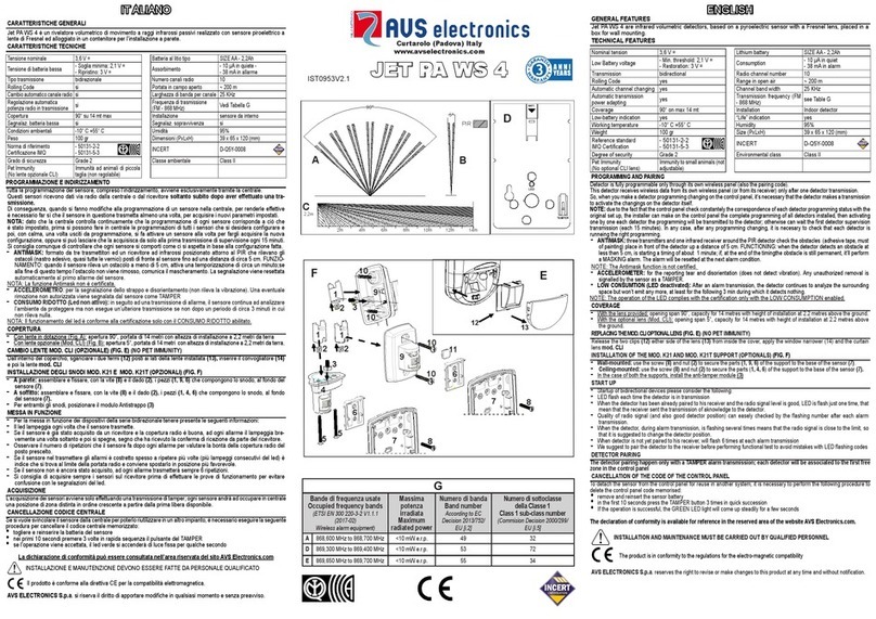
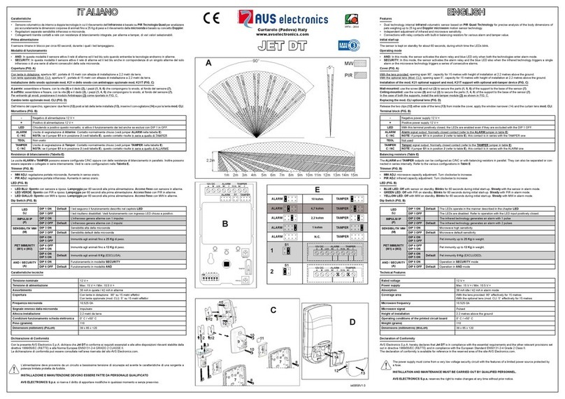
SPY M: microprocessor planar-microwave
volumetric detector. Equipped with anti-
masking system.
SPYM²: microprocessor double planar-
microwave volumetric detector. Equipped
with anti-masking system.
First Supplying
The sensor is blocked for about 1 minu-
te, during which the Leds flash alternatively
To unblock the detector
Taking away the positive from terminal B,
the alarm relay remains blocked for 30
seconds, whilst the microwave and the
red Led start immediately to work
Signal analyse
The microprocessor constantly analyses the
signals coming from the microwave which
are so compared to the pre-set parameters;
only when the parameters are valid in the
same moment , the alarm relay will activate
and the red Led will light up.
Please do not :
•Paint the device
•Place the detector in front of glass-
walls, with movements outside
•Place the detector in proximity to
surfaces reflecting the microwave
signals (metals, mirrors) possibly
altering the coverage area
•Place the detector in front or near
to neon at a distance shorter than
150 cm
•Place the detector in places with
passage of small pets or with a high
insect concentration
•Place the detector in area with fans
or moving objects
•Place the detector in presence of
plastic pipes with water (or other
liquid) flowing
•Fix the detector onto unstable
vibrating surfaces
•Orientate in the same direction if
two or more detectors are present
in the same area
A COMPANY WITH
CERTIFIED SYSTEM OF QUALITY
ISO9001
I
T
A
E
N
G
57.0841
46.0841
31.9484
46 mm
57 mm
32 mm
44,6
44,6 mm
45,8 mm
110 mm
61 mm
NOTA: I diagrammi dei lobi riportati nelle figure sono soltanto indicativi e servono come
guida ai fini dell’installazione. Non rappresentano il diagramma di radiazione reale delle
antenne perchè potrebbero essere soggette a variazioni dovute al contesto ambientale.
SPY MSPY M
SPY MSPY M
SPY M
Planar microwave detector
SPY M²SPY M²
SPY M²SPY M²
SPY M²
Double planar - microwave detector
IST 0698 V 1/0
57.0841
46.0841
31.9484
46 mm
57 mm
32 mm
44,6
44,6 mm
45,8 mm
110 mm
61 mm
SPY M - SPY M²: 4m 8m 12m
Altezza: 2,2 m
0
3 m
9 m
6 m
8,5 m 7,8 m
9 m
6 m
3 m
8,5 m 7,8 m
SPY M
SPY M² 90°80°
SPY M - SPY M²: 4m 8m 12m
Altezza: 2,2 m
0
3 m
9 m
6 m
8,5 m 7,8 m
9 m
6 m
3 m
8,5 m 7,8 m
SPY M
SPY M² 90°80°
EHCINCETEHCITSIRETTARAC ²MYPS
elanimonenoisneT V21
enoizatnemilaidenoisneT V51:xaM V5,01:niM
otnemibrossA eteiuqniAm62 emrallaniAm73
arutrepoC ivitteffeirtem21us°08
otnemarehcsam-itnaametsiS IS
erosnesoccolbossergnI IS
elangesledehcitsirettaraC adnoorcimalladosseme otaslupmI
ednoorcimazneuqerF A
BzHG525.01 zHG42
ataidarriaidemaznetoP A
BWm4.0 Wm6.1
ataidarrioccipidaznetoP A
BWm01 Wm04
:enoizallatsniazzetlA tm2,2a9,1adatailgisnoc
:ilatneibmainoizidnoC C°04+/°5+
oseP g501
QMIinoizatserP
EHCINCETEHCITSIRETTARAC MYPS
:elanimonenoisneT V21
:enoizatnemilaidenoisneT V51:xaM V5,01:niM
otnemibrossA eteiuqniAm22 emrallaniAm82
arutrepoC ivitteffeirtem21us°09
otnemarehcsam-itnaametsiS IS
erosnesoccolbossergnI IS
elangesledehcitsirettaraC adnoorcimalladosseme otaslupmI
adnoorcimazneuqerF zHG525.01
ataidarriaidemaznetoP Wm4.0
ataidarrioccipidaznetoP Wm01
:enoizallatsniazzetlA tm2,2a9,1adatailgisnoc
:ilatneibmainoizidnoC C°04+/°5+
oseP g001
QMIinoizatserP
SERUTAEFLACINHCET ²MYPS
:noisnetlanimoN V21
:noisnetgnilppuS V51:xaM V5,01:niM
noitpmusnoC tsertaAm62 mralaniAm73
egarevoC sretemevitceffe21no°08
metsysgniksam-itnA SEY
kcolbrotcetedfotupmI SEY
ybdettimelangisfoepyT evaworcim desluP
ycneuqerfevaworciM A
BzHG525.01 zHG42
detaidarrirewopmuideM A
BWm4.0 Wm6.1
detaidarrirewopkaeP A
BWm01 Wm04
:thgiehnoitallatsnI sretem2,2ot9,1morf:detsegguS
erutarepmetgnikroW C°04+/°5+
thgieW g501
noitacifitrecQMI
SERUTAEFLACINHCET MYPS
:noisnetlanimoN V21
:noisnetgnilppuS V51:xaM V5,01:niM
noitpmusnoC tsertaAm22 mralaniAm82
egarevoC sretemevitceffe21no°09
metsysgniksam-itnA SEY
kcolbrotcetedfotupmI SEY
ybdettimelangisfoepyT evaworcim desluP
ycneuqerfevaworciM zHG525.01
detaidarrirewopmuideM Wm4.0
detaidarrirewopkaeP Wm01
:thgiehnoitallatsnI sretem2,2ot9,1morf:detsegguS
erutarepmetgnikroW C°04+/°5+
thgieW g001
noitacifitrecQMI
DICHIARAZIONE DI CONFORMITÀ
(MANUFACTURERS DECLARATION OF CONFORMITY)
DICHIARA CHE LA SEGUENTE APPARECCHIATURA
(DECLARES THAT THE FOLLOWING EQUIPMENT)
RISULTA CONFORME CON QUANTO PREVISTO DALLE SEGUENTI DIRETTIVE COMUNITARIE:
(IS IN ACCORDANCE WITH THE FOLLOWING COMMUNITY DIRECTIVES)
E CHE SONO STATE APPLICATE LE SEGUENTI NORMATIVE
(APPLYING THE FOLLOWING NORMS OR STANDARDS)
IDENTIFICATORE DI CLASSE DEL DISPOSITIVO (per apparati RF regolamentati dalla direttiva R&TTE)
(Equipment class identifier (RF products falling under the scope of R&TTE))
Il costruttore dichiara sotto la propria responsabilità che questo prodotto é conforme alla direttiva
93/68/EEC (marcatura) e soddisfa i requisiti essenziali e altre prescrizioni rilevanti della direttiva
1999/5/EC (R&TTE) in base ai risultati dei test condotti usando le normative (non) armonizzate in
accordo con le Direttive sopracitate.
(We declare under our sole responsibility that this product is in conformity with directive 93/68/EEC (Marking)
and/or complies to the essential requirements and all other relevant provisions of the 1999/5/EC (R&TTE)
based on test results using (non)harmonized standards in accordance with the Directives mentioned)
Luogo (Place) : Curtarolo
Data (Date) : Agosto 2007 (August 2007)
Firma (Signature)
erotturtsoC )rerutcafunaM( APSSCINORTCELESVA
ozziridnI )sserddA( YLATI-)DP(oloratruC01053-36,anaguslaVaiV
:arutaihccerappA’lledemoN )emaNtnempiuqE( :²MYPS-MYPS
arutaihccerappAidopiT )tnempiuqEfoepyT( : ADNOORCIMAIPPODEALOGNISAOCIRTEMULOVEROTALEVIR )ROTCETEDNOITOMEVAWORCIMLAUDDNAEVAWORCIM(
olledoM )ledoM( :
enoizurtsoCidonnA )erutcafunaMforaeY( :7002
.)CME(CE/801/4002 )ETTR&R(CE/50/99
2-044003NE 3-984103NE 4-03105NE 05906NE
elbacilppAtoN )tcudorp1ssalc(enoN X)tcudorp2ssalc(
Note: the diagrams of the patterns shown in the drawings are only an indication and a
help to the installer.
They do not represent the real radiation diagram of the antennas, as they might be subject
to variations due to environmental context.
www.avselectronics.com

3- BASE SENSORE
AeterapaoiggassiflireporoF
B°54idelaretalenoizanilcninoceterapaoiggassiflirepiroF
CovacassapelanaC
DodonsolotazzilitueneivesovacassaporofoeterapaesaballedoiggassifreporoF
EodonsollaesaballedoiggassiflirepiroF
FoihcrepocledoccolblirepetiV
GovacassaporofrepotivnI
Prima di effettuare le operazioni descritte successivamente, assicu-
rarsi di aver estratto la scheda elettronica dalla base per evitare di
danneggiarla.
1- PARAMETRI DI FUNZIONAMENTO
•Durata dell’impulso: la durata di ogni impulso deve rientrare in una determinata fine-
stra temporale.
•Ampiezza dell’impulso: l’ampiezza del segnale deve essere superiore ad una gran-
dezza prefissata, per evitare allarmi indesiderati.
•Distanza relativa tra impulsi: il segnale viene riconosciuto come valido soltanto se
almeno due impulsi sono compresi in un determinato intervallo di tempo.
2- CONSIGLI PER L’INSTALLAZIONE
•Scegliere con cura la posizione del sensore, tenendo presente che la microonda rile-
va con maggiore sensibilità i movimenti di avvicinamento e allontanamento dal sensore
e con minore sensibilità i movimenti trasversali.
•Fissare il sensore su superfici stabili e prive di vibrazioni, ad un’altezza compresa tra
i 2 e 2,30 metri.
•Evitare di puntare il sensore su lampade fluorescenti.
•Usare cavo schermato (sezione 0.50mm per l’alimentazione), collegando la schermatura
al negativo soltanto nella centrale e non nel sensore.
BASE LATO ESTERNO
Eseguire un foro ( massimo Ø 12
mm) in corrispondenza della predi-
sposizione, per il passaggio del
cavo e per permettere il successi-
vo blocco dello snodo.
BASE LATO INTERNO
Eseguire i due fori Ø 3,5 mm per il
fissaggio della base sullo snodo,
nelle posizioni indicate in figura.
Utilizzare la vite di fissaggio lunga
(M3x12) dal lato del foro E2e quel-
la corta (M3x8) dal lato del foro E1.
E2
D
Una volta trovata l’inclinazio-
ne più consona per il senso-
re, fissare la vite di blocco
dello snodo (in figura è indicata
la posizione della vite di blocco).
B
C
F
C
G
E2
B
E1
A
B
D
E1
B
6 - MORSETTIERA
5- ANTISTRAPPO (Mod. KBT)
Forare la parete in corrispondenza del tamper di antistrappo
posto sul fondo dello snodo.
Avvitare sul tassello la vite a testa svasata, fino a farla
aderire al muro.
AM: Uscita Anti-mascheramento
All’alimentazione il circuito di antimascheramento esegue
un’autoregolazione. In questa fase è essenziale che il co-
perchio sia regolarmente installato per permettere al
sensore di regolarsi sul valore corretto.
Il circuito anti-mascheramento fornisce un segnale di allarme
se viene mantenuto per più di un minuto del materiale metallico
frontalmente al sensore e ad una distanza massima di 20 cm.
Il led giallo inizia a lampeggiare non appena il sensore inizia a rilevare un tentativo di maschera-
mento, se dopo un minuto la causa di mascheramento persiste, si attiva l’uscita dedicata AM che
fornisce un negativo transistorizzato ed il led giallo si accende di luce fissa.
Entrambe le segnalazioni vengono resettate automaticamente al primo allarme del sensore.
La funzione anti-mascheramento può essere attiva sia a centrale accesa che spenta.
NOTA: questa funzione non garantisce comunque che il sensore non possa essere
mascherato.
B: Ingresso di Blocco
Al morsetto (B) di blocco, deve essere fornito un positivo a centrale spenta, al fine di bloccare il
funzionamento del sensore stesso:
•Blocco del relè di allarme nella condizione di riposo (NC)
•Blocco completo dell'alimentazione della microonda
•Blocco della funzione anti-mascheramento
Se utilizzato il comando di blocco, l'attivazione del relè del sensore avviene 30 secondi
dopo la mancanza del positivo al morsetto (B).
Integrando il contatto an-
tistrappo posto sul fondo
dellosnodoalcircuitoan-
tiapertura del sensore, si ottiene una pre-
stazione al 2° Livello IMQ.
Per bloccare il coperchio, utilizzare
la vite in dotazione.
Di fabbrica la vite viene posizionata
nella base del sensore (contrassegnata con
la lettera F nella tabella BASE SENSORE) .
99
99
9
- CHIUSURA SENSORE- CHIUSURA SENSORE
- CHIUSURA SENSORE
88
88
8
--
--
- TT
TT
TARAARA
ARAARA
ARATURA DEL SENSORETURA DEL SENSORE
TURA DEL SENSORETURA DEL SENSORE
TURA DEL SENSORE
7 - DIP SWITCH, JUMPER e TRIMMER
+V21enoizatnemilaidovitisoP
-enoizatnemilaidovitageN
CAm001V21atatropnocerosnesledemrallaidottatnoC osopiraerosnesnocosuihcetnemlamroN
CN
TenoissimonamitnaidaeniL asuihcetnemlamroN
T
BoccolBidottesroM
MA otnemarehcsam-itnaaticsU
tluafedidenoizatsopmi:HCTIWSPID 1 2 3 4
MYPS FFO FFO FFO FFO
²MYPS FFO FFO FFO FFO
OTNEMAREHCSAMITNAENOIZALANGES-2PID FFO alosalladenoizavitta'lacovorperosnesledotnemarehcsamlI MAaticsu
NO aisenoizavitta'lacovorperosnesledotnemarehcsamlI emrallaidèlerledehcMAaticsu'lled
DELOTNEMANOIZNUF-1PID
NO OSSOR
OLLAIG
adnoorcimalledemrallaidenoizalangeS eroirepus adnoorcimalledemrallaidenoizalangeS )²MYPSolos(eroirefni
FFO )tluafeD( OSSOR OLLAIG erosnesledemrallaidenoizalangeS KSAMITNAemrallaidenoizalangeS
EDNOORCIMATATROP-REMMIRT 1VR )²MYPSolos( alledatatropalledenoizalogeralrepremmirT eroirefniadnoorcim Bosnesniolodnatour( .)aminimatatropaleneittoisoiraroitna
2VR alledatatropalledenoizalogeralrepremmirT eroirepusadnoorcim Aosnesniolodnatour( .)aminimatatropaleneittoisoiraroitna
3VR otasunoN
Per il corretto funzionamento del sensore, è obbligatorio eseguire la taratura.
Questa deve essere effettuata dopo almeno 1 minuto dalla prima alimentazione
o 30 secondi dallo sblocco (tolto positivo di blocco dal morsetto B).
OSSORDELFFO-1SREPMUJOSUIHC )tluafeD(otatilibaossordel
OTREPA otatilibasidossordel
3- BASE OF THE DETECTORBASE OF THE DETECTOR
BASE OF THE DETECTORBASE OF THE DETECTOR
BASE OF THE DETECTOR
AllawehtotnoitaxifrofeloH
B°54fonoitanilcnihtiwllawehtotnoitaxifrofseloH
Clennahcelbac-gnissaP
Ddesusileviwsehtfielohelbac-gnissaprollawehtotesabehtfonoitaxifrofeloH
EleviwsehtotesabehtfonoitaxifrofseloH
FgnikcolbrevocrofwercS
Gelohelbac-gnissapotediuG
Before making the following operations here described, be sure you
have taken off the electronic board from the base in order not to damage
it.
1- WORKING PARAMETERSWORKING PARAMETERS
WORKING PARAMETERSWORKING PARAMETERS
WORKING PARAMETERS
2- RECOMMANDATION FOR INSTALLATIONRECOMMANDATION FOR INSTALLATION
RECOMMANDATION FOR INSTALLATIONRECOMMANDATION FOR INSTALLATION
RECOMMANDATION FOR INSTALLATION
•Choose carefully the position of the detector, reminding that microwave detects the
movements of approaching and leaving with higher sensitivity and the crossing
movements with reduced sensitivity
•Fix the detector onto stable and no-vibrating surfaces at a height between 2 and 2,3
meters
•Do not point the detector towards fluorescent lamps
•Use shielded cable (0,5 for supplying), connecting the shield to the negative only on
the control panel, and not on the detector.
BASE - EXTERNAL SIDE
Make a hole (max Ø 12 mm) in
correspondance of the
predisposition, for the cable passing
and to then allow the block of the
swivel.
BASE - INTERNAL SIDE
Make the two Ø 3,5 mm holes to fix
the base to the swivel, as shown in
the picture.
Use the long fixing screw (M3x12)
on the side of the hole E2 and the
short one (M3x8) on the side of the
hole E1.
E2
D
Once found the right inclination
for the detector, fix the
blocking screw of the swivel
(the position of the blocking
screw is shown in the picture).
B
C
F
C
G
E2
B
E1
A
B
D
E1
B
6 - TERMINAL BOARDTERMINAL BOARD
TERMINAL BOARDTERMINAL BOARD
TERMINAL BOARD
5 - ANTI-TAMPER (KBT)ANTI-TAMPER (KBT)
ANTI-TAMPER (KBT)ANTI-TAMPER (KBT)
ANTI-TAMPER (KBT)
AM: anti-masking output
When supplied, the anti-masking circuit makes a self-adjusting.
During this operation, the cover must be regularly installed
for getting correct adjustment of the detector.
The anti-masking circuit gives an alarm indication if any
metal material is kept for over one minute in front of the
detector at the distance of max 20 cm.
The yellow Led will start flashing as soon as the detectors
identifies a masking attempt ; if the masking action persists
after one minute, a dedicated AM output will activate, giving a
transistorized negative and the yellow Led will light up.
Both indications are automatically reset at the first alarm of the detector. The anti-masking
function can be active at both armed or disarmed control panel.
Note: this function does not grant that the detector cannot be anyway masked.
B: Block Input
A positive at disarmed control panel must be given to block terminal (B), in order to block the
working of the detector itself
•Block of the alarm relay in rest condition (NC)
•Complete block of the microwave supplying
•Block of the anti-masking function
If the block command is in use, the detector relay activates 30 seconds after the positive
missing to terminal (B)
The integration of the
anti-tamper contact
placed on the bottom
of the swivel to the anti-opening
circuit of the detector, allows to obtain
the 2 level of IMQ
In order to block the cover, use the
screw given within.
At factory, the screw is positioned at the
bottom of the detector (marked by letter F in
the chart DETECTOR BASE)
99
99
9
--
--
- CLOSING OF DETECTOR
88
88
8
--
--
- ADJUSTING OF THE DETECTOR
7 - DIP-DIP-
DIP-DIP-
DIP- SWITCH AND TERMINALSWITCH AND TERMINAL
SWITCH AND TERMINALSWITCH AND TERMINAL
SWITCH AND TERMINAL
+gniylppusV21evitisoP
-gniylppusevitageN
CAm005V21tcatnocmralarotceteD rotcetedteiuqhtiwdesolcyllamroN
CN
Tenilrepmat-itnA desolcyllamroN
T
BlanimretkcolB
MA tuptuogniksam-itnA
The first adjusting must be made after at least 30 seconds since first supplying
or since the unblock (taken away the positive from the terminal B)
Per regolare la copertura dello SPY M² agire nel seguente modo:
A. Posizionare i DIP 1 in ON, in questo modo il led giallo segnala l’allarme della
microonda inferiore ed il led rosso segnala l’allarme della microonda superiore.
B. Ruotare il trimmer RV2 (massima portata in senso orario) fino ad ottenere la portata
desiderata della microonda superiore.
C. Ruotare il trimmer RV1 (massima portata in senso orario) fino ad ottenere la portata
desiderata della microonda inferiore.
D. Riportare il DIP 1 in OFF, per riattivare il normale funzionamento dei led.
N.B. Anche nella condizione di Test (DIP 1 in ON), il relè di allarme si attiva solo con
l’allarme simultaneo di entrambe le microonde.
Per regolare la copertura dello SPY M, ruotare il trimmer RV2 (massima portata in senso ora-
rio) fino ad ottenere la portata desiderata della microonda.
#
ENOIZARGETNI
3PID 4PID
FFO FFO 001 ELAMRON
NO FFO 003 ATLAOIDEM
FFO NO 006 ASSABOIDEM
NO NO 009 ASSAB
LED
GIALLO LED
ROSSO
RV2
RV1
RV3
TAMPER
S1
A
B
gnittestluafed:HCTIWSPID 1 2 3 4
MYPS FFO FFO FFO FFO
²MYPS FFO FFO FFO FFO
NOITACIDNIGNIKSAM-ITNA-2PID
FFO MAehtfonoitavitcaehtsesuacrotcetedehtfogniksamehT ylnotuptuo
NO MAehtfonoitavitcaehtsesuacrotcetedehtfogniksamehT yalermralaehtfonoitavitcaehtdnatuptuo
GNIKROWDEL-1PID
NO DER
WOLLEY
evaworcimreppuehtfonoitacidnimralA
evaworcimmottobfonoitacidnimralA )ylno²MYPS(
FFO )tluafeD( DER WOLLEY rotcetedehtfonoitacidnimralA noitacidnimralaKSAMITNA
EGNAREVAWORCIM-REMMIRT
1VR )ylno²MYPS( mottobfognitsujdaegnarrofremmirT evaworcim Besiwkcolc-itnanignitator( .))deniatbosiegnartsewolehtesnes
2VR reppufognitsujdaegnarrofremmirT evaworcim Aesiwkcolc-itnanignitator( .)deniatbosiegnartsewolehtesnes
3VR desutoN
FFODELDER-1SREPMUJ
DESOLC )tluafeD(delbanedeLdeR
NEPO delbanetondeLdeR
NOITARGETNI
3PID 4PID
FFO FFO 001 LAMRON
NO FFO 003 HGIHMUIDEM
FFO NO 006 WOLMUIDEM
NO NO 009 WOL
YELLOW
LED RED
LED
RV2
RV1
RV3
TAMPER
S1
A
B
•Duration of the pulse: the duration of the pulse must be within a certain time lapse.
•Amplitude of the pulse: the amplitude of the signal must be wider than a pre-fixed
value, in order to avoid false alarms
•Distance between the pulses: the signal is recognized as valid only if at least two
pulses are included in a certain time lapse.
Make a hole in the wall in correspondence of the anti-tamper
placed on the bottom of the swivel.
Screw until reaching adherence to the wall
Act as follows in order to adjust the SPY M² coverage
A. Position DIP 1 in ON, in this way the yellow Led indicates the alarm of the bottom
microwave and the red Led indicates the alarm of the upper microwave
B. Rotate the RV2 trimmer (max range in clockwise sense) until reaching the range
required on the upper microwave
C. Rotate the RV1 trimmer (max range in clockwise sense) until reaching the range
required on the bottom microwave
D. Set again DIP 1 on OFF in order to re-activate the normal working of Leds
Note: Also in Test condition (DIP1 on ON), the alarm relay activates only with
contemporary alarm of both microwaves
In order to adjust SPY M coverage, rotate RV2 trimmer (max range in clockwise sense) until
reaching the range required
4- SWIVEL ( KB AND KBT)SWIVEL ( KB AND KBT)
SWIVEL ( KB AND KBT)SWIVEL ( KB AND KBT)
SWIVEL ( KB AND KBT)
Insert the nut of swivel
movement-block in its seat
46.0841
46 mm
For the passage
of the cable and
of tamper wires,
use the passage
shown in the picture
For fixing the swivel to the wall and for anti-tamper reference
screw, use the screws given within.
PAY ATTENTION
In order to make the fixing holes for the
swivel and the reference hole for anti-
tamper screw, use the hole-diagram
printed inside the packaging
Secure well
nut of
swivel
movement-
block with the
screw given within
4- SNODO (Mod. KB e Mod. KBT)
Inserire il dado di blocco del movi-
mento dello snodo nella propria sede
46.0841
46 mm
Perilpassaggio del
cavo e dei fili del-
l’antistrappo, utiliz-
zare il passaggio in-
dicato in figura.
Per il fissaggio dello snodo a parete e per la vite di riferimento
dell’antistrappo, utilizzare i tasselli e le viti in dotazione.
ATTENZIONE
Per effettuare i fori di fissaggio dello
snodo e il foro di riferimento per la vite
dell’antistrappo, si può utilizzare la dima
di foratura stampata all’interno della
scatola dell’imballo del sensore
Fissare bene il
dado di bloc-
co del movi-
mento dello
snodo con la vite
M3x16 in dotazione
This manual suits for next models
1
Other AVS Electronics Security Sensor manuals

AVS Electronics
AVS Electronics JET DT User manual

AVS Electronics
AVS Electronics WING WS User manual

AVS Electronics
AVS Electronics SPECTRUM PA WALL User manual

AVS Electronics
AVS Electronics SPECTRUM DT AM User manual

AVS Electronics
AVS Electronics JET DT WS 4 User manual

AVS Electronics
AVS Electronics SPECTRUM DT WS AM 4 User manual

AVS Electronics
AVS Electronics BF100 R User manual

AVS Electronics
AVS Electronics ONE PA WS 4 User manual

AVS Electronics
AVS Electronics OUTSPIDER DT User manual

AVS Electronics
AVS Electronics WIC 4 User manual