ESPAÑOLDEUTSCHFRANÇAIS
Caractéristiques
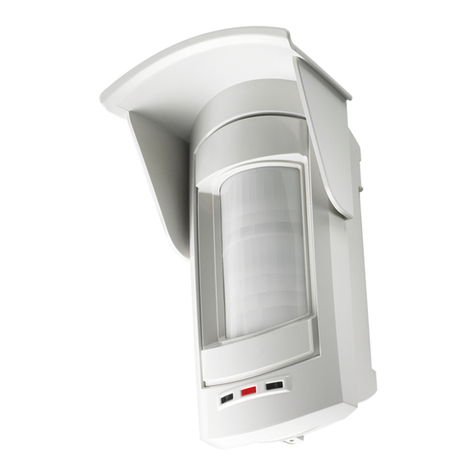
- Détecteur volumétrique de mouvement, avec connexion laire, constitué d’un double infrarouge conçu pour la protection intérieure et
extérieure.
- Détecteur conçu pour la protection des zones extérieures et la minimisation des risques d’alarmes intempestives causées par les con-
ditions météorologiques, les éléments environnementaux, les animaux en liberté, etc.
- Il est équipé d’un buzzer et d’une led qui donnent une signalisation optique-acoustique (test de déplacement).
- Il est également doté de:
• Compensation thermique, le capteur règle automatiquement la portée selon la température ambiante, toutefois le rendement du
capteur peut varier sensiblement en fonction d’intervalles de températures particuliers.
• Filtres de protection contre la lumière blanche et celle solaire, an d’optimiser la lecture des infrarouges
• Accéléromètre (seul le mod. Spectrum PA WALL AM), pour l’indication de tout arrachement (il ne détecte pas la vibration). Un
éventuel sabotage non autorisé est signalé par le capteur comme TAMPER.
• Anti-masquage infrarouge (seul le mod. Spectrum PA WALL AM), constitué d’un récepteur RX et deux transmetteurs TX à infra-
rouges actifs des deux côtés, pour détecter les obstacles devant le capteur jusqu’à une distance d’environ 7 cm. L’étalonnage est
effectué à la fermeture du TAMPER (Boîtier et, le cas échéant, Anti-arrachement) et dure environ 40 secondes, au cours desquelles la
led jaune clignote lentement. L’indication est générée après environ 30 secondes après la détection de l’obstacle, pendant lesquelles
la led jaune clignote rapidement, si entretemps le capteur ne génère pas d’alarmes. Lors de l’indication d’anti-masquage, la led jaune
reste xe. La signalisation est remise à zéro après l’élimination de l’obstacle.
REMARQUE : si la LED JAUNE reste allumée FIXE pendant la phase d’Étalonnage Anti-masque, cela signie que le capteur n’est
pas en mesure d’effectuer correctement la procédure en raison de la lumière du soleil qui frappe la lentille ; ouvrir puis refermer le
TAMPER et répéter la procédure en faisant de l’ombre au capteur.
- Il est doté d’une entrée auxiliaire AUX (seul le mod. Spectrum PA WALL AM) pour gérer une entrée d’alarme supplémentaire ou le
circuit d’anti-arrachement du capteur même
- Il est doté de Masques Adhésifs pour masquer l’un des deux côtés.
- Il peut être protégé par une TOITURE optionnelle (Mod. SSC PROTECTION FRONT)
Installation
Pour l’ouverture et l’installation du capteur voir les illustrations imprimées à l’intérieur de l’emballage.
Caractéristiques techniques
Tension nominale 12 V =
Tension d’alimentation Max : 15 V = / Min : 10,5 V =
Absorption 25 mA au repos / 31 mA en alarme
Couverture 10° sur 12 mètres effectifs dans les deux côtés opposés
Anti-masquage infrarouge oui (seul le mod. Spectrum PA WALL AM)
Hauteur installation 1,2 mètres du sol
Conditions de fonctionnement carte électronique -25° C / +55° C
Poids (grammes) 260
Dimensions sans TOITURE (millimètres) (PxLxH)
Dimensions avec TOITURE (millimètres) (PxLxH) 68,3 x 75,4 x 189,4
87,3 x 75,4 x 189,4
Indice de protection IP55
Première alimentation
Le capteur reste en position de blocage pendant environ 60 secondes, pendant lesquelles les leds clignotent.
Mode de fonctionnement
Le capteur active le relais d’alarme et la LED bleue lorsque l’un des capteurs disposés sur les côtés opposés entrer en mode d’alarme.
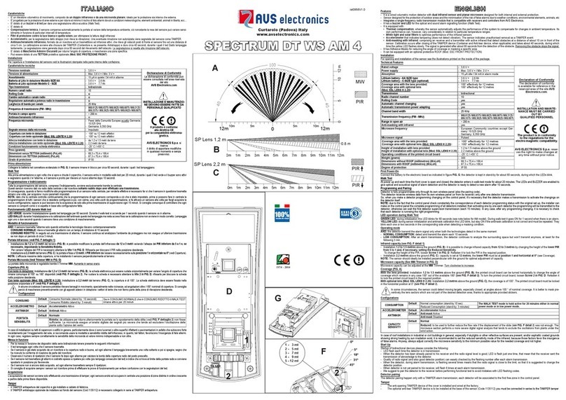
Portée infrarouge (voir la FIG. F détail 1)
- Installation de 1,2 à 1,5 mètres du sol (FIG. B) : il est possible de modier la portée de l’infrarouge de 12 à 3 mètres en variant la hauteur
du PIR inférieur de 1 à 5.
Pour varier la hauteur du PIR il faut desserrer la Vis 1 à la FIG. D. La xer pour bloquer le PIR dans la position souhaitée.
REMARQUE : Le réglage optimal de la portée est possible en installant le capteur perpendiculairement au sol.
Couverture (Fig. A)
La couverture est de 10° sur les deux côtés. La carte électronique doit être xée en position horizontale à 0° (voir la FIG. F détail 2).
Bornier (Fig. B)
-Négatif d'alimentation 12 V =
+Positif d'alimentation 12 V =
C / NC Sortie d’indication Alarme. Contact normalement fermé (voir cavalier ALARM au tableau E)
REMARQUE : si le cavalier S1 est sur la position 2 (voir tableau E), ce contact est en série avec le TAMPER
AM AM Sortie d’indication Anti-masquage (seul le mod. Spectrum PA WALL AM).
Contact normalement fermé (voir cavalier ANTIMASK au tableau E)
T T Sortie d’indication de Tamper. Contact normalement fermé (voir cavalier TAMPER au tableau E)
REMARQUE : si le cavalier S1 est sur la position 2 (voir tableau E), ce contact est en série avec l’ALARME
BEntrée qui permet au capteur d’avoir la référence du statut de la centrale. Pour gérer cette information, avec centrale
éteinte, cette entrée doit être fermée sur positif (seul le mod. Spectrum PA WALL AM).
Dans cet état, le relais d’alarme reste fermé, la micro-onde est désactivée, et, en cas d’alarme, la led et le buzzer ne sont
pas activés
AUX AUX est une entrée avec référence négative qui active le relais d’Alarme ou celui de Tamper (voir DIP 5)
(seul le mod. Spectrum PA WALL AM)
Résistances d’équilibrage (Tableau E)
Les sorties ALARM, TAMPER et ANTIMASK (seul le mod. Spectrum PA WALL AM) peuvent être congurées C/NC (Cavalier ouvert) ou
avec des résistances d’équilibrage en parallèle (Cavalier fermé selon la valeur de résistance à programmer). En outre, elles peuvent être
séparées ou connectées en série à l’intérieur.
Des exemples de conguration sont indiqués dans le tableau E :
Schéma 1. Les contacts d’Alarme, Tamper et Antimask sont indépendants entre eux
Schéma 2. Les contacts d’Alarme et Tamper sont en série entre eux (il faut insérer une des quatre résistances dans le circuit Tamper).
L’Antimask est indépendant.
Schéma 3. Les contacts d’Alarme et Antimask sont en série entre eux Le Tamper est indépendant.
Schéma 4. Les contacts d’Alarme, Tamper et Antimask sont en série entre eux (il faut insérer une des quatre résistances dans le circuit Tamper).
LED (FIG. D)
-LED BLEUE: Éteinte lorsque le capteur est au repos. Clignotante pendant 60 secondes lors de la première mise sous tension. Allumée
xe lorsque le capteur est en alarme.
-LED JAUNE (Antimask) (seul le mod. Spectrum PA WALL AM): Éteinte au repos. Clignotante lentement pendant 40 secondes lors
de l’Étalonnage. Clignotante rapidement pendant 30 secondes lors de la détection d’un obstacle. Allumée xe avec Antimask en alarme.
Dip Switch (FIG. D)
Pour accéder aux dip-switch, retirer le miroir en le faisant glisser avec précaution vers le haut (voir Fig. D, Détail 3)
DIP 1 SENSIBILITÉ IR ON Sensibilité de l’Infrarouge faible Déclaration de conformité
La déclaration de conformité peut être
consultée dans l’espace Membres
du site AVS Electronics.com.
L’alimentation doit dériver d’un circuit à
très faible tension de sécurité et ayant
les caractéristiques d’une source à puis-
sance limitée protégée par un fusible.
L’INSTALLATION ET L’ENTRETIEN
DOIVENT ÊTRE CONFIÉS
À UN PERSONNEL QUALIFIÉ
OFF Default Sensibilité de l’Infrarouge normale
DIP 2 ENTRÉE AUX
(Habilitation) ON Gestion entrée AUX activée
OFF Default Gestion entrée AUX désactivée
DIP 3 ANTIMASK ON Default Antimask activé
OFF Antimask exclu
DIP 4 ACCÉLÉROMÈTRE ON Default Accéléromètre activé
OFF Accéléromètre exclu
DIP 5 ENTRÉE AUX
(Gestion)
ON L'entrée AUX active le relais d'Alarme
OFF Default L'entrée AUX active le relais de Tamper
DIP 6 LED BLEUE ON Default Led Bleue activée
OFF Led Bleue exclue
DIP 7 LED JAUNE ON Default Led Jaune activée
OFF Led Jaune exclue
DIP 8 BUZZER ON Default Buzzer activée
OFF Buzzer exclue
En général, dans le cas d’installations sur les toits de bâtiments industriels ou civils, mais, en particulier, en présence de puits de lumière
ou d’autres surfaces rééchissantes et/ou de sols bitumeux enrobés, présentant de forts échauffements par irradiations solaires, réduire
la sensibilité de l’infrarouge, car ces facteurs favorisent l’apparition d’alarme intempestives. Dans tous les cas, il est nécessaire de toujours
régler la sensibilité de l’hyperfréquence à la valeur minimale possible, tout en couvrant la zone de détection selon le besoin – et non plus.
Tamper
- Le TAMPER anti-ouverture du couvercle est déjà installé et câblé à l’usine.
- Le TAMPER anti-ouverture optionnel doit être installé sur le fond du capteur (Code1135112) et une connexion entre les bornes AUX
et - (négatif) est conseillée
AVS ELECTRONICS S.p.a. se réserve le droit d’apporter des modications à tout moment et sans préavis.
Merkmale
- Es handelt sich um einen volumetrischen Bewegungsmelder mit Drahtanschluss, bestehend aus einem doppelten Infrarotsensor. Er
eignet sich sowohl für die Innen- als auch für die Außenüberwachung.
- Der Sensor wurde für den Schutz des Außenbereichs entwickelt und die minimiert das Risiko von Falschalarmen aufgrund von Wetter-
bedingungen, Umwelteigenschaften, Tieren usw.
- Durch die Ausstattung mit Summer und Led wird eine akustische und optische Meldung erzeugt (Walk Test).
- Bestandteile:
• Wärmeausgleicher. Der Sensor gleicht automatisch die Reichweite bei Veränderungen der Raumtemperatur aus. Trotzdem kann
die Leistung des Sensors in Funktion spezieller Temperaturintervalle empndlich schwanken.
• Schutzlter gegen weißes und Sonnenlicht. Dadurch wird die Infratroterfassung optimiert.
• Beschleunigungsmesser (nur das mod. Spectrum PA WALL AM). Dieser meldet ruckweise Veränderungen (Vibrationen werden
nicht ermittelt). Eine allfällige nicht autorisierte Entfernung wird vom Sensor als TAMPER gemeldet.
• Infrarot-Abdeckungsschutz (nur das mod. Spectrum PA WALL AM).Dieser besteht aus einem RX-Empfänger und zwei TX-Sender
mit aktiven Infrarotstrahlen auf beiden Seiten, welche die vor dem Sensor bendlichen Hindernisse bis zu einem Abstand von zirka 7
cm ermitteln. Die Kalibrierung erfolgt bei Schließung des TAMPERs (Behälter und, falls vorhanden, Abrissschutz) und dauert ca. 40
Sekunden. Während dieser Zeit blinkt die gelbe Led langsam. Die Meldung wird etwa 30 Sekunden nach Ermitteln des Hindernisses
erzeugt, während welcher die gelbe Led schnell blinkt, wenn der Sensor in der Zwischenzeit keinen Alarm erzeugt. Während der Mel-
dung des Abdeckungsschutzes leuchtet die gelbe Led durchgehend auf. Nach Entfernen des Hindernisses wird die Meldung quittiert.
HINWEIS: Wenn die GELBE LED bei der Antimask-Kalibration mit DAUERLICHT brennt, kann der Sensor den Vorgang nicht
richtig ausführen, da Sonnenlicht auf die Linse scheint. Den TAMPER öffnen und schließen und den Vorgang wiederholen, dabei
muss der Sensor im Schatten liegen.
- Der Bewegungsmesser ist mit einem Hilfseingang AUX ausgestattet (nur das mod. Spectrum PA WALL AM), um einen zusätzlichen
Alarmeingang oder den Rissschutzkreis des Sensors selbst verwalten zu können.
- Er verfügt außerdem über Verdunkelungs-Klebemasken, einer der beiden Seiten zu überdecken.
- Er kann auf Anfrage mit einem SCHUTZDACH ausgerüstet werden (Mod. SSC «FRONT»-SCHUTZ)
Installation
Siehe Zum Öffnen und Montage des Sensors die Abbildungen auf der Innenseite der Packung gedruckt.
Technische Merkmale
Nennspannung 12 V =
Speisespannung max: 15 V = / min: 10,5 V =
Aufnahmeleistung 25 mA im Ruhezustand / 31 mA im Alarmzustand
Geschützter
10° auf 12 effektiven Metern in den beiden gegenüberliegenden Seiten
Infrarot-Abdeckungsschutz ja (nur das mod. Spectrum PA WALL AM)
Einbauhöhe 1,2 m vom Boden
Betriebsbedingungen Elektronikkarte -25° C / +55° C
Gewicht (in Gramm) 260
Abmessungen ohne SCHUTZDACH (Millimeter) (TxLxH)
Abmessungen mit SCHUTZDACH (Millimeter) (TxLxH) 68,3 x 75,4 x 189,4
87,3 x 75,4 x 189,4
Schutzgrad IP55
Erster Anschluss
Der Sensor bleibt ca. 60 Sekunden lang blockiert. Während dieser Zeit blinken die Leds.
Betriebsweise
Der Sensor aktiviert die Alarmrelais und die blaue LED, wenn einer der Sensoren auf gegenüberliegenden Seiten angeordneten Alarmmodus
Infrarot-Reichweite (siehe ABB. F Detail 1)
- Montage auf 1,2 bis 1,5 m vom Boden (ABB. B): Der Infrarotbereich kann von 12 auf 3 m reduziert werden, indem man die Höhe des
unteren PIR von 1 auf 5 ändert.
Zum Ändern des PIR muss die Schraube 1 in ABB. D gelöst werden. Mit dem PIR in der gewünschten Position wieder feststellen.
- HINWEIS: Die optimale Einstellung der Reichweite erzielt man durch die Montage des Sensors rechtwinklig zum Boden.
Reichweite (ABB. A)
Beträgt die Deckung 10° auf beiden Seiten. Die Elektronikkarte muss waagrecht auf 0° festgestellt werden (siehe ABB. F Detail 2).
Klemmleiste (ABB. B)
-Minus-Speisung 12 V =
+Plus-Speisung 12 V =
C / NC
Signalausgang Alarm. Öffner (siehe Jumper ALARM in der Tabelle E)
HINWEIS: Wenn der Jumper S1 auf Position 2 steht (siehe Tabelle E), ist dieser Kontakt seriengeschaltet mit dem TAMPER.
AM AM Signalausgang Abdeckungsschutz (nur das mod. Spectrum PA WALL AM). Öffner (siehe Jumper ANTIMASK in der
Tabelle E)
T T
Signalausgang Tamper. Öffner (siehe Jumper TAMPER in der Tabelle E)
HINWEIS: Wenn der Jumper S1 auf Position 2 steht (siehe Tabelle E), ist dieser Kontakt seriengeschaltet mit dem ALARM.
BDieser Alarm ermöglicht dem Sensor, den Bezug des Zustands des Geräts zu ermitteln. Um diese Information zu verwal-
ten, muss dieser Eingang bei ausgeschaltetem Gerät positiv geschlossen sein (nur das mod. Spectrum PA WALL AM).
In diesem Zustand bleibt das Alarmrelais geschlossen, die Mikrowellen werden abgetrennt und, im Falle eines Alarms,
sprechen die Led und der Summer nicht an.
AUX
AUX ist ein Eingang mit Minus-Bezug, durch den entweder das Alarmrelais oder das Tamperrelais aktiviert werden (siehe DIP 5)
(nur das mod. Spectrum PA WALL AM)
Ausgleichswiderstände (Tabelle E)
Die Ausgänge ALARM, TAMPER und ANTIMASK (nur das mod. Spectrum PA WALL AM) können als C/NC (Öffner) (Jumper offen)
konguriert werden oder mit parallelen Ausgleichwiderständen (Jumper geschlossen in Funktion des einstellbaren Widerstandswertes). Sie
können außerdem intern getrennt oder seriengeschaltet werden.
Einige Kongurationsbeispiele sind in Tabelle E angeführt:
Schaltplan 1. Die Kontakte Alarm, Tamper und Antimask sind unabhängig voneinander
Schaltplan 2. Die Kontakte Alarm und Tamper sind untereinander seriengeschaltet (man muss einen der 4 Widerstände in den Tamperkreis
einfügen). Die Funktion Antimask ist unabhängig
Schaltplan 3. Die Kontakte Alarm und Antimask sind untereinander seriengeschaltet. Die Funktion Tamper ist unabhängig.
Schaltplan 4. Die Kontakte Alarm, Tamper und Antimask sind untereinander seriengeschaltet (man muss einen der 4 Widerstände in den
Tamperkreis einfügen).
LEDs (ABB. D)
-BLAUE LED: Off mit Sensor im Ruhezustand. Blinkt 60 Sekunden bei der ersten Speisung. Leuchtet x bei Sensor im Alarmzustand.
-GELBE LED (Abdeckungsschutz) (nur das mod. Spectrum PA WALL AM): Off im Ruhezustand. Blinkt langsam 40 Sekunden lang
während der Kalibrierung. Blinkt schnell 30 Sekunden lang, wenn ein Hindernis ermittelt wird. Leuchtet x bei Antimask im Alarmzustand.
Dip Switch (ABB. D)
Zum Erreichen der DIP-Schalter, ist es notwendig den Spiegel durch vorsichtiges nach oben schieben zu entfernen (siehe Abb. D Detail 3).
DIP 1 IR-SENSIBILITÄT ON
Reduzierte Sensibilität des Infrarotsensors
Konformitätserklärung
Die Konformitätserklärung kann auf dem
Server der Homepage AVS Electronics.
com nachgelesen werden.
Die Speisung muss über einen Sicherhei-
tskreis mit Niedrigstspannung erfolgen,
welcher über die Merkmale einer Quelle
mit durch Schmelzsicherung beschränk-
ten Leistung verfügt.
INSTALLATION UND WARTUNG
MÜSSEN VON QUALIFIZIERTEM
PERSONAL AUSGEFÜHRT WERDEN
OFF Default
Normale Sensibilität des Infrarotsensors
DIP 2 EINGANG AUX
(Aktivierung)
ON
Verwaltung AUX-Eingang aktiviert
OFF Default
Verwaltung AUX-Eingang deaktiviert
DIP 3 ANTIMASK ON Default
Antimask aktiviert
OFF
Antimask deaktiviert
DIP 4 BESCHLEUNIGUNG-
SMESSER
ON Default
Beschleunigungsmesser aktiviert
OFF
Beschleunigungsmesser deaktiviert
DIP 5 EINGANG AUX
(Verwaltung)
ON
Eingang AUX aktiviert das Alarmrelais
OFF Default
Eingang AUX aktiviert das Tamperrelais
DIP 6 BLAUE LED ON Default
Blaue Led aktiviert
OFF
Blaue Led deaktiviert
DIP 7 GELBE LED ON Default
Gelbe Led aktiviert
OFF
Gelbe Led deaktiviert
DIP 8 SUMMER ON Default
Summer aktiviert
OFF
Summer deaktiviert
Im Falle von Dachmontagen in industriellen oder zivilen Gebäuden im Allgemeinen, vor allem, wenn Oberlichter oder andere reektierende Flächen
vorhanden sind, und/oder asphaltiertes Gelände, welches sich durch Sonneneinstrahlung stark erwärmen kann, wird empfohlen, den reduzierten
Empndlichkeits-Modus des Infrarot einzustellen, da diese Faktoren Falschalarme erzeugen können.
Tamper
- Der TAMPER, der die Öffnung des Deckels verhindert, wird bereits im Werk installiert und verkabelt.
- Der optionale Rissschutz-TAMPER muss auf dem Boden des Sensors (Code1135112) installiert werden. Es wird der Anschluss zwischen
den Klemmen AUX und - (Minus) empfohlen
AVS ELECTRONICS S.p.a. behält sich das Recht vor, die eigenen Produkte in jeglichem Moment und ohne Vorankündigung zu ändern.
Características
- Es un detector volumétrico de movimiento, con conexión cableada, compuesto por un infrarrojo doble, ideado para la protección tanto
interior como exterior.
- Sensor diseñado para proteger areas externas reduciendo al minimo las falsas alarmas debidas a condiciones meteorologicas, agentes
ambientales, animales libres, etc
- Está dotado de un zumbador y de leds para las señales óptico-acústicas (Walk Test).
- Está dotado de:
• Compensación térmica, el sensor compensa automáticamente el alcance al variar la temperatura ambiente. A pesar de ello, el
rendimiento del sensor puede variar sensiblemente en caso de intervalos de temperaturas particulares.
• Filtros de protección contra la luz blanca y la luz solar, para optimizar la lectura de los infrarrojos.
• Acelerómetro (sólo el mod.
Spectrum PA WALL AM)
, para la señal de desgarre (no detecta la vibración). En caso de desmontaje
no autorizado, el sensor emitirá una señal de TAMPER.
•
Antienmascaramiento infrarrojo (sólo el mod. Spectrum PA WALL AM), formado por un receptor RX y dos transmisors TX de infrar-
rojos activos en ambos lados, que detecta los obstáculos situados frente al sensor hasta una distancia de unos 7 cm. El calibrado se
realizará cuando se cierre el TAMPER (Envase y, si está presente, Antidesgarro) y durará unos 40 segundos, durante los cuales el led
Amarillo parpadeará lentamente. La señal se produce unos 30 segundos después de haber detectado el obstáculo, durante los cuales
el led Amarillo parpadea rápidamente, a condición de que mientras tanto el sensor no haya activado una alarma. Durante la señal de
Antienmascaramiento, el led Amarillo está encendido con luz ja. La señal se reseteará cuando se haya eliminado el obstáculo.
NOTA: si el led AMARILLO permanece encendido con luz FIJA durante la fase de Calibrado Antimask, signica que el sensor
no logra realizar correctamente el procedimiento a causa de la luz solar que golpea la lente; abrir y volver a cerrar el TAMPER para
repetir el procedimiento haciendo sombra al sensor.
- Está dotado de una entrada auxiliar AUX (sólo el mod. Spectrum PA WALL AM) para gestionar otra entrada de alarma o el circuito
de antidesgarre del sensor.
- Está dotado de Máscaras Adhesivas Oscurecedoras para enmascarar uno de los dos lados.
- Puede estar dotado de un COBERTIZO de protección opcional (Mod. SSC PROTECCIÓN FRONT)
Instalación
Para la apertura y la instalación del sensor ver las ilustraciones impresas en el interior del paquete.
Características técnicas
Tensión nominal 12 V =
Tensión de alimentación Máx.: 15 V = / Mín.: 10,5 V =
Absorción 25 mA en reposo / 31 mA en alarma
Cobertura 10° en 12 metros efectivos en los dos lados opuestos
Antienmascaramiento infrarrojo sí (sólo el mod.
Spectrum PA WALL AM)
Altura instalación 1,2 metros desde el suelo
Condiciones de funcionamiento de la tarjeta electrónica -25° C / +55° C
Peso (gramos) 260
Dimensiones sin COBERTIZO (milímetros) (PxLxH)
Dimensiones con COBERTIZO (milímetros) (PxLxH) 68,3 x 75,4 x 189,4
87,3 x 75,4 x 189,4
Grado de protección IP55
Primera alimentación
El sensor permanece bloqueado por unos 60 segundos durante los que los leds parpadean.
Modalidades de funcionamiento
El sensor activará el relé de alarma y el led azul oscuro cuando uno de los sensores dispuestos en lados opuestos estén en alarma
Alcance Infrarrojo (véase la FIG. F detalle 1)
- Instalación de 1,2 a 1,5 metros desde el suelo (FIG. B): es posible modicar el alcance del infrarrojo de 12 a 3 metros variando la
altura del PIR inferior de 1 a 5.
- Para variar la altura del PIR es necesario aojar el Tornillo 1 en la FIG. D. Volver a jarlo para bloquear el PIR en la posición deseada.
NOTA: La regulación óptima del alcance se obtiene instalando el sensor perpendicularmente al suelo.
Cobertura (FIG. A)
La cobertura corresponde a 10° a ambos lados. La tarjeta electrónica se debe jar en posición horizontal a 0° (véase la FIG. F detalle 2).
Caja de bornes (FIG. B)
-Negativo de alimentación 12 V =
+Positivo de alimentación 12 V =
C / NC Salida de señal Alarma. Contacto normalmente cerrado (véase el jumper ALARM en la tabla E)
NOTA: si el jumper S1 está en posición 2 (véase la tabla E), este contacto resulta en serie respecto al de TAMPER
AM AM Salida de señal Antienmascaramiento (sólo el mod.
Spectrum PA WALL AM)
. Contacto normalmente cerrado (véase el
jumper ANTIMASK en la tabla E)
T T Salida de señal de Tamper. Contacto normalmente cerrado (véase el jumper TAMPER en la tabla E)
NOTA: si el jumper S1 está en posición 2 (véase la tabla E), este contacto resulta en serie respecto al de ALARMA
BEntrada que permite al sensor tener la referencia del estado de la central. Para gestionar esta información, esta entrada
debe resultar cerrada en positivo con la central apagada (sólo el mod.
Spectrum PA WALL AM)
.
En esta condición el relé de alarma permanece cerrado, se interrumpe la alimentación de la microonda y, en caso de una
alarma, el led y el zumbador no se activan.
AUX AUX es una entrada con referencia al negativo que activa el relé de Alarma o el de Tamper (véase el DIP 5)
(sólo el mod.
Spectrum PA WALL AM)
Resistencias de equilibrado (Tabla E)
Las salidas ALARM, TAMPER y ANTIMASK (sólo el mod.
Spectrum PA WALL AM)
se pueden congurar C/NC (Jumper abierto) o con
resistencias de equilibrado en paralelo (Jumper cerrado según el valor de resistencia que se debe denir). Además se pueden separar o
conectar en serie interiormente.
En la Tabla E se dan algunos ejemplos de conguraciones:
Diagrama 1. Los contactos de Alarma, Tamper y Antimask resultan independientes entre sí
Diagrama 2. Los contactos de Alarma y Tamper resultan en serie entre sí (es necesario introducir una de las 4 resistencias en el circuito
Tamper). El Antimask es independiente.
Diagrama 3. Los contactos de Alarma y Antimask resultan en serie entre sí. El Tamper es independiente.
Diagrama 4. Los contactos de Alarma, Tamper y Antimask resultan en serie entre sí (es necesario introducir una de las 4 resistencias en
el circuito Tamper).
LEDS (FIG. D)
-LED AZUL OSCURO: Apagado con sensor en reposo. Parpadea durante 60 segundos en la primera alimentación. Encendido con
luz ja con el sensor en alarma.
-LED AMARILLO (Antimask) (sólo el mod.
Spectrum PA WALL AM)
: Apagado en reposo. Parpadea lentamente durante 40 segundos
durante el Calibrado. Parpadeo rápido durante 30 segundos al detectar un obstáculo. Encendido con luz ja con Antimask en alarma.
Dip Switch (FIG. D)
Para tener acceso a los DIP-SWITCH hay que remover cuidadosamente el espejo haciendolo deslizar hacia arriba (Ver Fig. D detalle 3)
DIP 1 SENSIBILIDAD IR ON
Sensibilidad del Infrarrojo reducida
Declaración de conformidad
La declaración de conformidad se
puede consultar en el área reservada
del sitio AVS Electronics.com.
La alimentación debe proceder de un
circuito de tensión de seguridad muy
baja y que tenga las características
de una fuente con potencia limitada
protegida por un fusible.
LA INSTALACIÓN Y EL MANTENI-
MIENTO DEBEN SER REALIZADOS
POR PERSONAL CUALIFICADO
OFF Por defecto
Sensibilidad del Infrarrojo normal
DIP 2 ENTRADA AUX
(Habilitación) ON
Gestión entrada AUX habilitada
OFF Por defecto
Gestión entrada AUX deshabilitada
DIP 3 ANTIMASK ON Por defecto
Antimask habilitado
OFF
Antimask deshabilitado
DIP 4 ACELERÓMETRO ON Por defecto
Acelerómetro habilitado
OFF
Acelerómetro deshabilitado
DIP 5 ENTRADA AUX
(Gestión) ON
Entrada AUX activa el relé de Alarma
OFF Por defecto
Entrada AUX activa el relé de Tamper
DIP 6 LED AZUL OSCURO ON Por defecto
Led Azul Oscuro habilitado
OFF
Led Azul Oscuro deshabilitado
DIP 7 LED AMARILLO ON Por defecto
Led Amarillo habilitado
OFF
Led Amarillo deshabilitado
DIP 8 ZUMBADOR ON Por defecto
Zumbador habilitado
OFF
Zumbador deshabilitado
En caso de instalaciones en techos de edicios industriales o civiles en general, especialmente donde hayan claraboyas u otras supercies
reectoras, y/o pavimentaciones asfalticas que sufren un fuerte calentamiento bajo el sol, se recomienda seleccionar la sensibilidad reducida
del infrarojo, puesto que tales factores favorecen la insurgencia de falsas alarmas.
Tamper
- El TAMPER antiapertura de la tapa ya ha sido instalado y cableado en fábrica.
- El TAMPER antidesgarre opcional se debe instalar en el fondo del sensor (Cód. 1135112) y se aconseja la conexión entre los bornes
AUX y - (negativo)
AVS ELECTRONICS S.p.a. se reserva el derecho de hacer modicaciones en cualquier momento y sin la obligación de aviso previo.
