Ayrton wild sun 200 User manual

Keep this manual for future needs
LED MOVING HEAD
USER MANUAL
V 1.0 10.2012
ENGLISH FRANÇAIS

2USER MANUAL

3
USER MANUAL
Summary
Introduction
Safety instructions
General guidelines
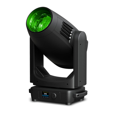
Description of the device
Overview
Installation instructions
Installation method via clamp
DMX-512 control connection
DMX-512 connection with DMX terminator
Led Moving Head DMX starting address selection
Control Board
Menu
DMX chart
Error message
Cleaning and maintenance
Technical specifications
Warranty
4
4
5
5
5
6
6
7
7
7
7
8
14
16
16
16
17
Sommaire
Introduction
Instructions de sécurité
Conditions d’utilisation
Présentation
Description
Instructions d’installation
Méthode d’installation avec des crochets
Connexion DMX 512
Connexion DMX 512 avec bouchon de terminaison
Réglage de l’adresse DMX du projecteur
Panneau de contrôle
Menu
Charte DMX
Entretien et maintenance
Spécifications techniques
Garantie
18
18
19
20
20
21
21
22
22
22
22
24
30
32
32
33

4USER MANUAL
ENGLISH |
Introduction
Thank you for your patronage. We are confident that our
excellent products and service can satisfy you. For your own
safety, please read this user manual carefully before installing
the device.
In order to install, operate, and maintain the lighting safety and
correctly. We suggest that the installation and operation should
be done by the verified technician and follow the instruction
strictly.
CAUTION !
Unplug mains lead before opening the housing.
Every person involved with the installation, operation and
maintenance of this device has to:
be qualified
follow carefully the instructions of this manual
Thank you for having chosen this professional LED Moving Head
projector.
You will see you have acquired a powerful and versatile device.
Unpack the device. Inside the box you should find :
1. One XLR connection cable
2. Two omega clamps
3. One safety rope
4. Manual
Please check carefully that there is no damage caused by
transportation. Should there be any, consult your dealer and
don’t install this device.
Safety instructions
Avant toute installation et utilisation du projecteur WILDSUN 200
S, veuillez lire attentivement les instructions de sécurité et les
précautions d’utilisation mentionnées ci-dessous.
CAUTION !
Be careful with your operations. With a dangerous voltage
you can suffer a dangerous electric shock when
touching wires.
This device has left the factory in perfect condition. In order
to maintain this condition and to ensure a safe operation, it is
absolutely necessary for the user to follow the safety instructions
and warning notes written in this user manual.
Important :
Damages caused by the disregard of this user manual are not
subject to warranty. The dealer will not accept liability for any
resulting defects or problems.
If the device has been exposed to temperature changes due
to environmental changes, do not switch it on immediately.
The arising condensation could damage the device. Leave the
device switched off until it has reached room temperature.
This device falls under protection-class I. Therefore it is essential
that the device should be earthed.
The electric connection must carry out by qualified person.
No move at operating mode.
If the external flexible cable or cord of this luminaire is damaged,
it shall be exclusively replaced by the manufacturer or his service
agent or a similar qualified person in order to avoid a hazard.
Make sure that the available voltage is not higher than stated at
the end of this manual.
Make sure the power cord is never crimped or damaged by
sharp edges. If this would be the case, replacement of the cable
must be done by an authorized dealer.
Always disconnect from the mains, when the device is not in use
or before cleaning it. Only handle the power cord by the plug.
Never pull out the plug by tugging the power cord.
Fixtures cannot be installed on combustible substances, keep
more than 50cm distance with wall for smooth air flow, so there
should be no shelter for fans and ventilation for heat radiation.
CAUTION !
PROJECTOR USING CLASS 2 LED SOURCES
(EN60625-1 : 1994)
This device uses multiple high-power (CLASS 2)
LED
(Light Emitting Diode) light sources.
Never look directly at the light source when it is lit; never stand
directly in the device’s beam close up.
Always ensure the power is disconnected when installing,
dismantling or replacing the device to prevent any risk of glare
and to avoid any harm to your eyes.
CAUTION !
Never touch the device during operation !
The housing may heat up.
CAUTION !
Never look directly into the light source, as sensitive
persons may suffer an epileptic shock.
Please be aware that damages caused by manual modifications
to the device are not subject to warranty. Keep away from
children and non-professionals.
INTRODUCTION | SAFETY INSTRUCTIONS

5
USER MANUAL
| ENGLISH
General guidelines
This device is a lighting effect for professional use on stages,
in discotheques, theatres, etc., the device was designed for
indoor use only.
The Wildsun 200S is IP20.
This fixture is only allowed to be operated with the max
alternating current which stated in the technical specifications
of this manual.
Lighting effects are not designed for permanent operation.
Consistent operation breaks may ensure that the device will
serve you for a long time without defects.
Do not shake the device. Avoid brute force when installing or
operating the device.
While choosing the installation-spot, please make sure that the
device is not exposed to extreme heat, moisture or dust. Please
don’t project the beam onto combustible substances. The
minimum distance between light-output from the Led Moving
Head and the illuminated surface must be more than 0.5 meter.
If you use the quick lock cam in hanging up the fixture, please
make sure the quick lock fasteners turned in the quick lock holes
correctly.
Operate the device only after having familiarized with its functions.
Do not permit operation by persons not qualified for operating
the device. Most damages are the result of unprofessional
operation.
Please use the original packaging if the device is to be
transported.
For safety reasons, please be aware that all modifications on the
device are forbidden.
If this device will be operated in any way different to the one
described in this manual, the product may suffer damages and
the guarantee becomes void. Furthermore, any other operation
may lead to short-circuit, burns, electric shock, lamp explosion,
crash, etc.
Description of the device
12 x 15W high power four-colors LEDs (Red / Green / Blue
/ White) individually controlable
3 DMX Channel modes: 17, 19, 60 DMX channels selectable
for numerous applications
Pan movement: pan 540°/630°, Tilt movement: tilt 265°
Strobe-effect with 1 to 25 flashes per second
Zoom: 8° to 32° linear zoom
General dimming and blackout for all four effect
Excellent RGBW mixing and rainbow effect
Control board with full color LCD graphic display and touch-
keyboard
Rechargeable back-up Battery for Display, no need external
power supply, enable users to enter display menu for address
setting or access other functions setting.
Software-upload by optional accessory via DMX line
Preset program: 7 built in programs can be called up via
DMX controller
Overview
1. Lens 7. RIGHT-button
2. Display 8. MODE/ESC-button
3. DSP Switch 9. UP-button
4. Microphone 10. ENTER-button
5. LEFT-Button 11. Handle
6. DOWN-button
GENERAL GUIDELINES | DESCRIPTION OF THE DEVICE | OVERVIEW

6USER MANUAL
ENGLISH |
12. Powercon socket 16. 3-Pin DMX in
13. Power Switch 17. 5-Pin DMX out
14. Fuse 18. 5-Pin DMX in
15. 3-Pin DMX out
Installation instructions
CAUTION !
Please consider the GB7000.15/EN60598-2-17
and the other respective national norms during the
installation. The installation must only be carried out by a
qualified person.
The applicable temperature for the Led Moving Head is between
0°C to 40°C. Do not use the Led Moving Head under or above
the temperature.
The installation of the effect has to be built and constructed in a
way that it can hold 10 times the weight for 1 hour without any
harming deformation.
The installation must always be secured with a secondary safety
attachment, e.g. an appropriate safety rope.
Never stand directly below the device when mounting, removing
or servicing the fixture.
The operator has to make sure the safety relating and machine
technical installations are approved by an expert before taking
the device into operation for the first time.
These installations have to be approved by a skilled person once
a year.
CAUTION !
Before taking into operation for the first time, the installation
has to be approved by an expert.
Cautions :
The effect should be installed outside areas where persons may
reach it, walk by or be seated.
Overhead mounting requires extensive experience, including
amongst others calculating working load limits, installation material
being used, and periodic safety inspection of all installation
material and the device. If you lack these qualifications, do not
attempt the installation yourself. Improper installation can result
in bodily injury.
CAUTION !
The electric connection must only be carried
out by a qualified electrician.
Before mounting make sure that the installation area can hold a
minimum point load of 10 times the device’s weight.
Connect the fixture to the mains with the power plug.
Installation method via clamp
Please refer to the picture below:
Fix the clamp on the bracket by tighten up the M12 screw on
the bracket to the M13 hole in the middle of the bracket.
Insert the quick-lock fasteners of the first Omega holder into the
respective holes on the bottom of the device. Tighten the quick-
lock fasteners fully clockwise.
Install the second Omega holder.
Pull the safety-rope through the holes on the bottom of the
base and over the trussing system or a safe fixation spot. Insert
the end in the carabiner and tighten the safety screw.
INSTALLATION INSTRUCTIONS

7
USER MANUAL
| ENGLISH
DMX-512 control connection
Connect the provided XLR cable to the female 3-pin or5-pin XLR
output of your controller and the other side to the male 3-pin
or5-pin XLR input of the moving head. You can chain multiple
Moving Head together through serial linking. The cable needed
should be two core, screened cable with XLR input and output
connectors. Please refer to the following diagram.
Adress 1 Adress 5 Adress 9
DMX-512 connection with DMX
terminator
For installations where the DMX cable has to run a long
distance or is in an electrically noisy environment, such as in
a discotheque, it is recommended to use a DMX terminator.
This helps in preventing corruption of the digital control signal by
electrical noise. The DMX terminator is simply an XLR plug with
a 120 Ohms resistor connected between pins 2 and 3, which is
then plugged into the output XLR socket of the last fixture in the
chain. Please see illustrations below.
Led Moving Head DMX starting
address selection
All fixtures should be given a DMX starting address when using
a DMX signal, so that the correct fixture responds to the correct
control signals. This digital starting address is the channel
number from which the fixture starts to “listen” to the digital control
information sent out from the DMX controller. The allocation of
this starting address is achieved by setting the correct number
on the display located on the base of the device.
You can set the same starting address for all fixtures or a group
of fixtures, or make different address for each fixture individually.
If you set the same address, all the units will start to “listen” to
the same control signal from the same channel number. In other
words, changing the settings of one channel will affect all the
fixtures simultaneously.
If you set a different address, each unit will start to “listen” to the
channel number you have set, based on the quantity of control
channels of the unit. That means changing the settings of one
channel will affect only the selected fixture.
In the case of the Moving head, which is a 24 channel fixture,
you should set the starting address of the first unit to 1, the
second unit to 25 (24 + 1), the third unit to 49 (24+ 25), and
so on.
Control Board
The Control Board offers several features: you can simply set
the starting address , run the pre-programmed program or make
a reset.
The main menu is accessed by pressing the button until the
display starts flashing.
Browse through the menu by pressing the button,
button, button or button. Press the Enter-button in
order to select the desired menu. You can change the selection
by pressing the the button, button, button or
button.
Confirm every selection by pressing the button. You can
leave every mode by pressing the button. The functions
provided are described in the following sections. it will exit from
flash 10 seconds after the last keypress. Press this key under
edit mode. The functions provided are described in the following
sections.
To access the display menu via the internal battery, press the
DSP button for 2 seconds; To shut off the display immediately,
choose the commend « Reset All» menu and press «Enter»
button, otherwise, the display will automatically switch off
about 1 minute from last button press.
INSTALLATION INSTRUCTIONS

8USER MANUAL
ENGLISH |
Menu
Address
Set Dmx
Addr
A001~AXXX DMX address setting
Function Mode
Set Dmx Address
Value Display
Set To Slave
Auto Program
Music Control
A001~AXXX
PAN…
Slave1,Slave2,Slave3
Master / Alone
Master / Alone
DMX address setting
DMX value display
Slave setting
Auto program
Music control
Users Mode
User Mode Stand Mode
Basic Mode
Extend Mode
User Mode A
User Mode B
User Mode C
User’s mode to change
channel numbers
Edit User Max channel
PAN :
Preset User modes
Options
Status Addr via DMX
No DMX Mode
Pan Reverse
Tilt Reverse
Pan Degree
Feedback
Pan/Tilt Spd
Zoom Speed
Mic Sens.
Hibernation
ON/OFF
Close/Hold/Auto/Music
ON/OFF
ON/OFF
630/540
ON/OFF
Speed 1~ 4
Speed 1~ 2
0~99%
OFF, 01M~99M,15M
Add. via DMX
Auto run if no DMX
Pan Reverse movement
Tilt Reverse movement
Pan Degree Select
Movement Feedback
switch
Movement Mode Select
Zoom Speed
Sensitivity of Mic.
Standby mode
Service PIN Service PIN
RDM PID
Password=XXX
xxxxxx
Service Code“=050”
RDM PID Code
Fans Control Head Control 75%
High
Low
Head Fans Speed Mode
Select
Base Control 10%
30%
50%
Base Fans Speed Mode
Select
Disp.Setting Shutoff Time
Flip Display
Key Lock
DispFlash
02~60m 05m
ON/OFF
ON/OFF
ON/OFF
Display shutoff time
Display Reverse 180
degree
Key Lock
Disp Flash if no DMX
Initial Pos. PAN =XXX Initial effect position
Trigger DMX Value Disp.
Set To Slave
Auto Program
Music Ctrl.
PAN……
Slave1,Slave2,Slave3
Master / Alone
Master / Alone
DMX value display
Slave setting
Auto program
Music control
Reset Default ON/OFF Restore factory sett.
Info
Time Info. Current Time
Ttl Life Hrs
Last Run Hrs
Timer PIN
Clr Last Run
XXXX(Hours)
XXXX(Hours)
XXXX(Hours)
Password=XXX
ON/OFF
Software Ver V1.0…… Software version of each IC
Test
Home All
Pan&Tilt
Zoom
Reset all motors
Reset Pan&Tilt
Reset Zoom
Test Channel PAN …… Test function
Manual Ctrl. PAN =XXX
:
Fine adjustment of the lamp
Calibration --Password--
PAN
:
Calbrate and adjust the
effects to standard/right
position Password “050”
Preset
Select Prog. Prog. Part 1 = Program 1 ~ 10 Program 1
Prog. Part 2 = Program 1 ~ 10 Program 2
Prog. Part 3 = Program 1 ~ 10 Program 3
Select programs to be run
Edit Prog. Program 1
:
Program 10
Program Test
Step 01=SCxxx
Step 64=SCxxx
Testing program
Program in loop
Save and exit
Edit Scenes Edit Scene 001
~ Edit Scene 128
Pan,Tilt,……
--Fade Time--
--Secne Time--
Input By Outside
Save and automatically
return
manual scenes edit
Scenes Input XX~XX Automat. scenes rec
Function mode
Set DMX Address
With this function, you can adjust the desired DMX-address via
the Control Board.
1. Access the main menu.
2. Tap the <Up/Down> button until “Set DMX Address” is
displayed.
3. Press ENTER, the display will show “Set DMX Address”.
4. Tap the <Up/Down> button, the display will show
“A001~AXXX”
5. Press ENTER to confirm or press <MODE/ESC> to return
to the main menu.
Value Display
With this function you can display the DMX 512 value of each
channel. The display automatically shows the channel with a
value changing.
1. Access the main menu.
2. Tap the <Up/Down> button until “Value Display” is displayed.
3. Press ENTER, the display will show “Value Display”.
4. Tap the <Up/Down> button, choose each channel.
5. Press ENTER to confirm or press <MODE/ESC> to return
to the main menu.
Set to slave
With this function, you can define the device as slave.
1. Access the main menu.
2. Tap the <Up/Down> button until “Set To Slave” is displayed.
3. Press ENTER, the display will show “Set To Slave”.
4. Tap the <Up/Down> button, the display will show “Slave1”,
”Slave2”, ”Slave3”.
5. Press ENTER to confirm or press <MODE/ESC> to return
to the main menu.
Auto Program
With this function, you can run the internal program. You can
select the desired program under “Select program”. You can
set the number of steps under “Edit program”. You can edit the
individual scenes under “Edit scenes”. With this function, you
can run the individual scenes either automatically, i.e. with the
adjusted Step-Time.
1. Access the main menu.
2. Tap the <Up/Down> button until “Auto Program” is
displayed.
3. Press ENTER, the display will show “Auto Program”.
4. Tap the <Up/Down> button, the display will show “Master1”,
” Alone”.
5. Press ENTER to confirm or press <MODE/ESC> to return
to the main menu.
Music control
With this function, you can run the internal program sound-
controlled.
1. Access the main menu.
2. Tap the <Up/Down> button until “Music control” is displayed.
3. Press <ENTER>, the display will show “Music control”.
4. Tap the <Up/Down>button, the display will show “Master1”,
” Alone”.
5. Press <ENTER> to confirm or press <MODE/ESC> to
MENU

9
USER MANUAL
| ENGLISH
return to the main menu.
Information
Time information
Current Time
With this function, you can display the temporary running time of
the device from the last power on. The display shows “XXXX”,
“XXXX” stands for the number of hours. The counter is resetted
after turning the device off.
1. Tap <MODE/ESC>button, access the main menu, Tap
the <Up/Down> button until “Information” is displayed. Press
ENTER, the display will show “Information”. Tap the <Up/
Down> button until the display will show “Timer Password”.
Press ENTER, the display will show “Timer Password”.
2. Press <Up/Down>, the display will show “Current Time”.
3. Press <ENTER>, the display will show “Current Time”.
4. The display will show “XXXX” (Hours);
5. Press <ENTER> to confirm or press <MODE/ESC> to
return to the main menu.
Total Life Hours
With this function, you can display the running time of the device.
The display shows “XXXX”, “XXXX” stands for the number of
hours.
1. Tap <MODE/ESC> button, access the main menu, Tap
the <Up/Down> button until “Information” is displayed. Press
ENTER, the display will show “Information”. Tap the <Up/
Down> button until the display will show “Timer Password”.
Press ENTER, the display will show “Timer Password”.
2. Press <Up/Down>, the display will show “Total Life Hours”.
3. Press< ENTER>, the display will show “Total Life Hours”.
4. The display will show “XXXX” (Hours);
5. Press <ENTER> to confirm or press <MODE/ESC> to
return to the main menu.
Last Run Hours
With this function, you can display the last running time of the
fixture since the last reset. The display shows “XXXX”, “XXXX”
stands for the number of hours.
1. Tap <MODE/ESC> button, access the main menu, Tap
the <Up/Down> button until “Information” is displayed. Press
ENTER, the display will show “Information”. Tap the <Up/
Down> button until the display will show “Timer Password”.
Press ENTER, the display will show “Timer Password”.
2. Press <Up/Down>, the display will show “Last Run Hours”.
3. Press < ENTER>, the display will show “Last Run Hours”.
4. The display will show “XXXX” (Hours);
5. Press <ENTER> to confirm or press <MODE/ESC> to
return to the main menu.
Timer Password
With this function, you can display the timer password.
1. Tap <MODE/ESC> button, access the main menu, Tap
the <Up/Down> button until “Information” is displayed. Press
ENTER, the display will show “Information”. Tap the <Up/
Down> button until the display will show “Timer Password”.
Press ENTER, the display will show “Timer Password”.
2. Press <Up/Down>, the display will show “Timer Password”.
3. Press < ENTER>, the display will show “Timer Password”.
The time password is 038.
4. Press <ENTER> to confirm or press <MODE/ESC> to
return to the main menu.
Clear Last Run
With this function, you can clear last run time of the fixture. The
display shows “ON” or “OFF”, Press “Enter” to confirm.
1. Tap <MODE/ESC> button, access the main menu, Tap
the <Up/Down> button until “Information” is displayed. Press
ENTER, the display will show “Information”. Tap the <Up/
Down> button until the display will show “Timer Password”.
Press ENTER, the display will show “Timer Password”.
2. Press <Up/Down>, the display will show “Clear Last Run”.
3. At “L-Timer Password” menu input right password, Press <
ENTER>, the display will show “Clear Last Run”.
4. The display show “OFF”,Press <Up/Down>, the display will
show “ON”.
5. Press <ENTER> to confirm or press <MODE/ESC> to
return to the main menu.
Temperature Info
Head Temperature
With this function you can display the current temperature of the
head of the fixture.
1. Tap <MODE/ESC> button, access the main menu, Tap
the <Up/Down> button until “Information” is displayed. Press
ENTER, the display will show “Information”. Tap the <Up/
Down> button until “Temperature Info” is displayed. Press
ENTER, the display will show “Temperature Info”.
2. Press <Up/Down>, the display will show “Head
Temperature”.
3. Press <ENTER>, the display will show “Head Temperature”.
4. The display show “XXX °C / °F”.
5. Press <ENTER> to confirm or press <MODE/ESC> to
return to the main menu.
Software version
With this function, you can display the software version of the
device.
1. Tap <MODE/ESC> button, access the main menu, Tap
the <Up/Down> button until “Information” is displayed. Press
ENTER, the display will show “Information”.
2. Press <Up/Down>, the display will show “Software version”.
3. Press <ENTER>, the display will show “Software version”.
4. The display show “Ver 1.0……”.
5. Press <ENTER> to confirm or press <MODE/ESC> to
return to the main menu.
Personality
Status setting
Address via DMX
With this function, you can adjust the desired DMX-address via
an external controller.
1. Tap <MODE/ESC> button, access the main menu, Tap the
MENU

10 USER MANUAL
ENGLISH | MENU
<Up/Down> button until “Personality” is displayed.
Press ENTER, the display will show “Personality”. Tap the
<Up/Down> button until the display will show “Status setting”.
Press ENTER, the display will show “Status setting”.
2. Press <Up/Down>, the display will show “Address via
DMX”.
3. Press <ENTER>, the display will show “Address via DMX”.
4. The display show “ON”, Press <Up/Down>, the display will
show “OFF”.
5. Press <ENTER> to confirm or press <MODE/ESC> to
return to the main menu.
No DMX Status
With this function, when the drive is not DMX signal, it runs
automatism, close, hold and music, the default is hold.
1. Tap <MODE/ESC> button, access the main menu, Tap
the <Up/Down button until “Personality” is displayed. Press
ENTER, the display will show “Personality”. Tap the <Up/
Down> button until the display will show “Status setting”.
Press <ENTER>, the display will show “Status setting”.
2. Press <Up/Down>, the display will show “No DMX Status”.
3. Press <ENTER>, the display will show “No DMX Status”.
4. The display show “Hold”, Press <Up/Down>, the display
will show “Close”, “Auto”, “Music”.
5. Press <ENTER> to confirm or press <MODE/ESC> to
return to the main menu.
Pan Reverse
With this function you can reverse the Pan-movement.
1. Tap <MODE/ESC> button, access the main menu, Tap
the <Up/Down> button until “Personality” is displayed. Press
ENTER, the display will show “Personality”. Tap the <Up/
Down> button until the display will show “Status setting”.
Press <ENTER>, the display will show “Status setting”.
2. Press <Up/Down>, the display will show “Pan Reverse”.
3. Press <ENTER>, the display will show “Pan Reverse”.
4. The display show “OFF”, Press <Up/Down>, the display
will show “ON”.
5. Press <ENTER> to confirm or press <MODE/ESC> to
return to the main menu.
Tilt Reverse
With this function you can reverse the Tilt-movement.
1. Tap <MODE/ESC> button, access the main menu, Tap
the <Up/Down> button until “Personality” is displayed. Press
ENTER, the display will show “Personality”. Tap the <Up/
Down> button until the display will show “Status setting”.
Press <ENTER>, the display will show “Status setting”.
2. Press <Up/Down>, the display will show “Tilt Reverse”.
3. Press <ENTER>, the display will show “Tilt Reverse”.
4. The display show “OFF”, Press <Up/Down>, the display
will show “ON”.
5. Press <ENTER> to confirm or press <MODE/ESC> to
return to the main menu.
Pan Degree
With this function, you can select pan degree for 630 or 540.
1. Tap <MODE/ESC> button, access the main menu, Tap the
<Up/Down> button until “Personality” is displayed.
Press ENTER, the display will show “Personality”. Tap the
<Up/Down> button until the display will show “Status setting”.
Press ENTER, the display will show “Status setting”.
2. Press <Up/Down>, the display will show “Pan Degree”.
3. Press <ENTER>, the display will show “Pan Degree”.
4. The display show “540”, Press <Up/Down>, the display will
show “630”.
5. Press <ENTER> to confirm or press <MODE/ESC> to
return to the main menu.
Feedback
With this function, you can feedback switch of pan movement
or tilt movement.
1. Tap <MODE/ESC> button, access the main menu, Tap the
<Up/Down> button until “Personality” is displayed.
Press ENTER, the display will show “Personality”. Tap the
<Up/Down> button until the display will show “Status setting”.
Press ENTER, the display will show “Status setting”.
2. Press <Up/Down>, the display will show “Feedback”.
3. Press <ENTER>, the display will show “Feedback”.
4. The display show “ON”, Press <Up/Down>, the display will
show “OFF”.
5. Press <ENTER> to confirm or press <MODE/ESC> to
return to the main menu.
Movement Speed
With this function, you can select scan mode from 1 to 4.
1. Tap <MODE/ESC> button, access the main menu, Tap the
<Up/Down> button until “Personality” is displayed.
Press ENTER, the display will show “Personality”. Tap the
<Up/Down> button until the display will show “Status setting”.
Press ENTER, the display will show “Status setting”.
2. Press <Up/Down>, the display will show “Movement
Speed”.
3. Press <ENTER>, the display will show “Movement Speed”.
4. The display show “Speed 1”, Press <Up/Down>, the
display will show “Speed 2”, “Speed 3”, “Speed 4”.
5. Press <ENTER> to confirm or press <MODE/ESC> to
return to the main menu.
Zoom Speed
With this function, you can select Zoom Speed between “Speed
1” and “Speed 2”. “Speed 2” is the faster setting.
1. Tap <MODE/ESC> button, access the main menu, Tap the
<Up/Down> button until “Personality” is displayed.
Press ENTER, the display will show “Personality”. Tap the
<Up/Down> button until the display will show “Status setting”.
Press ENTER, the display will show “Status setting”.
2. Press <Up/Down>, the display will show “Zoom Speed”.
3. Press <ENTER>, the display will show “Zoom Speed”.
4. The display show “Speed 1”, Press <Up/Down>, the
display will show “Speed 2”.
5. Press <ENTER> to confirm or press <MODE/ESC> to
return to the main menu.
Mic Sensitivity
With this function, the default is 70%, you can select the desired
microphone sensitivity from 0 % to 99 %.
1. Tap <MODE/ESC> button, access the main menu, Tap
the <Up/Down> button until “Personality” is displayed. Press
ENTER, the display will show “Personality”. Tap the <Up/
Down> button until the display will show “Status setting”.

11
USER MANUAL
| ENGLISH
MENU
Press ENTER, the display will show “Status setting”.
2. Press <Up/Down>, the display will show “Mic Sensitivity”.
3. Press <ENTER>, the display will show “Mic Sensitivity”.
4. The display show “70%”, Press <Up/Down>, the display
will show “0~99%”.
5. Press <ENTER> to confirm or press <MODE/ESC> to
return to the main menu.
Hibernation - Standby mode
The step motors will be power off if the fixture stay without DMX
signal for 15 mins (Factory default). And the fixture will be reset
before working once it receive DMX signal again.
1. Tap <MODE/ESC> button, access the main menu, Tap
the <Up/Down> button until Personality” is displayed. Press
ENTER, the display will show “Personality”. Tap the <Up/
Down> button until the display will show “Status setting”.
Press ENTER, the display will show “Status setting”.
2. Press <Up/Down>, the display will show “Hibernation”.
3. Press <ENTER>, the display will show “Hibernation”.
4. The display show “15M”, Press <Up/Down>, the display
will show “01M”, “02M” …. “99M” or“OFF”.
5. Press <ENTER> to confirm or press <MODE/ESC> to
return to the main menu.
Fans Control
Head Control
With this function, you can set the speed of the running head
fans. The selections have Auto, high and low.
1. Tap <MODE/ESC> button, access the main menu, Tap
the <Up/Down> button until “Personality” is displayed. Press
ENTER, the display will show “Personality”. Tap the <Up/
Down> button until the display will show “Fans Control”. Press
ENTER, the display will show “Fans Control”.
2. Press <Up/Down>, the display will show “Head Control”.
3. Press <ENTER>, the display will show “Head Control”.
4. The display show “Auto Fans Speed”, Press <Up/Down>,
the display will show “High Fans Speed”, “Low Fans Speed”.
5. Press <ENTER> to confirm or press <MODE/ESC> to
return to the main menu.
Base Control
With this function, you can set the speed of the running base
fans. The selections have 10%, 30% and 50%.
1. Tap <MODE/ESC> button, access the main menu, Tap
the <Up/Down> button until “Personality” is displayed. Press
ENTER, the display will show “Personality”. Tap the <Up/Down>
button until the display will show “Fans Control”. Press ENTER,
the display will show “Fans Control”.
2. Press <Up/Down>, the display will show “Base Control”.
3. Press <ENTER>, the display will show “Base Control”.
4. The display show “30%”, Press <Up/Down>, the display will
show “10%”, “50%”.
5. Press <ENTER> to confirm or press <MODE/ESC> to return
to the main menu.
Display settings
Shut off time
With this function you can shut off the color LCD display after 2
to 59 minutes. Turn the encoder in order to select the desired
shut off time. The default is 5 minute.
Display Reverse
With this function you can the entire display to be flipped by 180˚
to allow for better view when the fixture is hung from truss or a
ceiling. This function is disabled as default.
Key Lock
With this function you can activate the automatic keylock status.
If this function is activated, the keys will be locked automatically
after exiting the edit mode for 15 seconds. keeping press the
[MENU] key for 3seconds if you do not need this function.
1. Tap <MODE/ESC> button, access the main menu, Tap
the <Up/Down> button until “Personality” is displayed. Press
ENTER, the display will show “Personality”.
2. Press <Up/Down>, the display will show “Display Setting”.
3. Press <ENTER>, the display will show “Display Setting”.
4. The display show “Shutoff Time”, Press <Up/Down>, the
display will show “Display Reverse”, “Key Lock”.
5. Press <ENTER> to confirm or press <MODE/ESC> to
return to the main menu.
Temperature C/F
With this function, Display the temperature for Celsius or
Fahrenheit.
1. Tap <MODE/ESC> button, access the main menu, Tap
the <Up/Down> button until “Personality” is displayed. Press
ENTER, the display will show “Personality”.
2. Press <Up/Down>, the display will show “Temperature
C/F”.
3. Press< ENTER>, the display will show “Temperature C/F”.
4. The display show “Fahrenheit”, Press <Up/Down>, the
display will show “Celsius”.
5. Press <ENTER> to confirm or press <MODE/ESC> to
return to the main menu.
Initial effect
With this function, Display initial effect position.
1. Tap <MODE/ESC> button, access the main menu, Tap
the <Up/Down> button until “Personality” is displayed. Press
ENTER, the display will show “Personality”.
2. Press <Up/Down>, the display will show “Initial effect”.
3. Press <ENTER>, the display will show “Initial effect”.
4. The display show “XXX”.
5. Press <ENTER> to confirm or press <MODE/ESC> to
return to the main menu.
Restore Default
With this function, you can select restore factory set for ON or
OFF, the default is OFF.
1. Tap <MODE/ESC> button, access the main menu, Tap
the <Up/Down> button until “Personality” is displayed. Press
ENTER, the display will show “Personality”.
2. Press <Up/Down>, the display will show “Restore Default”.
3. Press <ENTER>, the display will show “Restore Default”.
4. The display show “OFF”, Press <Up/Down>, the display
will show “ON”.
5. Press <ENTER> to confirm or press <MODE/ESC> to
return to the main menu.

12 USER MANUAL
ENGLISH |
Reset-functions
With this function you can reset the device via the Control
Board. You can select the different reset functions by turning
the encoder.
1. Tap <MODE/ESC> button, access the main menu, Tap the
<Up/Down> button until “Reset-functions” is displayed. Press
ENTER, the display will show “Reset-functions”.
2. The display show “Reset All”, Press <Up/Down>, the
display will show “Reset All”, “Reset Pan/Tilt”, “Reset ZOOM”.
3. Press <ENTER> to confirm or press <MODE/ESC> to
return to the main menu.
Effect Adjust
Test channel
With this function you can test each channel on its (correct)
function.
1. Tap <MODE/ESC> button, access the main menu, Tap the
<Up/Down> button until “Effect Adjust” is displayed. Press
ENTER, the display will show “Effect Adjust”.
2. Press <Up/Down>, the display will show “Test Channel”.
3. Press <ENTER>, the display will show “Test Channel”.
4. The display show “Pan Moving” first channel, Press <Up/
Down>, can choose other channel.
5. Press <ENTER> to confirm or press <MODE/ESC> to
return to the main menu.
Manual control
With this function, you can control the light sources more easily.
All effects will be canceled, the shutter opens and the dimmer
intensity will be set to 100 %.
1. Tap <MODE/ESC> button, access the main menu, Tap the
<Up/Down> button until “Effect Adjust” is displayed. Press
ENTER, the display will show “Effect Adjust”.
2. Press <Up/Down>, the display will show “Manual control”.
3. Press <ENTER>, the display will show “Manual control”.
4. The display show “PAN=XXX”.
5. Press <ENTER> to confirm or press <MODE/ESC> to
return to the main menu.
Calibrate values
With this function, you can calibrate and adjust the effect wheels
to their correct positions. The password of calibrate values is
050.
1. Tap <MODE/ESC> button, access the main menu, Tap the
<Up/Down> button until “Effect Adjust” is displayed. Press
ENTER, the display will show “Effect Adjust”.
2. Press <Up/Down>, the display will show “Calibrate values”.
3. Press <ENTER>, the display will show “Calibrate values”.
4. The display show “Password=XXXX”.
5. Press <ENTER> to confirm or press <MODE/ESC> to
return to the main menu.
Users mode set
In this menu, user can select different channels list by different
sequence:
For example, after the user enter this manual, if select Auto
Program = CH 22, means in this User’s mode, the “Dimmer” is
in Channel 16.
User mode
With this function, you can create user defined channel orders.
Preset User mode
With this function, you can adjust the rest user defined channel
order.
1. Tap <MODE/ESC> button, access the main menu, Tap the
<Up/Down> button until “Users mode set” is displayed. Press
ENTER, the display will show “Users mode set”.
2. The display show “User Mode” first channel, Press <Up/
Down> the display will show “Edit User Mode”.
3. Press <ENTER> to confirm or press <MODE/ESC> to
return to the main menu.
Edit program
Select program
With this function, you can select the program for the Program
Run.
Edit program
With this function, you can edit the internal programs.
Edit scenes
With this function, you can edit the scenes of the internal
programs.
Rec. Controller
The moving head features an integrated DMX-recorder by which
you can transmit the programmed scenes from your DMX-
controller to the moving head. Adjust the desired scene numbers
via the encoder (from – to). When you call up the scenes at your
controller, they will automatically be transmitted to the moving
head.
Excursion
A Master unit can send up to 3 different data groups to the Slave
units, i.e. a Master unit can start 3 different Slave units, which
run 3 different programs. The Master unit sends the 3 program
parts in a continuous loop.
Auto Pro
Part 1
Auto Pro
Part 2
Auto Pro
Part 3
Auto Pro
Part 1
Auto Pro
Part 2
Auto Pro
Part 3
Auto Pro
Part 1
Auto Pro
Part 2
Auto Pro
Part 3
The Slave unit receives data from the Master unit according to
the group which the Slave unit was assigned to. If e.g. a Slave
unit is set to “Slave 1” in the menu “Set to Slave”, the Master unit
sends “Auto Program Part 1” to the Slave unit. If set to “Slave 2”,
the Slave unit receives “Auto Program Part 2”.
To start a Auto Program please proceed as follows:
1. Slave-Setting
Select “Function Mode” by turning the encoder.
Press the Enter button to confirm.
Select “Set to slave” by turning the encoder.
Press the Enter button to confirm.
Turn the encoder to select “Slave 1”, “Slave 2” or
“Slave 3”.
MENU

13
USER MANUAL
| ENGLISH
Press the Enter button to confirm.
Press the MODE/ESC button in order to return to the main
menu.
2. Automatic Program Run
Select “Function Mode” by turning the encoder.
Press the Enter button to confirm.
Select “Auto Program” by turning the encoder.
Press the Enter button to confirm.
Turn the encoder to select “Master” or “Alone”. The selection
«Alone» means Stand Alone-mode and «Master» that the
device is defined as master.
Press the Enter button to confirm.
Press the MODE/ESC button in order to return to the main
menu.
3. Program selection for Auto Pro Part
Select “Edit program” by turning the encoder.
Press the Enter button to confirm.
Select “Select programs” by turning the encoder.
Press the Enter button to confirm.
Turn the encoder to select “Auto Pro Part 1”, “Auto Pro Part
2” or “Auto Pro Part 3”, and thus select which Slave program
is to be sent. Selection “Part 1” means, that the Slave unit runs
the same program as the master units.
Press the Enter button to confirm.
Press the MODE/ESC button in order to return to the main
menu.
4. Program selection for Edit Program
• Select “Edit program” by turning the encoder.
• Press the Enter button to conrm.
• Select “Edit program” by turning the encoder.
• Press the Enter button to conrm.
• Turn the encoder to select the desired program. With this
function you can edit specific scenes into a specific program.
• Press the Enter button to conrm.
• Press the MODE/ESC button in order to return to the main
menu.
5. Automatic Scene Recording
Select “Edit program” by turning the encoder.
Press the Enter button to confirm.
Select “Edit scenes” by turning the encoder.
Turn the encoder to select the desired scene numbers. You
can program a maximum number of 250 • Turn the encoder
to select the desired scene numbers. You can program a
maximum number of 250 scenes.
Press the Enter button to confirm.
Press the MODE/ESC button in order to return to the main
menu.
Example:
Program 2 includes scenes: 10, 11, 12, 13
Program 4 includes scenes: 8, 9, 10
Program 6 includes scenes: 12, 13, 14, 15
Auto Pro Part 1 is Program 2
Auto Pro Part 2 is Program 3
Auto Pro Part 3 is Program 6
The 3 Slave groups run the Auto Program in certain time
segments, as shown in the following picture:
Part 1:
Scene 10 Scene 11 Scene 12 Scene 13
Part 2:
Scene 8S cene 9S cene 10 Scene 8
Part 3:
Scene 12 Scene 13 Scene 14 Scene 15
MENU

14 USER MANUAL
ENGLISH |
DMX chart
Fonction des canaux DMX et valeurs correspondantes
Mode/circuit Valeur Fonction
St Ba Ex
111 PAN Movement 8bit :
0-255 Pan Movement
2 2 Pan Fine 16bit
0-255 Fine control of Pan movement
323 TILT Movement 8bit :
0-255 Tilt Movement
4 4 Tilt Fine 16bit
0-255 Fine control of Tilt movement
535
Speed Pan/Tilt movement:
0-225 max to min speed
226-235 blackout by movement
236-255 no function
6 4 Red LED -all arrays :
0-255 Red ( 0-Black , 255-100% Red )
7 5 Green LED-all arrays :
0-255 Green ( 0-Black , 255-100% Green )
8 6 Blue LED -all arrays :
0-255 Blue ( 0-Black , 255-100% Blue )
9 7 White LED -all arrays :
0-255 White ( 0-Black , 255-100% White )
17 Red LED -array 1 :
0-255 Red ( 0-Black , 255-100% Red )
18 Green LED-array 1 :
0-255 Green ( 0-Black , 255-100% Green )
19 Blue LED -array 1 :
0-255 Blue ( 0-Black , 255-100% Blue )
20 White LED -array 1 :
0-255 White ( 0-Black , 255-100% White )
21 Red LED -array 2 :
0-255 Red ( 0-Black , 255-100% Red )
22 Green LED-array 2 :
0-255 Green ( 0-Black , 255-100% Green )
23 Blue LED -array 2 :
0-255 Blue ( 0-Black , 255-100% Blue )
24 White LED -array 2 :
0-255 White ( 0-Black , 255-100% White )
25 Red LED -array 3 :
0-255 Red ( 0-Black , 255-100% Red )
26 Green LED-array 3 :
0-255 Green ( 0-Black , 255-100% Green )
27 Blue LED -array 3 :
0-255 Blue ( 0-Black , 255-100% Blue )
28 White LED -array 3:
0-255 White ( 0-Black , 255-100% White )
29 Red LED -array 4 :
0-255 Red ( 0-Black , 255-100% Red )
30 Green LED-array 4 :
0-255 Green ( 0-Black , 255-100% Green )
31 Blue LED -array 4 :
0-255 Blue ( 0-Black , 255-100% Blue )
32 White LED -array 4 :
0-255 White ( 0-Black , 255-100% White )
33 Red LED -array5 :
0-255 Red ( 0-Black , 255-100% Red )
Fonction des canaux DMX et valeurs correspondantes
Mode/circuit Valeur Fonction
St Ba Ex
34 Green LED-array 5 :
0-255 Green ( 0-Black , 255-100% Green )
35 Blue LED -array 5 :
0-255 Blue ( 0-Black , 255-100% Blue )
36 White LED -array 5 :
0-255 White ( 0-Black , 255-100% White )
37 Red LED -array 6 :
0-255 Red ( 0-Black , 255-100% Red )
38 Green LED-array 6 :
0-255 Green ( 0-Black , 255-100% Green )
39 Blue LED -array6 :
0-255 Blue ( 0-Black , 255-100% Blue )
40 White LED -array 6 :
0-255 White ( 0-Black , 255-100% White )
41 Red LED -array 7 :
0-255 Red ( 0-Black , 255-100% Red )
42 Green LED-array 7 :
0-255 Green ( 0-Black , 255-100% Green )
43 Blue LED -array 7 :
0-255 Blue ( 0-Black , 255-100% Blue )
44 White LED -array 7 :
0-255 White ( 0-Black , 255-100% White )
45 Red LED -array 8 :
0-255 Red ( 0-Black , 255-100% Red )
46 Green LED-array 8 :
0-255 Green ( 0-Black , 255-100% Green )
47 Blue LED -array 8 :
0-255 Blue ( 0-Black , 255-100% Blue )
48 White LED -array 8:
0-255 White ( 0-Black , 255-100% White )
49 Red LED -array 9 :
0-255 Red ( 0-Black , 255-100% Red )
50 Green LED-array 9 :
0-255 Green ( 0-Black , 255-100% Green )
51 Blue LED -array 9 :
0-255 Blue ( 0-Black , 255-100% Blue )
52 White LED -array 9 :
0-255 White ( 0-Black , 255-100% White )
53 Red LED -array10 :
0-255 Red ( 0-Black , 255-100% Red )
54 Green LED-array 10 :
0-255 Green ( 0-Black , 255-100% Green )
55 Blue LED -array 10 :
0-255 Blue ( 0-Black , 255-100% Blue )
56 White LED -array 10 :
0-255 White ( 0-Black , 255-100% White )
57 Red LED -array 11 :
0-255 Red ( 0-Black , 255-100% Red )
58 Green LED-array 11 :
0-255 Green ( 0-Black , 255-100% Green )
59 Blue LED -array 11 :
0-255 Blue ( 0-Black , 255-100% Blue )
60 White LED -array 11 :
0-255 White ( 0-Black , 255-100% White )
DMX CHART

15
USER MANUAL
| ENGLISH
Fonction des canaux DMX et valeurs correspondantes
Mode/circuit Valeur Fonction
St Ba Ex
61 Red LED -array12 :
0-255 Red ( 0-Black , 255-100% Red )
62 Green LED-array 12 :
0-255 Green ( 0-Black , 255-100% Green )
63 Blue LED -array 12 :
0-255 Blue ( 0-Black , 255-100% Blue )
64 White LED -array 12 :
0-255 White ( 0-Black , 255-100% White )
10 8 6
Shutter, strobe:
0-15 Led trun on
16-249 Strobe effect slow to fast
250-255 Led turn on
11 9 7 Dimmer intensity:
0-255 Intensity 0 to 100%
12 10 8
Color Macro:
0-7 No function
8--255 Color Rainbow from slow to fast
Color Presets:
0-4 No function
5--9 White2700k
10--14 White3200k
15-19 White4300k
20-24 White5600k
25-29 White6500k
30-34 White8000k
35-39 Red
40-44 Green
45-49 Blue
50-54 Natural White
55-59 Full White
60-64 Yellow
13 11 9
65-69 Magenta
70-74 Cyan
75-79 Salmon
80-84 Turquoise
85-89 Light Green
90-94 Steel Blue
95-99 Orange
100-104 Straw
105-109 Pale Lavander
110-114 Pink
115-119 RED/WHITE
120-124 GREEN/WHITE
125-129 BLUE/WHITE
130-134 Yellow/WHITE
135-139 Cyan/WHITE
140-144 Magenta/WHITE
145-149 WHITE/Red
150--154 WHITE/Green
155-159 WHITE/Blue
160--164 WHITE/Yellow
165--169 WHITE/Cyan
170--174 WHITE/Magenta
175--179 Blue/Red
Fonction des canaux DMX et valeurs correspondantes
Mode/circuit Valeur Fonction
St Ba Ex
180--184 Blue/Green
185--189 Green/Red
190 --194 Red/Blue
195--199 Green/Blue
200--204 Red/Green
205-255 Reserved
14 12 10 Color Presets Dimmer:
0-255 Dimmer 0 to 100%
15 13 11
Chase Patterns:
0--9 Led trun off
10--19 Chase 1
20--29 Chase 2
30--39 Chase 3
40--49 Chase 4
50--59 Chase 5
60--69 Chase 6
70--79 Chase 7
80--89 Chase 8
90--99 Chase 9
100--109 Chase 10
110--119 Chase 11
120--129 Chase 12
130--139 Chase 13
140--149 Chase 14
150--159 Chase 15
160--169 Chase 16
170--179 Chase 17
180--189 Chase 18
190--199 Chase 19
200--219 Chase 20
210--219 Chase 21
220--255 Chase 22
16 14 12
Chase Speed:
0-125 Fast to Slow Backward
126-130 Stop(Speed=0)
131-255 Slow to Fast Forward
17 15 13 Chase Fade:
0-255 Fade Chase
18 16 14 Zoom :
0-255 Zoom adjustment from 11 to 45
15 Zoom Fine :
0-255 Fine control for Zoom adjustment
19 17 16
Reset, internal programs:
0-79 Normal
80-84 All motor reset
85-87 Scan motor reset
88-90 no function
91-93 no function
94-96 no function
97-99 Others motor reset
100-119 Internal program 1 (secne1~8 of EEPROM)
120-139 Internal program 2 (secne9~16 of EEPROM)
140-159 Internal program 3 (secne17~24 of EEPROM)
160-179 Internal program 4 (secne25~32 of EEPROM)
180-199 Internal program 5 (secne33~40 of EEPROM)
200-219 Internal program 6 (secne41~48 of EEPROM)
220-239 Internal program 7 (secne49~56 of EEPROM)
240-255 Music Control (secne of Program 1)
DMX CHART

16 USER MANUAL
ENGLISH |
Error message
When you turn on the fixture, it will make a reset at first. The
display may show “Err channel is XX” while there are problems
with one or more channels. “XX” stands for channel 1, 2, 3, 4,
5, 6 who has the testing sensor for positioning. For example,
when the display shows “Err channel is Pan movement”, it
means there is some error in channel 1. If there are some errors
on channel 1, channel 3, channel 23 at the same time, you
may see the error message “Err channel is Pan movement”, “Err
channel is Tilt movement”, “Err channel is Zoom” flash repeated
for 2 times, and then the fixture will generate a second reset.
If the fixture remain error message after performing reset more
than 2 times, only the channels which have errors can not work
properly, others can work as usual. Please contact with dealer or
manufacturer for service, self repair is not allowed.
PAN - movement Er
(PAN-head movement error) This message will appear after
the reset of the fixture if the head’s magnetic-indexing circuit
malfunctions (sensor failed or magnet missing) or the stepping-
motor is defective (or its driving IC on the main PCB). The TILT-
movement is not located in the default position after the reset.
TILT- movement Er
(TILT-head movement error) This message will appear after
the reset of the fixture if the head’s magnetic-indexing circuit
malfunctions (sensor failed or magnet missing) or the stepping-
motor is defective (or its driving IC on the main PCB). The TILT-
movement is not located in the default position after the reset.
Cleaning and maintenance
The following points have to be considered during the inspection:
All screws for installing the devices or parts of the device
have to be tightly connected and must not be corroded.
There must not be any deformations on the housing, color
lenses, fixations and installation spots (ceiling, suspension,
trussing).
Mechanically moved parts must not show any traces of
wearing and must not rotate with
unbalances.
The electric power supply cables must not show any
damage, material fatigue or sediments.
Further instructions depending on the installation spot and
usage have to be adhered by a skilled installer and any
safety problems have to be removed.
CAUTION !
Disconnect from mains before
starting maintenance operation
We recommend a frequent cleaning of the device. Please use a
moist, lint- free cloth. Never use alcohol or solvents.
There are no serviceable parts inside the device. Please refer to
the instructions under “Installation instructions”.
Should you need any spare parts, please order genuine parts
from your local dealer.
Technical specifications
Optics
4:1 zoom optics system
75% optic efficiency
Beam aperture: from 8° to 32°
Motorised linear zoom
Source
12 Multi-chip High-Power LEDs sources
Light output: up to 3.750 lumen
Rated Sources life: 25.000 hours
Flicker free sources Management, convenient for TV applications
and all video recorded events
Movement
Extremely accurate positioning
Moving-head operated via either
or 8/16 bit resolution
High-resolution stepper motors operated via microprocessors
ensure extreme accuracy and smooth movements
PAN and TILT automatic repositioning
Moving head range: 540° (PAN), 270° (TILT)
Colours
Sophisticated 4 colours RGB+W mixed, reaching high Colour
Rendering Index
Uniform light beam with no colour shadows, and rich saturated
colour-hues
8 or 16 bit resolution
4,29 billion colours (8 bit resolution)
Virtual colour wheel including White presets
Pre-programmed colours and rainbow effect
Dimmer, strobe
Electronic dimmer for adjustment of light output from 0 to 100%
with no colour variation (16 bit)
High-speed white or full colour strobe effect with variable 1-25
fps flash rate
Pre-programmed variable strobe effect
Control
DMX 512 USITT
Master / Slave functionalities to manage
several projectors without DMX lighting Desk
17 / 24 / 49 DMX channels required to control all parameters of
the projector
Selectable DMX Modes
Software facilities
Fixture settings for DMX address and functions
DMX-RDM Ready
ERROR MESSAGE | CLEANING AND MAINTENANCE | TECHNICAL SPECIFICATIONS

17
USER MANUAL
| ENGLISH
WARRANTY
On/off LCD display
8/16 bit movement resolution selection
Pan & tilt inversion facility
Sophisticated control of cooling parameters to reduce noise
Selectable Ventilation User’s Modes
Pre-set sequence control
Software upgrade via DMX
Hardware facilities
Graphic LCD display for addressing and special functions setting
read outwith flip function
5 menu buttons for setting the functions
Over temperature protection
Control by DMX 512 standard signal
via 3 pin & 5 pin XLR
Pan and Tilt Lock system to ease-up
transportation
Power supply
Any AC Voltage power supply between 110 to 240 Volts (50/60
Hz)
Electronic Power Supply with active PFC (Power Factor
Correction)
Cooling system
Advanced ventilation cooling system
Self adjusting variable speed fans for quiet operation (Fan Auto
Mode)
Selectable Ventilation User’s Modes
Housing
Construction: Self-extinguishing V0 class fire-retardant ABS PC
moulded covers. Moving head skeleton made of Aluminium and
Steel metal plates
Two sides handles for transportation
IP20 protection rating
Exterior finish: Carbon (Black)
Rigging
Fastening Brackets System: Two Omega
¼ turn brackets designed for use with
standard connection systems
Mounting points: Four ¼ turn locking fittings, allowing 4 different
installation of ¼ turn brackets
Safety cable attachment point
Operating parameters
Working position: Any
Maximum ambient temperature (Ta): 45°C
Conformity
EU (EMC) : EN 50081-1, EN 50082-1
EU (Electrical Safety) : EN 60598-1,
EN 60598-2-17
Size
Product: 445 x 315 x53.5 mm (L x H x P)
Weight
13 Kg
Product code
012650
Warranty
The AYRTON Wildsun 200S Led Moving Head is guaranteed
against all manufacturing faults for a period of one (1) year
commencing on the date of purchase of the unit.
This warranty does not include repair to shock damage or any
damage caused to the unit by abusive use, or any use that does
not comply with this user manual. Similarly, surface blemishes
caused by normal wear of the unit are not covered by the
warranty.
Any modification to the device shall invalidate the warranty.
AYRTON cannot be held liable for the quality and compliance
of the installation of this product, which is the sole responsibility
of the installer.
Glass breakage on the Wildsun 200S, as well as damage caused
to other materials or persons that results are not included under
the warranty.
Only surface blemishes that are discovered immediately after
unpacking and before use will be covered by the warranty,
provided they are reported to your AYRTON dealer upon
unpacking the device.
Remark: errors and omissions for every information given in this
manual except. All information is subject to change without prior
notice.

18 USER MANUAL
FRANÇAIS |
Introduction
Nous vous remercions de la confiance que vous nous accordez
en choisissant le projecteur AYRTON WILDSUN 200 S.
ATTENTION !
Ce produit ne convient pas à un usage domestique
Vous êtes en possession d’un luminaire d’éclairage professionnel
aux possibilités multiples. Avant sa mise en service, assurez-
vous que votre appareil n’a pas subi de dommage pendant son
transport. Si tel était le cas, abstenez-vous d’utiliser ce produit et
contactez votre revendeur AYRTON immédiatement.
Pour votre propre sécurité et celle d’autrui, veuillez lire
attentivement ce manuel d’utilisation avant la première mise en
service de cet appareil.
Toute personne impliquée dans l’installation, l’utilisation ou la
maintenance du WILDSUN 200 S doit :
§Être qualifiée et habilitée à effectuer ce type d’intervention.
§Respecter précisément les instructions de ce manuel
d’utilisation.
Veuillez prendre le temps de lire entièrement et attentivement ce
manuel avant toute installation et utilisation de cet appareil, afin
d’acquérir une parfaite connaissance des conditions d’utilisation
et de toutes les informations concernant ce produit.
Lorsque ce manuel d’utilisation sera parfaitement assimilé, nous
vous recommandons de conserver cet exemplaire pour toutes
consultations ultérieures.
Toutes les informations présentes dans ce manuel d’utilisation
sont susceptibles de modifications sans préavis. AYRTON
se réserve le droit de modifier et d’améliorer en tous points
les produits de sa gamme au cours du temps, ceci sans
devoir intégrer ces modifications dans les produits vendus
précédemment.
Instructions de sécurité
Avant toute installation et utilisation du projecteur WILDSUN 200
S, veuillez lire attentivement les instructions de sécurité et les
précautions d’utilisation mentionnées ci-dessous.
ATTENTION !
Risque de choc électrique
Soyez prudent lors des manipulations, cet appareil
nécessite une tension élevée qui peut engendrer
un risque de choc électrique.
Le projecteur WILDSUN 200 S a quitté nos usines en parfait état
de fonctionnement. Toutefois, si vous constatiez un défaut, vous
êtes prié de contacter immédiatement votre revendeur AYRTON
avant son utilisation.
Le fabricant ne peut-être tenu pour responsable des dommages
causés par le non-respect des instructions de sécurité,
d’installation ou de montage contenues dans ce manuel, ou par
toute modification de cet appareil.
Le non-respect des instructions de sécurité, d’installation ou de
montage ainsi que la modification du projecteur WILDSUN 200
S entraînera la nullité de la garantie.
Vérifiez que la tension d’alimentation ne soit pas supérieure à la
tension maximale autorisée.
Vérifiez que votre installation électrique soit conforme aux normes
en vigueur.
Dans tous les cas, assurez-vous que le ou les câbles reliés à
votre WILDSUN 200 S ne soient pas endommagés par des
entailles, des épissures ou par un quelconque écrasement.
Manipulez ces câbles d’alimentation avec une extrême prudence
s’ils sont reliés au secteur.
Votre WILDSUN 200 S est conforme aux normes de sécurité
de classe 1.
Vous devez obligatoirement raccorder l’appareil à la Terre.
Assurez-vous que l’alimentation électrique votre WILDSUN 200
S est coupée avant toute intervention sur ce projecteur.
L’installation et le raccordement électrique doivent êtres effectués
par un installateur agréé. AYRTON décline toute responsabilité
en cas d’installation de ce projecteur par une personne non
qualifiée.
Pour débrancher votre WILDSUN 200 S, ne tirez jamais sur
le câble d’alimentation ! Déverrouiller la bague de verrouillage
du connecteur de son câble d’alimentation jusqu’à son
dégagement complet, puis tirez doucement sur le connecteur
pour débrancher ce câble.
Ne branchez ou débranchez jamais le câble d’alimentation de
votre WILDSUN 200 S avec les mains mouillées.
Lors de la première utilisation, des odeurs peuvent émaner de
votre WILDSUN 200 S. C’est un phénomène normal qui doit
s’estomper après quelques minutes d’utilisation.
ATTENTION !
Ne jamais brancher ou débrancher le câble
d’alimentation de votre WILDSUN 200 S si la
tension est toujours présente dans ce câble !
Ceci pourrait provoquer des arcs électriques susceptibles
d’endommager votre WILDSUN 200 S et nécessiter sa
réparation.
INTRODUCTION | INSTRUCTIONS DE SECURITE

19
USER MANUAL
| FRANÇAIS
Prendre soin de couper l’alimentation de votre WILDSUN 200 S
en retirant la prise d’alimentation, ceci avant tout branchement
ou débranchement de votre WILDSUN 200 S.
ATTENTION !
Projecteur utilisant des sources led de classe 2
(EN60625-1 : 1994)
Appareil utilisant des sources lumineuses multiples de type LED
(Light Emitting Diode) de forte puissance (CLASSE 2). Ne jamais
regarder directement les sources lumineuses si celles-ci sont
allumées, ne pas se tenir dans l’axe de l’appareil à proximité
immédiat de celui-ci.
Effectuez toujours les opérations d’installation, de démontage ou
de remplacement de l’appareil hors tension pour prévenir tout
risque d’éblouissement et éviter tout problème pour vos yeux.
ATTENTION !
Le projecteur devient très chaud
rapidement à l’utilisation
Ne jamais manipuler ou régler le projecteur lorsque celui-ci est
sous tension et diffuse de la lumière depuis plus de 10 minutes
consécutives, ceci pour prévenir tout risque de brûlure. Certaines
parties du projecteur peuvent en effet atteindre une température
élevée, particulièrement le corps/radiateur. Eteindre le projecteur
et attendre que celui-ci refroidisse avant toute manipulation.
Conditions d’utilisation
Votre WILDSUN 200 S est un luminaire asservi de type wash
doté de multiples sources lumineuses LED (Light Emitting Diode)
destiné à une utilisation professionnelle (éclairage architectural,
éclairage événementiel, Télévision, Théâtres, Musées, etc…).
Le luminaire WILDSUN 200 S dispose d’un indice de protection
IP20.
Il peut être utilisé qu’en intérieur. Il ne doit en aucun cas être
partiellement ou intégralement immergé, même de façon
temporaire.
De la condensation risque de se former sur votre WILDSUN
200 S dans les cas suivants :
§Tout de suite après avoir allumé le chauffage.
§Dans un lieu embué ou très humide.
§Quandl’appareilestbrusquementamenéd’unenvironnement
froid à un environnement chaud, ou inversement.
Dans ces cas, vous devez attendre que l’appareil soit revenu
à la température ambiante de la pièce où il est placé avant son
utilisation.
Ne secouez pas votre WILDSUN 200 S lors de son installation
ou de sa manipulation.
Ne déplacez jamais WILDSUN 200 S en le prenant par l’un de
ses câbles. Le manipuler en prenant le corps de l’appareil.
Le choix du lieu d’installation de votre WILDSUN 200 S est très
important :
§Vous ne devez pas l’exposer à une source de chaleur.
§Vous ne devez pas l’installer à proximité de matériaux
inflammables.
§Vous devez veiller à ce que de la poussière ou des débris
divers ne puissent pas s’agglomérer autour de l’appareil,
ceci pouvant altérer son refroidissement optimal et nuire à
son fonctionnement correct.
§WILDSUN 200 S doit être installé hors de portée du public
et des toutes personnes non habilitées à intervenir sur
l’appareil.
Il est conseillé de respecter une distance minimum de 0,2m entre
la surface de sortie du faisceau lumineux et l’objet à éclairer. Le
mélange des couleurs du WILDSUN 200 S est perfectible si la
surface à éclairer est très proche de l’appareil (jusqu’à environ
50 centimètres).
De par la nature de son principe de refroidissement, vous ne
devez jamais empêcher l’air libre de circuler autour du corps
de l’appareil. Vous devez prévoir un espace libre minimum
de 0,2m autour de votre WILDSUN 200 S pour favoriser son
refroidissement.
L’installation d’un WILDSUN 200 S dans une fosse de sol ou
tout autre boîtier confiné ne peut se faire que sous certaines
conditions. Il convient dans ce cas d’installation de mettre en
place un système de ventilation forcée adapté permettant à l’air
de circuler autour du ou des appareils.
L’air doit être constamment renouvelé, il ne peut être exploité
en circuit fermé. Le non-respect de ces contraintes risque
d’entraîner la destruction ou l’usure prématurée du WILDSUN
200 S, et le fabricant AYRTON ne saurait en être tenu pour
responsable. Veuillez consulter votre revendeur AYRTON pour
de plus amples informations sur ce type d’installations.
Aucune charge ne peut être appliquée sur le WILDSUN 200 S. Il
ne doit en aucun cas être installé pour permettre le passage ou
le stationnement d’une personne, d’un véhicule ou de tout autre
objet sur le projecteur.
Ne jamais projeter ou laisser tomber sur votre WILDSUN 200
S d’objets durs, lourds, contendants, ainsi que tous objets
constitués de verre ou de porcelaine (bouteille, vaisselle, billes,
etc…). Le projecteur est constitué de matériaux tels que de
l’aluminium extrudé et plastiques, ce qui le rend résistant mais
pas incassable. La chute d’objets constitués de matériaux durs
tels l’acier ou le verre sur l’appareil risque d’entraîner la casse du
plastique ou du corps de celui-ci. AYRTON ne saurait être tenu
pour responsable du bris du plastique ou du corps de l’appareil,
qui est exclu de la garantie.
La température ambiante du lieu où est installé votre WILDSUN
200 S ne doit jamais excéder Ta = 45° C.
CONDITIONS D’UTILISATION

20 USER MANUAL
FRANÇAIS |
La tension d’alimentation requise du projecteur WILDSUN 200
S est de type 100 à 240V AC. Vérifiez que l’application dans
laquelle vous destinez l’installation de vos projecteurs est bien
compatible avec cette information.
Vérifiez que le support sur lequel vous accrochez ou fixez votre
WILDSUN 200 S peut accepter en toute sécurité le poids de
cet appareil, soit 13 Kg, ceci en incluant tous les coefficients de
sécurité qui s’imposent.
Vous ne devez pas utiliser votre WILDSUN 200 S avant d’être
familiarisé avec ces recommandations et vous ne devez pas
autoriser d’intervention sur celui-ci par des personnes non
qualifiées.
Pour transporter votre WILDSUN 200 S, il est vivement
recommandé d’utiliser son emballage d’origine complet, incluant
les éléments de protection thermoformés.
Si votre WILDSUN 200 S ne doit pas être utilisé pendant une
longue période, vous devez déconnecter l’alimentation de cet
appareil.
Votre WILDSUN 200 S ne doit pas être jeté aux ordures, il doit
être recyclé. Veuillez consulter la législation en vigueur dans
votre pays concernant le recyclage des appareils électroniques.
Présentation
WILDSUN 200 S est un luminaire asservi de type wash non
étanche (indice de protection IP20) utilisant des sources
lumineuses de type LED (Light Emitting Diode) de dernière
génération, aux performances remarquables.
C’est un appareil contrôlable à distance via un signal de
commande externe de type DMX512.
Ce projecteur intègre des LED multi-chip à 4 couleurs : Rouge,
Vert, Bleu et Blanc.
C’est un projecteur à lumière colorée, fonctionnant sur le principe
de la trichromie additive associé à la lumière blanche, et qui offre
une palette de rendu de couleurs théorique de 4,2 milliards de
couleurs.
WILDSUN 200 S est un luminaire disposant au total de 48
sources lumineuses de type LED réunies en 12 groupes. Suivant
la version de l’appareil (Full Color ou CTC), celui-ci requiert de
17 à 65 circuits DMX pour son contrôle via un système de
commande externe délivrant un signal DMX512 (voir plus loin
dans ce manuel pour les détails).
WILDSUN 200 S nécessite pour le réglage de ses paramètres
(Adresse DMX, Mode de fonctionnement DMX et diverses
options) l’emploi un contrôleur DMX de type RDM (Remote
Device Management). Le protocole DMX RDM est un standard
universel, aujourd’hui largement répandu.
Il existe une multitude de contrôleurs DMX RDM sur le marché,
lesquels sont disponibles chez différents fabricants (AYRTON
ne commercialise pas de contrôleurs DMX RDM). Il est à noter
qu’un contrôleur DMX RDM n’est indispensable que pour
modifier les paramètres du WILDSUN 200 S. Pour contrôler le
projecteur, une console lumière ou tout type de contrôleur DMX
standard suffit.
Description
1. Collimateur 7. Bouton Droit
2. Afficheur LCD 8. Bouton Menu
3. Allumage afficheur 9. Bouton Haut
4. Microphone 10. Bouton Entrée
5. Bouton Gauche 11. Poignée
6. Bouton Bas
PRESENTATION | DESCRIPTION
Table of contents
Languages:
Other Ayrton Lighting Equipment manuals

Ayrton
Ayrton Mistral TC User manual

Ayrton
Ayrton ZONDA 9 WASH User manual

Ayrton
Ayrton Lynx Control User manual

Ayrton
Ayrton domino WASH User manual

Ayrton
Ayrton icecolor 1000 User manual

Ayrton
Ayrton Diablo S User manual

Ayrton
Ayrton easyColor User manual

Ayrton
Ayrton WILDSUN500 User manual

Ayrton
Ayrton madesign User manual

Ayrton
Ayrton magicpanelR User manual
Popular Lighting Equipment manuals by other brands

Feit Electric
Feit Electric CHIME Important Safety Instructions and Installation Guide

DOTLUX
DOTLUX FLOORslim 5140-030120 user manual

Unex
Unex Flex High Power IP65 operating manual

Brighter
Brighter Pixel Strobe user manual

Sky
Sky FLUVAL AQUASKY LED instruction manual

EuroLite
EuroLite LED Cube LED for CB-8 IR Controller user manual