AZZA PT-5ITB User manual

PT-5ITB
SYSTEM BOARD
(VER. 1.x)
OPERATION MANUAL

PT-5ITB SYSTEM BOARD TABLE OF CONTENTS
i
TABLE OF CONTENTS
Chapter & Section Page
1. INTRODUCTION ................................................................................................ 1-1
1.1 SYSTEM OVERVIEW .................................................................................. 1-1
2. SPECIFICATIONS .............................................................................................. 2-1
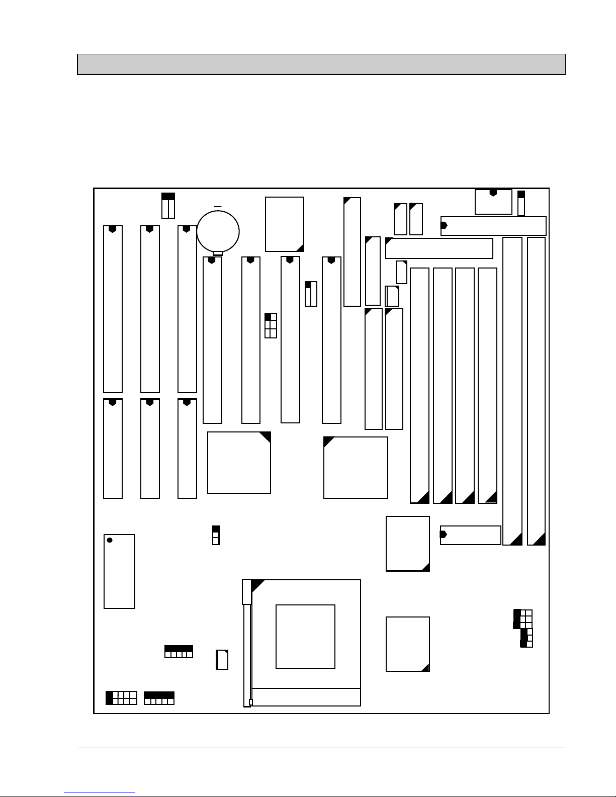
3. SYSTEM BOARD LAYOUT .............................................................................. 3-1
3.1 PT-5ITB VER. 1.x .......................................................................................... 3-1
4. HARDWARE SETUP .......................................................................................... 4-1
4.1 UNPACKING.................................................................................................. 4-1
4.2 HARDWARE CONFIGURATION.............................................................. 4-1
4.2.1 CONNECTORS .................................................................................... 4-2
4.2.2 JUMPERS.............................................................................................. 4-9
4.3 INSTALLING A CPU IN THE ZIF SOCKET ........................................... 4-17
4.4 INSTALLATION OF CPU COOLING FAN.............................................. 4-19
4.5 UPGRADING SYSTEM MEMORY............................................................ 4-20
4.5.1 Installing a SIMM module ................................................................... 4-20
4.5.2 Installing a DIMM Module .................................................................. 4-21
4.5.3 Memory Module Installing .................................................................. 4-22
5. AWARD BIOS SETUP ........................................................................................ 5-1
5.1 GETTING STARTED.................................................................................... 5-1
5.2 MAIN MENU.................................................................................................. 5-2
5.3 CONTROL KEYS .......................................................................................... 5-2
5.4 STANDARD CMOS SETUP ......................................................................... 5-3
5.5 BIOS FEATURES SETUP ............................................................................ 5-5
5.6 CHIPSET FEATURES SETUP .................................................................... 5-6
5.7 POWER MANAGEMENT SETUP.............................................................. 5-8
5.8 PNP/PCI CONFIGURATION ...................................................................... 5-9
5.9 INTEGRATED PERIPHERALS.................................................................. 5-11
5.10 LOAD SETUP DEFAULTS ........................................................................ 5-12
5.11 SUPERVISOR PASSWORD / USER PASSWORD ................................. 5-12
5.12 IDE HDD AUTO DETECTION ................................................................. 5-12
5.13 HDD LOW LEVEL FORMAT ................................................................... 5-12
5.14 SAVE &EXIT SETUP ................................................................................. 5-12
5.15 EXIT WITHOUT SAVING......................................................................... 5-13

PT-5ITB SYSTEM BOARD
ii
TRADEMARDKS
All trademarks used in this manual are the property of their respective owners.
NOTE
The “LOAD SETUP DEFAULTS” function loads the default settings directly from BIOS
default table, these default settings are the best-case values that will optimize system
performance and increase system stability. This function will be necessary when you
receive this system board, or the system CMOS data is corrupted.
By pressing “Enter” key. The SETUP default values will be loaded. (Please refers to the
Chapter 5 AWARD BIOS SETUP procedures in this manual.)
NOTICE
Information presented in this manual has been carefully checked for reliability; however,
no responsibility is assumed for inaccuracies. The information contained in this manual is
subject to change without notice.

PT-5ITB SYSTEM BOARD INTRODUCTION
1-1
1. INTRODUCTION
1.1 SYSTEM OVERVIEW
ThePT-5ITBPentium PCI Local Bus system mainboard is designed based on AT
form-factor on the Intel 82430TX PCIset system chipsets and Winbond I/O chipset, which
built-in two channels PIO and Bus Master Enhanced PCI IDE port, one Floppy Disk
control port, two high speed Serial ports (UARTs), one multimode Parallel port, one PS/2
keyboard port, one PS/2 mouse port, one IR port, two USB ports, and support PC97
specification. It is designed to fit a high performance, Pentium 75 MHz to 233 MHz based
solution for high-end and true GREEN-PC computer systems.
This system board supports the Peripheral Component Interconnect (PCI) Local Bus
standard (PCI Specification Rev. 2.1 compliant). It not only breaks through the I/O
bottlenecks if the traditional ISA mainboard, but also provides the performance needs for
networking and multi-user environments.

PT-5ITB SYSTEM BOARD SPECIFICATIONS
2-1
2. SPECIFICATIONS
¨Chipset
Intel 82430TX (82439TX (MTXC), 82371AB(PIIX4)) and Winbond W83977TF-A (-
AW / ATF-AW).
¨CPU (Jumper free)
Intel : Pentium processor and OverDrive processor (P54C / P54CS / P54CTB /
P55C) 90 / 100 / 120 / 133 / 150 / 166 / 200 / 233 MHz.
Cyrix : 6x86 / 6x86L - P150+ / P166+ / P200+.
6x86MX - PR166 / PR200 / PR233 / PR266.
AMD : K6 / PR2-166 / PR2-200 / PR2-233 / PR2-266.
IDT : C6 - DS180 / DS200
¨CPU Voltage (Jumpers Setting or Jumper free)
(1).CPU I/O voltage : +3.4V DC or +3.5V DC.
(2).CPU CORE voltage : “+2.0V~+3.5V DC” for Jumpers Setting.
+2.1V, +2.8V, +2.9V, +3.2V,+3.4V, +3.5V DC for Jumperless.
¨System Clock (Jumper free)
60 / 66.6 / 75 MHz.
¨Memory
DRAM : Two banks, each bank could be single or double sided, 8MB up to 256MB.
Supports fast page mode (FPM), Extended Data Out (EDO), and SDRAM
memory (Using 72-pin SIMM module x4, and 168-pin DIMM module x2).
DIMMs‘ operating voltage supports +3.3V DC.
SRAM : 256KB or 512KB pipelined burst SRAM on board.
¨BIOS
AWARD System BIOS. 128KB x 8 Flash ROM (for Plug & Play BIOS).
¨Expansion Slots
PCI Slots : 32-bit x 4 (All Master / Slave, PCI 2.1 Compliant).
ISA Slots : 16-bit x 3 (One PCI / ISA slot shared).
¨Supports AT and ATX Power connector.

PT-5ITB SYSTEM BOARD SPECIFICATIONS
2-2
¨ACPI (For ATX Power)
1.Power on by Panel-Switch, or Modem Ring-In.
2.Power on by Keyboard, PS/2 Mouse, or LAN Signal. (optional)
3.Power off (Soft-off) by OS or Panel-Switch.
¨WOL (optional)
One WOL connector supports Wake-On-LAN (For ATX Power).
¨IDE Ports
Two channel PIO and “Ultra DMA/33” Bus Master PCI IDE ports, which will connect
maximum 4 IDE devices like IDE Hard Disk and ATAPI CD-ROM device. PIO Mode
4 transfer rate up to 14 Mbytes/s transfer rates and supports “Ultra DMA/33” mode
transfers up to 33 Mbytes/sec.
¨USB Ports
Two Universal Serial Bus (USB) ports.
¨Super I/O Ports
1.Two high speed NS16C550 compatible Serial ports (UARTs).
2.One SPP / EPP / ECP mode Bi-directional parallel port.
3.One Floppy Disk Control port.
¨IR Port
One HPSIR and ASKIR or Faster IR (optional) compatible Infrared port. One
Consumer IR port (optional).
NOTE : Winbond W83977TF support HPSIR and ASKIR, W83977ATF support
Faster IR and Consumer IR.
¨Mouse and Keyboard
Supports PS/2 Mouse connector, PS/2 Keyboard connector (optional) and AT
Keyboard connector.
¨Support SB-LINK Connector
Support Creative PCI sound card, or others PCI sound card.
¨Hardware Monitoring (optional)
1.Include Positive Voltage, CPU temperature, and two fan speed monitoring.
2.Supports speaker alarm beep during these condition failure.
3.Protects CPU by slowing down the CPU during the CPU overheat.

PT-5ITB SYSTEM BOARD SPECIFICATIONS
2-3
¨Software compatibility
MS-DOS, Windows NT, OS/2, UNIX, NOVELL, Windows, Windows 95,
CAD/CAM, Memphis (Beta 2), ...etc, full tested.
¨DIMENSION
Width & Length : 220 mm x 231 mm.
Height : 3/4 inches with components mounted.
PCB Thickness : 4-layers, 0.05 inches normal.
Weight : 20 ounces.
¨ENVIRONMENT
Operating Temperature : 10°C to 40°C. (50°F to 104°F).
Require Airflow : 50 linear feet per minute across CPU.
Storage Temperature : -40°C to 70°C. (-40°F to 158°F).
Humidity : 0 to 90% noncondensing.
Altitude : 0 to 10,000 feet.

PT-5ITB SYSTEM BOARD SYSTEM BOARD LAYOUT
3-1
3. SYSTEM BOARD LAYOUT
3.1 PT-5ITB VER. 1.x
Explanation : All connectors, jumpers and components which are marked by a black
point on the corner means the pin-1 side of the connector, jumper and
component.
PCI 3
ISA2
CN4 AT POWER CON.
CN3
AT K/B
SIMM 2
SIMM 1
SIMM 4
SIMM 3
Intel
82439TX
BAT 1
CPU
CN11 LPT
COM B
CN5
CN1
PS/2
MS.
CN14
IR
CN18
U4 TAG
SPEAKER
KEYLOCK
HL
TL
SL
RS
Winbond
W83977TF
ISA1
ISA3
JP2
Socket 7
CN8
COM A
U5
CN17
USB 2 USB 1
JP1
U6
Intel
82371AB
JP4
JP11
JP3
PCI 1
ISA1
ISA2
ISA3
CN13 FDC.
CN10 IDE2
CN12 IDE1
DIMM 1
DIMM 2
Burst
Pipeline
SRAM
32K/64K *32
Pipeline
Burst
SRAM
32K/64K *32
JP5
SYS. BIOS
JP6
PCI 2
PCI 4
+CN6 ATX POWER CON.
PW
JP7
1
CN9
1
CN7
WOL
1 2
CN15
SB-LINK
1
CN16
CPU FAN
JP8
JP9
JP10
JP12
1
5
6
10
POWER FAN

PT-5ITB SYSTEM BOARD HARDWARE SETUP
4-1
4. HARDWARE SETUP
This chapter explains how to configure the mainboard hardware. When you are installing
the mainboard, you will have to make jumper settings and cable connections. Refer to this
chapter whenever you install or reconfigure your system.
4.1 UNPACKING
The system board package should contain the following parts :
The PT-5ITB system board.
OPERATION MANUAL.
Cable set for IDE and I/O device.
The mainboard contains electric sensitive components which can be easily damaged by
static electricity, so the mainboard should be left in its original packing until it is installed.
Unpacking and installation should be done on a grounded anti-static mat. The operator
should be wearing an anti static wristband, grounded at the same point as the anti-static
mat.
Inspect the mainboard carton for obvious damage. Shipping and handling may cause
damage to your board. Be sure there are no shipping and handling damages on the board
before proceeding.
After opening the motherboard carton, extract the mainboard and place it only on a
grounded anti-static surface with the component side up. Inspect the board again to see
whether there is any damage.
Press down on all of the socket IC‘s to make sure that they are properly seated. Do this
only with the board placed on a firm flat surface.
4.2 HARDWARE CONFIGURATION
Before the system board is ready for operating, the hardware must be configured to make
sure it will work properly with different environment. To configure the PT-5ITB system
board is a simple task, only a few jumpers, connectors, cables and sockets needs to be
selected and installed. (For the detailed locations of each component please refer to the
“system board layout figure” which appears in page 3-1.)

PT-5ITB SYSTEM BOARD HARDWARE SETUP
4-2
4.2.1 CONNECTORS
A connector is two or more pins that are used make connections to the system standard
accessories (such as power, mouse, printer,...etc.). The following is a list of connectors on
board, as well as descriptions of each individual connector.
(A) BAT1 Non-rechargeable battery (Using 3V Lithium battery : CR2032)
Pin # Assignment
+ Battery Positive
- Ground
(B) CN1 PS/2 Mouse converted connector
Pin # Assignment
1●1 Mouse Data
2 2 No Connection
3●3 Ground
4●4+5VDC
5●5 Mouse Clock
(C) CN2 PS/2 Keyboard connector (optional)
Pin # Assignment Pin # Assignment
1 Keyboard Data 2 No Connection
3 Ground 4 +5V DC
5 Keyboard Clock 6 No Connection
(D) CN3 AT Keyboard connector
Pin # Assignment Pin # Assignment
1 Keyboard Clock 2 Keyboard Data
3 No Connection 4 Ground
5+5VDC

PT-5ITB SYSTEM BOARD HARDWARE SETUP
4-3
(E) CN4 AT Power connector
Pin # Assignment
1●1 Power Good
2●2+5VDC
3●3 +12V DC
4●4 -12V DC
5●5 Ground
6●6 Ground
7●7 Ground
8●8 Ground
9●9-5VDC
10 ●10 +5V DC
11 ●11 +5V DC
12 ●12 +5V DC
(F) CN5 COM B (Serial Port 2) connector
COM 1/2/3/4, selected by BIOS setup, using IRQ 3 or 4
12 Pin#
Assignment Pin # Assignment
●● 1 DCD (Data Carrier Detect) 2 RD (Received Data)
●● 3 TD (Transmit Data) 4 DTR (Data Terminal Ready)
●● 5 Ground 6 DSR (Data Set Ready)
●● 7 RTS (Request To Send) 8 CTS (Clear To Send)
●● 9 RI (Ring Indicator) 10 No Connection
910
P8 P9

PT-5ITB SYSTEM BOARD HARDWARE SETUP
4-4
(G) CN6 ATX Power connector
Pin # Assignment Pin # Assignment
1 +3.3V DC 2 +3.3V DC
2 Ground 4 +5V DC
5 Ground 6 +5V DC
7 Ground 8 PW_OK
9 +5V DC 10 +12V DC
11 +3.3V DC 12 -12V DC
13 Ground 14 PS-ON
15 Ground 16 Ground
17 Ground 18 -5V DC
19 +5V DC 20 +5V DC
(H) CN7 WOL (Wake On LAN) connector
Pin # Assignment
●1 1 5V standby
●2 2 Ground
●3 3 WOL Signal
(I) CN8 COM A (Serial Port 1) connector
COM 1/2/3/4, selected by BIOS setup, using IRQ4 or 3
12 Pin#
Assignment Pin # Assignment
●● 1 DCD (Data Carrier Detect) 2 RD (Received Data)
●● 3 TD (Transmit Data) 4 DTR (Data Terminal Ready)
●● 5 Ground 6 DSR (Data Set Ready)
●● 7 RTS (Request To Send) 8 CTS (Clear To Send)
●● 9 RI (Ring Indicator) 10 No Connection
910
(J) CN9 POWER FAN connector
Pin # Assignment
●1 1 GND
●2 2 +12V DC
●3 3 SIN (Fan Sense Signal)

PT-5ITB SYSTEM BOARD HARDWARE SETUP
4-5
(K) CN10 IDE 2 connector (Secondary IDE Port, using IRQ15)
(L) CN11 Parallel Port Connector
(Supports SPP/EPP/ECP mode, using IRQ7 or IRQ5, ECP using DMA
channel 3 or 1, selected by CMOS setup)
114 Pin#Assignment Pin # Assignment
●● 1 STROBE- 14 AUTO FEED-
●● 2 Data Bit 0 15 ERROR-
●● 3 Data Bit 1 16 INIT-
●● 4 Data Bit 2 17 SLCT IN-
●● 5 Data Bit 3 18 Ground
●● 6 Data Bit 4 19 Ground
●● 7 Data Bit 5 20 Ground
●● 8 Data Bit 6 21 Ground
●● 9 Data Bit 7 22 Ground
●● 10 ACK- 23 Ground
●● 11 BUSY 24 Ground
●● 12 PE 25 Ground
●● 13 SLCT 26 No Connection
13 26
(M)CN12 IDE 1 connector (Primary IDE Port, using IRQ 14)
(N)CN13 Floppy Disk Control Port connector (Using IRQ6, DMA channel 2)
(O)CN14 IR / FIR (Infrared Rays) connector
Pin # Assignment
●1 1 +5V DC
2 2 No Connection (Fast IR Receive, optional for W83977ATF)
●3 3 IR Receive
●4 4 Ground
●55IRTransmit

PT-5ITB SYSTEM BOARD HARDWARE SETUP
4-6
(P) CN14 Consumer IR connector
(optional and available only while U10 using W83977ATF I/O Chip)
Pin # Assignment
●6 6 +5V DC
●77IRTransmit
●8 8 Consumer IR Receive
●9 9 Ground
(Q) CN15 SB-LINK connector
(For PCI bus sound cards. Such as CreativeLabs EMU8008 sound chip)
12 Pin#
Assignment Pin # Assignment
●● 1 GNT# 2 Ground
●3Key 4REQ#
●● 5 Ground 6 SERIRQ
56
(R) CN16 CPU Cooling Fan Power connector
Pin # Assignment
●1 1 Ground
●2 2 +12V DC
●3 3 Fan Sense Signal
(S) CN17 USB Port 1 (Universal Serial Bus port 1) connector
1Pin#
Assignment
●1+5VDC(REDWIRE)
●2 DATA- (WHITE WIRE)
●3 DATA+ (GREEN WIRE)
●4 Ground (BLACK WIRE)
●5 Ground (BLACK WIRE)
5

PT-5ITB SYSTEM BOARD HARDWARE SETUP
4-7
(T) CN18 USB Port 2 (Universal Serial Bus port 2) connector
1Pin#
Assignment
●1+5VDC(REDWIRE)
●2 DATA- (WHITE WIRE)
●3 DATA+ (GREEN WIRE)
●4 Ground (BLACK WIRE)
●5 Ground (BLACK WIRE)
5
(U) KEYLOCK Front Panel Power LED & Key-Lock connector
1Pin#
Assignment
●1 Pullup (+5V DC for Power LED)
●2 No Connection
●3 Ground
●4 Keyboard Lock
●5 Ground
5
(V) SPEAKER Speaker connector
1Pin#
Assignment
●1+5VDC
●2 No Connection
●3 No Connection
●4 Speaker Data Signal
4
(W) RS Reset Button connector
Open : No action Short : System Reset
Pin # Assignment Pin # Assignment
1 Ground 2 Reset Control
(X) HL IDE HDD LED connector
Pin # Assignment Pin # Assignment
1 Pullup (+5V DC) 2 Signal Pin

PT-5ITB SYSTEM BOARD HARDWARE SETUP
4-8
(Y) TL Turbo LED connector
Pin # Assignment Pin # Assignment
1 Pullup (+5V DC) 2 Ground
(Z) SL Sleep LED connector
ATX Power Off : LED Turn On
ATX Power On : LED Turn Off
Pin # Assignment Pin # Assignment
1 Signal Pin 2 Ground
(AA) PW
(a.) For ATX power
Front Panel Power Switch connector & External SMI button connector
(selected by BIOS setup : Soft-off by PWR-BTTN)
1. Instant-Off 2.Delay 4 Sec.
Once pressed : Power On Once pressed : Power On
Next pressed : Power Off Next pressed : Suspend mode
Pressed and after 4 second : Power Off
(b.) For AT power
External SMI button connector (BIOS setup : Soft-off by PWR-BTTN must
be setted Delay 4 Sec.)
Once pressed : Suspend mode.
Next pressed : Full on mode.

PT-5ITB SYSTEM BOARD HARDWARE SETUP
4-9
4.2.2 JUMPERS
A jumper is two, three or more pins which may or may not be covered by a plastic
connector plug (mini-jumper). A jumper is used to select different system options. Please
make sure all jumpers at correct position before this system board used.
(A) JP1, JP2, JP3, JP4, JP5, JP6 CPU type selection (For Jumpers Setting)
NOTE :
When JP1, JP2, JP3, JP4, JP5, JP6 are empty, then this mainboard is jumperfree for CPU
type selection, so you must enter the system BIOS to setup the correct CPU type. Please
you refer to this manual the page 5-6, the 5.6 CHIPSET FEATURES SETUP item.
(1) 60MHz x 1.5 (2) 66MHz x 1.5 / 66MHz x 3.5
JUMPERS CPU TYPE JUMPERS CPU TYPE
1 2 3 Intel 80502-90 1 2 3 Intel 80502-100
1¡ ¡ ●JP1 PODP3V150 1 ¡ ¡ ●JP1 80503-233
1¡ ¡ ●JP2 PODPMT60X150 1 ¡ ¡ ●JP2 PODP3V166
1●¡ ¡ JP3 1 ¡ ¡ ●JP3 PODPMT66X166
1●● JP4 1 ●● JP4 AMD K6/PR2-233
1●● JP5 1 ●● JP5
1●● JP6 1 ●● JP6 Cyrix 6x86 MX
-PR266
(3) 60MHz x 2 (4) 66MHz x 2
JUMPERS CPU TYPE JUMPERS CPU TYPE
1 2 3 Intel 80502-120 1 2 3 Intel 80502-133
1¡ ¡ ●JP1 1 ¡ ¡ ●JP1
1¡ ¡ ●JP2 1 ¡ ¡ ●JP2
1●¡ ¡ JP3 1 ¡ ¡ ●JP3
1¡ ¡ JP4 1 ¡ ¡ JP4
1●● JP5 1 ●● JP5 Cyrix 6x86 / 6x86L
1●● JP6 Cyrix 6x86 / 6x86L 1 ●● JP6 -P166+
-P150+ 6x86MX-PR166

PT-5ITB SYSTEM BOARD HARDWARE SETUP
4-10
(5) 75MHz x 2 (6) 60MHz x 2.5
JUMPERS CPU TYPE JUMPERS CPU TYPE
1 2 3 1 2 3 Intel 80502-150
1¡ ¡ ●JP1 1 ¡ ¡ ●JP1
1●¡ ¡ JP2 1 ¡ ¡ ●JP2
1¡ ¡ ●JP3 1 ●¡ ¡ JP3
1¡ ¡ JP4 1 ¡ ¡ JP4
1●● JP5 Cyrix 6x86 / 6x86L 1 ¡ ¡ JP5
1●● JP6 -P200+ 1 ●● JP6 Cyrix 6x86MX
6x86MX-PR200 -PR166
(7) 66MHz x 2.5 (8) 75MHz x 2.5
JUMPERS CPU TYPE JUMPERS CPU TYPE
1 2 3 Intel 80502-166 1 2 3
1¡ ¡ ●JP1 80503-166 1 ¡ ¡ ●JP1
1¡ ¡ ●JP2 1 ●¡ ¡ JP2
1¡ ¡ ●JP3 AMD K6/PR2-166 1 ¡ ¡ ●JP3
1¡ ¡ JP4 1 ¡ ¡ JP4
1¡ ¡ JP5 1 ¡ ¡ JP5
1●● JP6 Cyrix 6x86MX 1 ●● JP6 Cyrix 6x86MX
-PR200 -PR233
(9) 60MHz x 3 (10) 66MHz x 3
JUMPERS CPU TYPE JUMPERS CPU TYPE
1 2 3 1 2 3 Intel 80502-200
1¡ ¡ ●JP1 1 ¡ ¡ ●JP1 80503-200
1¡ ¡ ●JP2 IDT C6-DS180 1 ¡ ¡ ●JP2 IDT C6-DS200
1●¡ ¡ JP3 1 ¡ ¡ ●JP3
1●● JP4 1 ●● JP4 AMD K6/PR2-200
1¡ ¡ JP5 1 ¡ ¡ JP5
1●● JP6 1 ●● JP6 Cyrix 6x86MX
-PR233

PT-5ITB SYSTEM BOARD HARDWARE SETUP
4-11
(11) 75MHz x 3 (12) 60MHz x4
JUMPERS CPU TYPE JUMPERS CPU TYPE
123 123
1¡ ¡ ●JP1 1 ¡ ¡ ●JP1
1●¡ ¡ JP2 1 ¡ ¡ ●JP2
1¡ ¡ ●JP3 1 ●¡ ¡ JP3
1●● JP4 1 ¡ ¡ JP4
1¡ ¡ JP5 1 ●● JP5
1●● JP6 Cyrix 6x86MX 1 ¡ ¡ JP6
-PR266
(13) 66MHz x 4 (14) 75MHz x 4
JUMPERS CPU TYPE JUMPERS CPU TYPE
123 123
1¡ ¡ ●JP1 1 ¡ ¡ ●JP1
1¡ ¡ ●JP2 1 ●¡ ¡ JP2
1¡ ¡ ●JP3 AMD K6/PR2-266 1 ¡ ¡ ●JP3
1¡ ¡ JP4 1 ¡ ¡ JP4
1●● JP5 1 ●● JP5
1¡ ¡ JP6 1 ¡ ¡ JP6
(15) 66MHz x 4.5 (16) 66MHz x 5
JUMPERS CPU TYPE JUMPERS CPU TYPE
123 123
1¡ ¡ ●JP1 1 ¡ ¡ ●JP1
1¡ ¡ ●JP2 1 ¡ ¡ ●JP2
1¡ ¡ ●JP3 AMD K6/PR2-300 1 ¡ ¡ ●JP3
1¡ ¡ JP4 1 ●● JP4
1¡ ¡ JP5 1 ¡ ¡ JP5
1¡ ¡ JP6 1 ¡ ¡ JP6

PT-5ITB SYSTEM BOARD HARDWARE SETUP
4-12
(B) JP8, JP9, JP10, JP11, JP12 CPU CORE voltage selection (for Jumpers Setting or
Jumper free)
NOTE :
The CPU CORE voltage for Jumper free support 2.1V, 2.8V, 2.9V, 3.2V, 3.4V, 3.5V DC
only, so if your CPU CORE voltage os not these voltage, please use those JP11, JP12,
JP13, JP14, JP15 to set the correct CPU CORE voltage.
JUMPERS CORE Voltage IO Voltage CPU TYPE REMARKS
1 2 AUTO AUTO For Jumper
1●●
JP11 free supports
1●●
JP12 2.1V, 2.8V
1●●
JP13 2.9V, 3.2V
1●●
JP14 3.4V, 3.5V
1●●
JP15
JUMPERS CORE Voltage IO Voltage CPU TYPE REMARKS
1 2 3.5V 3.5V Cyrix 6x86 For
1¡ ¡ JP11 3.5V 3.5V IDT C6 Jumper free
1¡ ¡ JP12
1¡ ¡ JP13
1¡ ¡ JP14
1¡ ¡ JP15
JUMPERS CORE Voltage IO Voltage CPU TYPE REMARKS
1 2 3.4V 3.4V Intel P54C (80502) For
1¡ ¡ JP11 3.4V 3.4V Cyrix 6x86 Jumper free
1¡ ¡ JP12
1¡ ¡ JP13
1¡ ¡ JP14
1●●
JP15
Table of contents
Other AZZA Motherboard manuals