AZZA P4XE-ANB User manual

The P4XE-ANB Mainboard Page 1
P4XE
P4XEP4XE
P4XE-
--
-ANB
ANBANB
ANB
Mainboard Manual
Mainboard ManualMainboard Manual
Mainboard Manual
Socket 478 DDR ATX Mainboard
Version 1.x
UM-P4XE-ANB-E1
Rev 1.0V
Creation Date: 17 January 2003

The P4XE-ANB Mainboard
Page 2
Copyright
This publication contains information that is protected by copyright.
No part of it may be reproduced in any form or by any means or used
to make any transformation adaptation without prior written permis-
sion from the copyright holders. This publication is provided for infor-
mational purposes only. The manufacturer makes no representations
or warranties with respect to the contents or use of this manual and
specifically disclaims any express or implied warranties of merchant-
ability or fitness for any particular purpose. The user will assume the
entire risk of the use or the results of the use of this document. The
manufacturer reserves the right to revise this publication and make
changes to its contents at any time, without prior notice.
2002. All Rights Reserved.
Trademarks
Microsoft®, MS-DOS®, WindowsTM, Windows®95 and Windows®98 are
registered trademarks of Microsoft Corporation. Intel®PentiumTM4 is a
registered trademark of Intel Corporation. Phoenix Award is the regis-
tered trademark of Phoenix Award Software, Inc. Other trademarks
and registered trademarks of products appearing in this publication
are the properties of their respective holders.
Package Checklist
This package contains the following items:
!Mainboard
!User’s manual
!One IDE cable
!One 34-pin floppy disk drive cable
!One Driver Utility CD
If any of these items are damaged or missing, please contact your
dealer or sales representative for assistance.
Technical Support
If you require additional information or assistance during installation
please contact your dealer. Your dealer will be able to provide the lat-
est information.
User’s Notice

The P4XE-ANB Mainboard Page 3
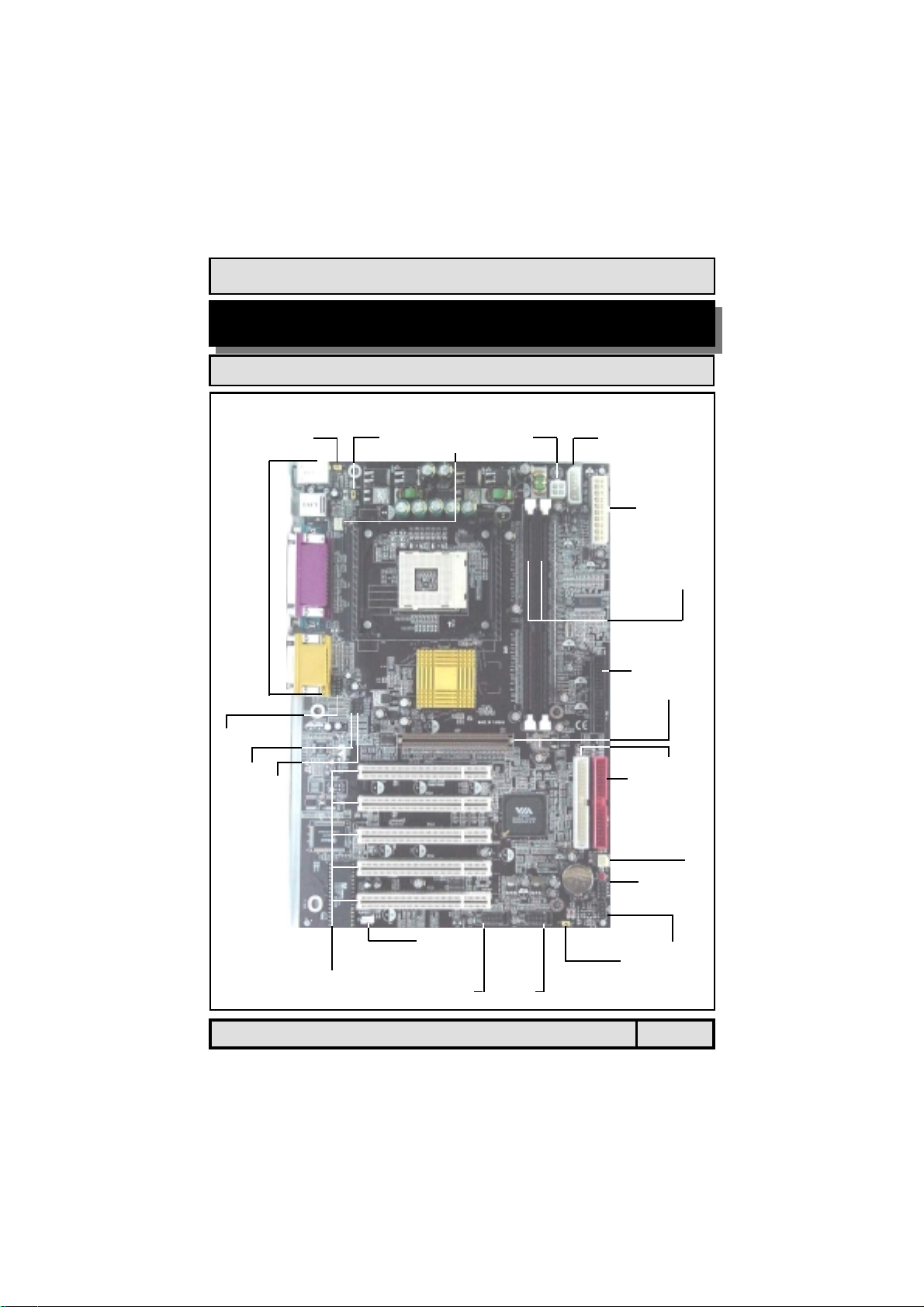
!"
#$%&'(%
&%)*+$%
,&%)-.
-%+/%
-%&'%
#'%&%01)'%-%
20)'%&%
!"
#$
! %
&'!(&))'*)!+%
,-%
,**#- )
!#%)# )
!", , )
&.!/%$**# )
012&".01 ) 3
45(4-050&1+ )3
3"%67"%67"%67"%6 )8
8,&$ )8
3&%)"%4%
!49!/525:%$*%/) )
%9%# )
;9; )
<%9<6$ )
5&'/4%
3%*- )(%!=+
3,!!/(!4<+
Table Of Contents

The P4XE-ANB Mainboard
Page 4
6%
8!%2=# )
8!%2$ )
8%! )
8!! )
8"%6$("%6+!
8&$2' )
1)'&.%
>!9=#!/
>!9"%67"%6!/
>!9 5%
#+"-&&&'2
#
##&&&'
#"-&$%
#,+'%$%
#3-.'+%
#5.)&'
#6!7-(.8
#*+&%
#8$97:.
#$ &(4(%7');4(%
,0%$
5*?$
#&&'%%%2%%%
%%$*!/
%"!/
##&<&'7=+&.
%@:%$*
:4$%A
Table Of Contents

The P4XE-ANB Mainboard Page 5
Introduction
PC 99 ATX External Connector
JP1:KB
POWER
JP2:USB
POWER
CN15-B:
ATX12V
CN15-D:
AUX12V
CN15-A: ATX
DIMM1
DIMM2
CN8: FDC
AGP Slot
CN9: IDE1
CN10: IDE2
CN17: CHASSIS FAN
RS
HL
SL
PW
SPK
PWRLED
JP4:
Clear CMOS
CN32:USB5
CN38:USB6
CN30:USB3
CN31:USB4
CN16: WOL
PCI1
PCI2
PCI3
PCI4
PCI5
CN45: AUX-IN
CN21: CD-IN
CN39: Front Audio
CN13:
CPU FAN

The P4XE-ANB Mainboard
Page 6
1.2.1. The P4XE-ANB Mainboard
The P4XE-ANB mainboard is a Pentium™ 4 DDR platform. Onboard it pro-
vides two DDR DIMM slots (support DDR200/DDR266), six USB2.0 ports, five
PCI slots and one 2X/4X AGP slot. There are also two fan connectors (for addi-
tional thermal protection) and three power supply connectors. Additionally, it
comes with Onboard Audio (AC’97 2-channel) and WOL (Wake-On-LAN) con-
nector that enables it to be “woken up” from a soft-off power state when it
receives a signal from the LAN. Other onboard connectors include CD-IN, AUX-
IN and Front Audio connectors etc.
1.2.2. Mainboard Dimension
Width 305 mm
Length 200 mm
1.2.3. Environmental Limitations
Operating Temperature: 10°C to 40°C (50°F to 104°F)
Required Airflow: 50 linear feet per minute across the CPU
Storage Temperature: -40°C to 70°C (-40°F to 158°F)
Humidity: 0 to 90% non-condensing
Altitude: 0 to 10 000 feet
Introduction
Processor
The P4XE-ANB mainboard supports Intel®Pentium™ 4 Socket 478 CPUs.
Chipsets
Northbridge: VIA P4X266E
Southbridge: VIA VT8235 (CD)
I/O Chipset: Winbond W83697HF
!"#$!
PC 99 ATX External Connector
CN2: PS/2 Mouse
CN1: PS/2 Keyboard
CN5: LPT CN18: Audio/Game
CN7: USB2
CN6: USB1 CN4: COM2
CN3: COM1 SPK OUT
LINE IN
MIC

The P4XE-ANB Mainboard Page 7
CPU Switching Voltage Regulator
The mainboard is equipped with a switching voltage regulator that automati-
cally detects a DC power supply from +1.10V to +1.85V.
System Memory
The mainboard uses Double Data Rate Dual Inline Memory Modules (DDR
DIMM). Each mainboard has two 184-pin DIMM sockets which support 2.5V
(power level) single-sided or double-sided PC1600 (DDR200), PC2100
(DDR266) DDR DIMM modules. The maximum memory supported by the
mainboard is 1 GB.
Expansion Slots
The mainboard is equipped with five dedicated PCI slots and one 1.5V 2X/4X
AGP slot.
Onboard Audio Features
The mainboard supports Microsoft DirectSound/DirectSound 3D and AC97 Full
Duplex.
WOL (Wake-On-LAN) Port
The mainboard supports Wake-On-LAN functionality.
Word Size
Data Path: 8-bit, 16-bit, 32-bit, 64-bit
Address Path: 32-bit
Front Side Bus Frequency (FSB)
The Front Side Bus Frequency (FSB) is 400/533 MHz.
BIOS
!Phoenix Award BIOS, Windows 95/98 Plug and Play (PnP) compatible
!Supports SCSI sequential boot-up
!2 Mb flash ROM for easy BIOS upgrades
!Supports DMI2.0 function
Desktop Management Interface (DMI)
The mainboard comes with DMI 2.0 built into the BIOS. The DMI utility in the
BIOS will automatically record different information about your system
configuration and store this information in the DMI pool, which is a part of the
system board's Plug and Play BIOS. DMI, along with the appropriately
networked software, is designed for easy inventory, maintenance and the
simplified troubleshooting of computer systems.
Introduction

The P4XE-ANB Mainboard
Page 8
Introduction
Connectors
!Two IDE connectors (support ATA 33/66/100/133)
!One Floppy Drive connector supports up to two 2.88 MB floppy drives
!One 20-pin ATX power supply connector
!One 2x2 ATX 12V power supply connector
!One 1x4 AUX12V power supply connector
!Two fan connectors
!One CD-IN connector
!One AUX-IN connector
!One WOL (Wake-On-LAN) connector
!One Front Audio connector
ATX Double Deck Ports (PC 99 color-coded connectors)
!Two USB2.0 ports
!Two external DB-9 serial port connectors: COM 1, COM 2 (UART)
!One SPP/ECP/EPP DB-25 parallel port
!One mini-DIN-6 PS/2 mouse port
!One mini-DIN-6 PS/2 keyboard port
!One GAME port
!Three audio jacks: SPK-OUT, LINE-IN and MIC-IN
PCI Bus Master IDE Controller
!Two PCI IDE interfaces support up to four IDE devices.
!This mainboard supports ATA 33/66/100/133 hard drives.
!PIO Mode 3 and Mode 4 Enhanced IDE (data transfer rate up to
16.6MB/sec.).
!Bus mastering reduces CPU utilization during disk transfer.
!Supports ATAPI CD-ROM, LS-120 and ZIP.
USB 2.0 Ports
USB allows data exchange between your computer and a wide range of
simultaneously accessible external Plug and Play peripherals. The mainboard is
equipped with six USB 2.0 connectors. USB1 and USB2 are external connec-
tors. They can be found on the PC99 ATX connector. The other USB connectors
are internal connectors and can be used to connect other USB devices. (Cables
for the internal connectors are sold separately).
Note: The PIN assignment of the internal USB 2.0 connectors (CN30, CN31,
CN32 and CN38) are follow the specifications of Intel standard.

The P4XE-ANB Mainboard Page 9
Introduction
The mainboard is capable of monitoring the following health conditions of your
system:
1. Processor temperature. It has an overheat alarm.
2. VCORE/3.3V/5V/12V/-12V voltages and failure alarm.
3. Processor and chassis fan speeds. It has a failure alarm for these fans.
4. Read back capability that displays temperature, voltage and fan speed.
Hardware Monitoring System Utility
The mainboard comes with the Hardware Monitoring System utility contained
on the CD. It is capable of monitoring the system’s hardware conditions such
as the temperature of the processor, voltage, and the speed of both the CPU
and chassis fans. You are allowed to manually set a range to the items being
monitored. If the values are over or under the set range a warning message
will automatically pop up. We recommend that you use the Default Settings,
which are the ideal settings that will maintain the system in a good working
condition. To install this utility, please insert the CD into the CD-ROM drive.
The auto run screen (Driver Utility) will automatically appear. Click the Hard-
ware Monitoring button, choose the chipset, model number and the OS that is
installed. Please refer to the CD “Readme” file for further installation instruc-
tions.
Note: Only use this utility in Windows operating systems.
Dual Function Power Button
Depending on the setting in the Soft-Off By Power-Button field of the Power
Management Setup, this switch allows the system to enter the Soft-Off or
Suspend mode.
RTC Timer to Power-on the System
The RTC installed on the system board allows your system to automatically
power-on at a set date and time.
Wake-On-LAN Ready
The Wake-On-LAN function allows the network to remotely wake up a Soft
Power Down (Soft-Off) PC. Your LAN card must support the remote wakeup
function. The 5V SB power source of your power supply must be at least
720mA.
ACPI Ready
The mainboard is designed to meet the ACPI (Advanced Configuration and
Power Interface) specification. ACPI has energy saving features that support
OS Direct Power Management (OSPM) for round the clock PC operation.
%"!&'(
)"!&*+ !

The P4XE-ANB Mainboard
Page 10
The following is a checklist of all the expansion slots, jumpers and connectors
that should be configured on your mainboard before you can run your PC.
'!+,!
Installation Checklist
Expansion Slots and Sockets
CPU Socket
DIMM Slots
PCI Slots
AGP Slot
Intel®Pentium™ 4 Socket 478 CPU
Two 184-pin Slots
Five 32-bit PCI Slots
One 2X/4X Accelerated Graphics Port Slot
Internal Connectors
CN8
CN9
CN10
CN13
CN15-A
CN15-B
CN15-D
CN16
CN17
CN21
CN30/31
CN32/38
CN39
CN45
Floppy Drive Connector
Primary IDE
Secondary IDE
CPU Fan
ATX Power Supply
ATX 12V Power Supply
Auxiliary ATX 12V Power Supply
Wake-On-LAN Connector
Chassis Fan
CD Audio In
Universal Serial Bus 3/4
Universal Serial Bus 5/6
Front Audio Connector
Auxiliary In Connector
FDC
IDE1
IDE2
CPU FAN
ATX
ATX12V
AUX12V
WOL
CHASSIS FAN
CD-IN
USB3/4
USB5/6
FRONT AUDIO
AUX-IN
CN1
CN2
CN3
CN4
CN5
CN6
CN7
CN18
PS/2 Keyboard Connector
PS/2 Mouse Connector
Serial Port 1
Serial Port 2
Parallel Port
Universal Serial Port 1
Universal Serial Port 2
Audio/GAME Port
K/B
M/S
COM1
COM2
LPT
USB1
USB2
AUDIO/GAME
External Connectors
Hardware Installation

The P4XE-ANB Mainboard Page 11
You need to complete the following installation steps before you can use your
PC. !Check and set the mainboard settings;
!Install the Central Processing Unit (CPU);
!Install the memory modules;
!Install the expansion cards;
!Connect the ribbon cables, panel wires and power supply;
!Setup the system BIOS.
'!"#!
Hardware Installation
Installation Checklist (Continued)
Speaker and Power LED Connectors
PW
HL
SL
RS
Power On/Off and Suspend Switch Connector
HDD LED Connector
Standby LED Connector
Reset Button Connector
Speaker and Power LED Connectors
PWRLED
SPK Power LED
Speaker Connector
Jumpers and Switches
JP1
JP2
JP4
K/B Power
USB1,2 Power
Clear CMOS
Note: Before you start installing your mainboard we strongly recommend that
you use a grounded anti-static mat. We further recommend that you attach an
anti-static wristband, which is grounded at the same location as the mat, to
your wrist.

The P4XE-ANB Mainboard
Page 12
Hardware Installation
#!"!-.&#!'!
!
"
"!
"#
"$
"%
"&
"
!
"
"!
"#
"$
"#
"$
"%
"&
"%
"&
"

The P4XE-ANB Mainboard Page 13
2.4.2. Memory Modules
The mainboard has two 184-pin DDR DIMM slots which are located on the
right-hand side of the board. The maximum supported memory is 1 GB. To
install the DIMMs into these slots, make sure the white lever at each side of
the slot has been pulled down to an angle of approximately 45. Make sure
that the DIMM is in the correct orientation. Place the DIMM on the slot and
push down firmly.The white levers will come back up and lock the module in
place.
Note: The system memory supports 128 MB, 256 MB and 512 MB technologies
for x8 and x16 devices.
Hardware Installation
2.4.1. Installation of the CPU
To install your processor, please complete the following set of instructions:
1. Locate a small dot marked on the top of the CPU. This mark indicates Pin 1
of the CPU.
2. Locate Pin 1 for the socket on the mainboard.
3. There is a lever on the side of the socket. First push this lever sideways
and then lift it to a 90-degree angle.
4. Insert the CPU into the socket. Please make sure that Pin 1 of the CPU is
inserted into Pin 1 of the socket.
5. When the CPU is installed correctly push the lever back into place.
6. Install a proper heat sink with cooling fan for proper heat dissipation.
)/-&#!"!
* *
Top View of a 184-pin DIMM Slot
IMPORTANT: CPU COOLING FAN
Please ensure that you have an approved heat sink with cooling fan. Without a
proper heat sink with cooling fan you will damage both the mainboard and
CPU.
Important: The DIMM’s can only be fitted into the slots in one orientation.
Make sure that the DIMM’s are in the correct orientation and the pins are cor-
rectly aligned before you insert them.

The P4XE-ANB Mainboard
Page 14
2.4.3. PCI Slots
The mainboard comes with five PCI slots. They are located on the left-hand
side of the board. Both PCI and PCI expansion cards may require IRQ’s. This
mainboard complies with Plug and Play (PnP) specifications. Whenever a PnP
compliant card is added the system will automatically be configured and the
IRQ’s will be assigned automatically.
Hardware Installation
#$6<&$A)4/0
$ 7 4/ 8 %) 7 4/ 8 4/ #$ # :0
*)#*/#**A$$
%05%/#$$A4/)*$#**A
/4/A
*$*9
+ <$)$#B))$6#A:0
, )A%#
+ "%# A$"#$)$#4/$
6
+ <$)##$)*$6
*)))$&)'*)!(&'!+*$
* *
Top View of a 32-bit PCI Slot
2.4.4. AGP (Accelerated Graphics Port) Slot
AGP is a dedicated bus slot. It operates at 66 MHz and transfers data at a rate
of 1066 MB/s (4x). This allows 3D applications to run more smoothly. The
mainboard comes with an AGP slot which is able to support 2x/4X AGP cards.
Top View of an AGP Slot
*

The P4XE-ANB Mainboard Page 15
Hardware Installation
2.5.1. Floppy Disk Drive Connector
Connector: CN8 (FDC)
Type: 34 pin block
The FDC connector can support two floppy drives. It is located at the front of
the mainboard. To connect, use the ribbon cable that has been provided. Make
sure that the red strip is connected to Pin 1 of the connector.
%'!
2.5.2. Primary and Secondary IDE Connectors
Connector: CN9 (IDE1)/CN10 (IDE2)
Type: 40 pin block
The mainboard has two IDE connectors: a primary and secondary. Each IDE
connector can support two IDE drives. The mainboard each can therefore sup-
port up to four IDE devices. If you install two hard drives, you need to config-
ure the second drive to Slave mode. Please refer to your hard drive manual
for the appropriate jumper settings.
2.5.3. CPU Fan and Chassis Fan Connectors
Connector: CN13 (CPU FAN)/CN17 (CHASSIS FAN)
Type: 3 pin
The cooling fans must be connected to their respective power connectors. If
you have installed the hardware-monitoring feature you will be able to monitor
the rotating speed of the CPU cooling fan in your Windows operating system.
!1
3!
Top View of a Floppy
Disk Drive Connector
Top View of an
IDE Connector
!
PIN 1
Ground
+12V DC
Fan Signal
Top View of a Fan Connector Front View of a Fan Connector
1 2 3
Ground
+12V DC
Fan Signal

The P4XE-ANB Mainboard
Page 16
Hardware Installation
2.5.4. ATX Power Supply Connectors
Connector: CN15-A/CN15-B/CN15-D
Type: 20 pin block/2x2 12V/1x4 AUX12V
The mainboard comes with three onboard power supply connectors labeled
CN15-A, CN15-B and CN-15D. CN15-A and CN15-B are regular ATX12V power
supply connectors. CN15A and CN15D are regular ATX power supply connec-
tors. The auxiliary power supply connector (CN15-D) is for a +12V and +5V
power supply. These increased power supplies are necessary to provide extra
power for the slot. The ATX 12V power supplies are all downward compatible
with standard ATX power supplies.
ATX Power Supply Connector
Pin 1
+3.3VDC
+3.3VDC
COM
+5VDC
COM
+5VDC
COM
PWR_OK
+5VSB
+12VDC
+3.3VDC
-12VDC
COM
PS_ON#
COM
COM
COM
-5VDC
+5VDC
+5VDC
Pin 11
Pin 1 Pin 3
COM
COM
+12VDC
+12VDC
ATX12V Power Supply Connector Auxiliary Power Supply Connector
Pin 4
Pin 3
Pin 2
Pin 1
+5VDC
COM
COM
+12VDC

The P4XE-ANB Mainboard Page 17
Hardware Installation
2.5.6. WOL (Wake-On-LAN) Connector
Connector: CN16 (WOL)
Type: 3 pin
The mainboard has a WOL (Wake-On-LAN) connector. This connector must be
connected to a LAN card that has Wake-On-LAN (WOL) output. This connector
powers up the system when a wakeup packet or signal is received through the
LAN card.
In order to use the WOL LAN card to trigger the power on the PC system, the
switching power supply must have the ability to provide a driving current of at
least 720 mA and be connected to a “5V standby” voltage.
WOL5V_SB
Ground
1 5V_SB
2 Ground
3 WOL
Top View of a WOL Connector Front View of a WOL Connector
2.5.5. CD-IN/AUX-IN Connector
Connector: CN21 (CD-IN)/CN45 (AUX-IN)
Type: 4 pin un-housed
The mainboard has one CD-IN connector and one AUX-IN connector. The CD-
IN connector is used to connect the CD ROM audio out and allows the system
to receive audio input from the CD ROM. The AUX-IN connector allows the
system to receive signals from other audio devices like a radio or tape.
1 Left Channel CD/AUX-IN
2 Ground
3 Ground
4 Right Channel CD/AUX-IN
Top View of a CD/AUX-IN
Connector Front View of a CD/AUX-IN
Connector
RightChannel
CD-IN/
AUX-IN
Left Channel
CD-IN/
AUX-IN
Ground Ground

The P4XE-ANB Mainboard
Page 18
Hardware Installation
2.5.8. Front Audio Connector
> 1(,&$+
'> *
This connector is designed to be used with a Front-Utility Panel. The utility
panel was developed so that a user is able to bring the speaker out, micro-
phone in connectors to the front of their PC. This makes things like plugging in
speakers and earphones much less troublesome.
10
9
8
7
6
5
4
3
2
1
Pin Pin
1 MIC-IN (Left) 2 Ground
3 MIC-IN (Right) 4 NC
5 LINE-OUT (Right) 6 NC
7 NC 8 Key
9 LINE-OUT (Left) 10 NC
Front Audio Connector
2.5.7. USB3, USB4, USB5, USB6 Connectors
Connector: CN30 (USB3)/CN31 (USB4)/CN32 (USB5)/CN38 (USB6)
Type: 5 pin
You already have two USB2.0 ports available, USB1 and 2 (see external con-
nectors). The internal USB connectors allow you to add on an optional kit to
expand the total number of USB ports available. The mainboard has four inter-
nal USB2.0 connectors (CN30/CN31/CN32/CN38). This enables you to use an
extra four USB devices. Cable for these additional connectors needs to be pur-
chased separately.
Note: The PIN assignment of the internal USB 2.0 connectors (CN30, CN31,
CN32 and CN38) are follow the specifications of Intel standard.
Top View of USB Ports Front View of USB Ports
9 Key
7 Ground
5 Data+
3 Data-
1 VCC 2 VCC
4 Data-
6 Data+
8 Ground
10NC
USB3/5 USB4/6
2 VCC
4 Data -
6 Data +
8 Ground
10 NC
USB4/6
1 VCC
3 Data -
5 Data +
7 Ground
USB3/5
9 Key

The P4XE-ANB Mainboard Page 19
2.6.1 PW: Power On/Off and External Suspend Switch Connector
The Power On/Off connector has two functions. It can be the Power Switch or
Suspend Switch of your PC system. You can either choose “Delay 4 Sec” or
“Instant OFF” .
Option 1: If you choose “Delay 4 Sec.” In the BIOS CMOS Setup, the func-
tion of “PW” will be:
A. When the system power is "OFF", press this switch, the system will
power on.
B. When system power is "ON”, you can select two different modes: -
Mode 1: Press and hold the Power ON button for less than 4 seconds and then
release it. The system will be turned into Suspend mode (turned into the
GREEN mode) When the system is in the Suspend mode:
!""Press the Power on button (less than 4 seconds), the system will return
to Full-ON mode.
!""Press and hold the Power On Button for more than 4 seconds, the sys-
tem will be powered off.
Mode 2: Press and hold the Power ON button for more than 4 seconds, the
system will be completely powered off.
Option 2: If you choose “Instant OFF.” In the BIOS CMOS Setup, the power
switch will operate like a normal ON / OFF Power button.
2.6.2. SL: Standby LED Connector
When the AC power is “ON” the mainboard will always have a standby voltage
of +5V and the SL LED will be on. If this LED is off it means that the AC power
is “OFF” or has been disconnected.
2.6.3. HL: IDE HDD LED Connector
Any read and write activity by the HDD will turn this LED on.
2.6.4. RS: Reset Button Connector
If you connect this connector, you will be able to reset you computer by press-
ing the reset button at the front of the chassis.
Hardware Installation
0"!&1!2!
The following System Panel Buttons and LED
Connectors (2 x 4 pins) can be found at the
front of the mainboard on the left hand side.
Top View of the System Panel
and LED Connectors
!1
PW= Power On/Off and Sus-
pend Switch Connector
SL= Standby LED Connector
HL = HDD LED Connector
RS = Reset Button Connector

The P4XE-ANB Mainboard
Page 20
2.8.2. PS/2 Mouse Connector
This connector only supports a PS/2 mouse plug. If a PS/2 mouse is de-
tected then IRQ 12 will be directed to CN2.
Connector: CN2 (M/S)
Type: 6 pin female
Hardware Installation
3"#,2!
2.8.1. PS/2 Keyboard Connector
This connector only supports a PS/2 keyboard plug. If you have a standard AT
size (large DIN) keyboard plug, you need to use a mini DIN adapter.
4!
Connector: CN1 (K/B)
Type: 6 pin female
Connector: CN3 (COM 1)/CN4 (COM2)
Type: 9 pin male
One serial port is available for a mouse and
other serial devices. (I/O addresses used
are 3F8H/2F8H/3E8H/2E8H and IRQ3/IRQ4,
selected by CMOS setup.)
2.8.3. Serial Port Connectors
2.7.1. Speaker Connector
Connect your chassis speaker to this
four pin connector. It allows you to
hear systems beeps and warnings
sound.
2.7.2. Front Panel Power LED
The chassis Power LED connector can
be connected to the four pin
connector. When you turn your
system on, this LED will also be
turned on. Top View of the Speaker
and Power LED Connector
SPEAKER
+5V DC
+5V DC
Speaker
Signal
NC
Speaker
Signal
Ground
Speaker
Signal
NC
POWER LED
PIN 1
PIN 1
COM 1 COM 2
Table of contents
Other AZZA Motherboard manuals