manuals.online logo
Brands
  1. Home
  2. •
  3. Brands
  4. •
  5. Bandai Namco
  6. •
  7. Arcade Game Machine
  8. •
  9. Bandai Namco DARK ESCAPE 4D User manual

Bandai Namco DARK ESCAPE 4D User manual

Other Bandai Namco Arcade Game Machine manuals

Bandai Namco PAC-MAN POWER PELLETS User manual

Bandai Namco

Bandai Namco PAC-MAN POWER PELLETS User manual

Bandai Namco DC HEROES vs. VILLIANS AIR HOCKEY User manual

Bandai Namco

Bandai Namco DC HEROES vs. VILLIANS AIR HOCKEY User manual

Bandai Namco Tokyo Revengers Tamagotchi User manual

Bandai Namco

Bandai Namco Tokyo Revengers Tamagotchi User manual

Bandai Namco JUMBO JUMPIN' User manual

Bandai Namco

Bandai Namco JUMBO JUMPIN' User manual

Bandai Namco TANK! TANK! TANK! User manual

Bandai Namco

Bandai Namco TANK! TANK! TANK! User manual

Bandai Namco GALAGA ASSAULT Manual instruction

Bandai Namco

Bandai Namco GALAGA ASSAULT Manual instruction

Bandai Namco PAC-MAN'S PIXEL BASH User manual

Bandai Namco

Bandai Namco PAC-MAN'S PIXEL BASH User manual

Bandai Namco COSMODOG JUKEBOX BOWL-O-RAMA User manual

Bandai Namco

Bandai Namco COSMODOG JUKEBOX BOWL-O-RAMA User manual

Bandai Namco DEAD HEAT UNLEASHED User manual

Bandai Namco

Bandai Namco DEAD HEAT UNLEASHED User manual

Bandai Namco Time Crisis 5 User manual

Bandai Namco

Bandai Namco Time Crisis 5 User manual

Bandai Namco MAXIMUM TUNE 5DX PLUS User manual

Bandai Namco

Bandai Namco MAXIMUM TUNE 5DX PLUS User manual

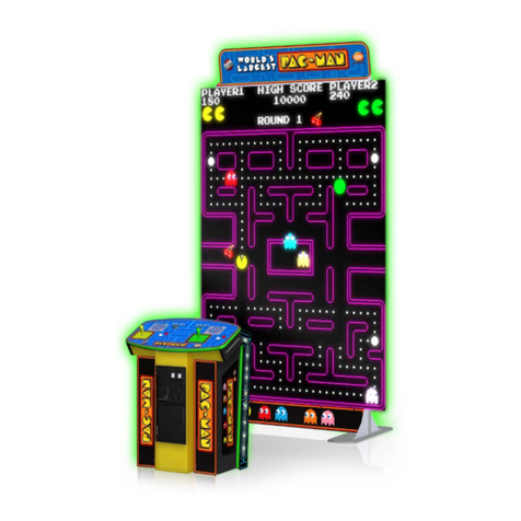
Bandai Namco World's Largest Pac-Man User manual

Bandai Namco

Bandai Namco World's Largest Pac-Man User manual

Bandai Namco PAC-MAN BATTLE ROYALE CHOMPIONSHIP DELUXE User manual

Bandai Namco

Bandai Namco PAC-MAN BATTLE ROYALE CHOMPIONSHIP DELUXE User manual

Popular Arcade Game Machine manuals by other brands

Universal Space MR.WOLF Operation manual

Universal Space

Universal Space MR.WOLF Operation manual

Universal Space COCONUT BASH Operation manual

Universal Space

Universal Space COCONUT BASH Operation manual

Bay-Tek EVOLVE installation guide

Bay-Tek

Bay-Tek EVOLVE installation guide

Global VR America's Army Operation & service manual

Global VR

Global VR America's Army Operation & service manual

Universal Space Checky Monkey Operation manual

Universal Space

Universal Space Checky Monkey Operation manual

Atronic Cashline installation manual

Atronic

Atronic Cashline installation manual

falgas CARRUSEL FIESTA user guide

falgas

falgas CARRUSEL FIESTA user guide

Konami DanceDanceRevolution Operator's manual

Konami

Konami DanceDanceRevolution Operator's manual

Bay-Tek quik drop Service manual

Bay-Tek

Bay-Tek quik drop Service manual

Adrenaline Flying Tickets Operation & service manual

Adrenaline

Adrenaline Flying Tickets Operation & service manual

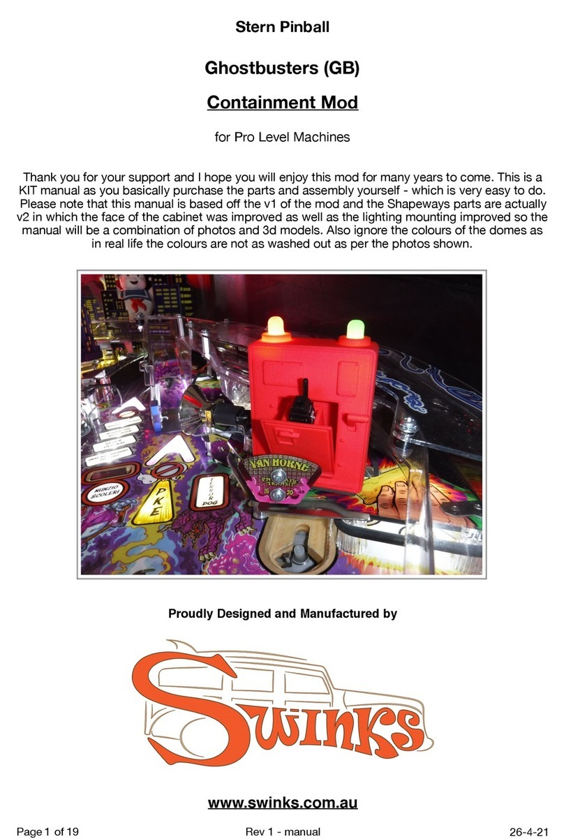
Swinks Stern Pinball Ghostbusters manual

Swinks

Swinks Stern Pinball Ghostbusters manual

Innovative Concepts in Entertainment MONOPOLY ROLL-N-GO Service manual

Innovative Concepts in Entertainment

Innovative Concepts in Entertainment MONOPOLY ROLL-N-GO Service manual

jakar SPEED CARS Operator's manual

jakar

jakar SPEED CARS Operator's manual

Carmelli HAT TRICK NG1015H Assembly instructions

Carmelli

Carmelli HAT TRICK NG1015H Assembly instructions

Bay-Tek Skee Ball 1908 Alley Service manual

Bay-Tek

Bay-Tek Skee Ball 1908 Alley Service manual

Aristocrat Technologies Mars X Upright Service manual

Aristocrat Technologies

Aristocrat Technologies Mars X Upright Service manual

NAMCO Ridge Racer V Arcade Battle Operator's manual

NAMCO

NAMCO Ridge Racer V Arcade Battle Operator's manual

Family Fun Companies Reactor Parts, Service and Distribution

Family Fun Companies

Family Fun Companies Reactor Parts, Service and Distribution

manuals.online logo
manuals.online logoBrands
  • About & Mission
  • Contact us
  • Privacy Policy
  • Terms and Conditions

Copyright 2025 Manuals.Online. All Rights Reserved.

DARK ESCAPE 4D
Operation Manual
To ensure safe operation of the machine, be sure to read this Operation Manual before use.
Keep this Operation Manual in a safe place for quick access whenever needed.
DARK ESCAPE 4D
The machine specications or the information in this Operation Manual may be changed without prior notice.
2686001101
Operation Manual
Part No.: 731-220
First edition issued September 2012
Introduction
Thank you very much for purchasing DARK ESCAPE 4D (referred to as the “machine” in this manual).
This Operation Manual describes:
How to safely install, move, transport, operate, service and dispose of the machine.
How to make full use of the machine’s functions and operate it correctly.
How to ensure the safety of players and bystanders.
Contact for this machine and machine repair inquiries
For inquiries regarding the machine or machine repairs, contact your distributor.
The copyrights, trademarks and other rights used by the machine are noted at the end of this Operation Manual.
1
Safety Precautions -Be sure to read to ensure safe operation- Test Mode Troubleshooting
1. Safety Precautions -Be sure to read to ensure safe operation-
Instructions to the Owner
If you delegate the work for installing, moving, transporting, operating, servicing or disposing the machine to
other people, ensure that these people read the relevant sections of this operation manual carefully before
starting work, and observe the corresponding precautions.
1-1 Levels of Risk
The safety and property damage precautions on the machine labels and in this Operation Manual are classied
according to their risk level, as follows.
: Failure to avoid these risks may result in serious injury or death.
: Failure to avoid these risks may result in light injury or damage to other property.
Notes about functionality that are not linked to safety are indicated with the following symbol.
: Information about product functions or protection.
1-2 Denitionof“Technician”
This Operation Manual is designed for arcade personnel. However, the sections marked “Must be performed
by a technician” in the Table of Contents are written for technicians. These tasks must be performed by
technicians only.
Technician:A person involved in design, manufacture, inspection or service at an amusement device
manufacturer, or a person involved routinely in the service or management (such as repair) or
amusement devices and who has specialist knowledge of electricity, electronics or mechanical
engineering equivalent to or higher than a technical high school graduate.
2
1. Safety Precautions -Be sure to read to ensure safe operation-
1-3 Critical Safety Precautions
Should an abnormality occur, turn off the power switch immediately to stop operations. Then,
be sure to disconnect the power cord plug from the outlet. Operating the machine while the
abnormality persists may result in a or accident.
Sections of the monitor remain at a high temperature and high voltage even after the power
switch is turned off. To avoid electric shock or burns, be careful not to accidentally touch these
sections.

Dust accumulating on the power cord plug may result in a Inspect the plug regularly and
remove any dust.
Fully insert the power cord plug into the outlet. Poor contact may generate heat and result in a
or burns.
Damage to the power cord may result in a electric shock or electrical leakage. Be sure to
observe the following.
• Keep the power cord away from heaters.
• Do not twist the power cord.
• Do not forcibly bend the power cord.
• Do not alter the power cord.
• Do not bundle the power cord.
• Do not pull the power cord. (Always unplug by holding the plug and not the power cord.)
• Do not place objects on the power cord.
• Do not allow the power cord to be caught between the machine and other devices or the
wall.
• Do not do anything else that might damage the power cord.
Do not expose the power cord and power cord plug to water. It may result in electric shock or
electrical leakage.
Do not touch the power cord plug with wet hands. It may result in electric shock.
The machine is compatible with different power supplies; 3.2 A for AC 110 V, 1.8 A for AC 230 V
and so on. To prevent and electric shock, use indoor wiring that conforms to these power
supply
Use the power supply voltage that falls ±10% of the default voltage. Using a voltage outside
this range may result in a or electric shock. However, to ensure that the machine operates
in the optimum condition, keep the default voltage as much as possible.

Use the consumables and service parts (including screws) that are by NAMCO BANDAI
Games Inc. To order parts, contact your distributor.
Do not modify the machine without permission. Do not perform any operations that are not
described in this Operation Manual. Modifying the machine may create unforeseen hazards.
When transporting and installing the machine in a different location, be sure to keep this Operation
Manual together with the machine.
3
1. Safety Precautions -Be sure to read to ensure safe operation-
Safety Precautions -Be sure to read to ensure safe operation- Test Mode Troubleshooting
1-4 Machine Warning Labels
The warning labels contain important information for ensuring safety. Be sure to observe the
following.
• To ensure that the warning labels attached to the machine are always clearly visible, install
the machine in an appropriate location with ample illumination and keep the labels clean
at all times. Also make sure that the labels are not hidden by other machines or objects.
• Do not remove or alter the warning labels.
• If a warning label becomes excessively dirty or damaged, replace it with a new one. To
order warning labels, contact your distributor.
Rear assembly
Caution sticker Capacity Limit DES (EXP)
Part No.: 461-774
Warning sticker Service (B) EXP
Part No.: 461-539
Rear caster bracket
Warning sticker Installation and Transport (EXP)
Part No.: 461-775
*The rear caster brackets are removed other than during
disassembly and transport.
4
1. Safety Precautions -Be sure to read to ensure safe operation-
Center assembly
Front assembly
Warning sticker Service (B) EXP
Part No.: 461-539
Warning sticker Service (B) EXP
Part No.: 461-539
5
Table of Contents Test Mode Troubleshooting
Table of Contents
Introduction
1. Safety Precautions -Be sure to read to ensure safe operation- ...........................................................1
1-1 Levels of Risk.................................................................................................................................. 1
1-2 Denition of “Technician”................................................................................................................. 1
1-3 Critical Safety Precautions.............................................................................................................. 2
1-4 Machine Warning Labels................................................................................................................. 3
Table of Contents....................................................................................................................5
2. Specications ...................................................................................................................10
3. Package Contents ............................................................................................................ 14
4. Overall Structure (Part Names) ........................................................................................ 22
5. Delivery and Installation Conditions .................................................................................24
5-1 Installation Conditions................................................................................................................... 24
5-1-1 Installation Locations to Avoid...............................................................................................................................24
5-1-2 Play Zone for the Installed Machine......................................................................................................................25
5-2 Required Dimensions for the Delivery Route (Such as Doors and Corridors) .............................. 26
6. Moving and Transporting.................................................................................................. 28
6-1 Moving (On the Same Floor)......................................................................................................... 28
6-2 Transporting.................................................................................................................................. 29
6-2-1 Transporting Manually (Such as Carrying on Stairs).............................................................................................29
6-2-2 Loading and Unloading to and from a Vehicle.......................................................................................................30
6-2-3 Transporting on a Vehicle......................................................................................................................................31
7. Operation..........................................................................................................................32
7-1 People Who Should Avoid Playing................................................................................................ 32
7-2 Safety Precautions for Playing...................................................................................................... 33
7-3 Important Parts for Ensuring Player and Bystander Safety .......................................................... 33
7-4 Pre-operation Inspection............................................................................................................... 34
7-4-1 Safety Inspection (Before Power On)....................................................................................................................34
7-4-2 Function Inspection (After Power On) ...................................................................................................................35
7-5 Playing the Game ......................................................................................................................... 36
(1) Basic Rules.............................................................................................................................................................36
(2) Gun Types and Features ........................................................................................................................................36
(3) Explanation of the Game System ...........................................................................................................................37
(4) START Button.........................................................................................................................................................37
(5) 2D/3D Switching Button..........................................................................................................................................37
7-6 Power Switch and Adjustment Switches....................................................................................... 38
7-6-1 Power Switch Position and Turning the Power Switch On ....................................................................................38
7-6-2 Adjustment Switches.............................................................................................................................................39
6
Table of Contents
7-7 Test Mode ..................................................................................................................................... 40
7-7-1 MENU Screen .......................................................................................................................................................40
(a) Error Display when the Rack Assembly Internal Battery has Run Out ...................................................................40
7-7-2 Game Cost and Related Settings (COIN OPTIONS) ............................................................................................42
7-7-3 Game Contents Settings (GAME OPTIONS)........................................................................................................43
7-7-4 Testing the Switches, Sensors and Other Components (I/O TEST)......................................................................45
(a) SWITCH TEST .......................................................................................................................................................46
(b) OUTPUT TEST (Cabinet Gimmick Test).................................................................................................................47
(c) GUN TEST (Crosshairs and Gun Vibration Unit Check Screen) ............................................................................48
GUN INITIALIZE (Crosshairs Adjustment Screen)..........................................................................................49
(d) VITAL SENSOR TEST (Startle Sensor Test) ..........................................................................................................51
(e) LED TEST...............................................................................................................................................................52
7-7-5 Monitor Adjustment (MONITOR TEST) .................................................................................................................53
7-7-6 Sound Adjustment (SOUND TEST).......................................................................................................................55
7-7-7 Displaying and Initializing Game Data (BOOKKEEPING).....................................................................................56
7-7-8 Other Options (OTHERS)......................................................................................................................................57
(a) Stereoscopic Display Setting (3D VIEW SETTING) ...............................................................................................58
(b) Internal Clock Setting (CLOCK SETTING) .............................................................................................................59
(c) HDD CHECK ..........................................................................................................................................................60
(d) Initializing the Backup Memory (BACKUP MEMORY INITIALIZE).........................................................................61
7-7-9 Software Update (SOFTWARE UPDATE).............................................................................................................62
7-8 Error Display (For Operators) ....................................................................................................... 63
7-8-1 Game Play Using Service Credits.........................................................................................................................63
7-9 Gun Assembly Adjustment (Initialization) after Parts Replacement.............................................. 64
7-9-1 Initializing the Gun Assembly Volume ...................................................................................................................64
7-10 Cleaning........................................................................................................................................ 65
7-10-1 Cleaning the 3D Glasses.......................................................................................................................................65
7-10-2 Cleaning the 3D Glasses Cases ...........................................................................................................................65
7-10-3 Cleaning the Monitor Panel...................................................................................................................................65
7
Table of Contents
Table of Contents Test Mode Troubleshooting
8. Technician’s Manual - Must be performed by a technician -..............................................................66
8A. Installation and Assembly...............................................................................................66
8A-1 Required Tools .............................................................................................................................. 66
8A-2 Number of Workers and Work Time.............................................................................................. 66
8A-2-1 Number of Workers ...............................................................................................................................................66
8A-2-2 Work Time .............................................................................................................................................................66
8A-3 Securing Work Space ................................................................................................................... 67
8A-4 Assembly ...................................................................................................................................... 68
8A-4-1 Connecting the Front Assembly and Center Assembly .........................................................................................68
8A-4-2 Attaching the 3D Glasses and Glasses Cleaning Cloths ......................................................................................71
8A-4-3 Installing the Wall Assemblies ...............................................................................................................................74
8A-4-4 Connecting the Center Assembly and Rear Assembly..........................................................................................78
8A-4-5 Installing the Signboard Box Assembly .................................................................................................................80
8A-4-6 Installing the Corner Covers (L) and (R) ...............................................................................................................83
8A-4-7 Installing the Top Cover Center and Top Cover Sides (L) and (R) ........................................................................84
8A-4-8 Installing the Ceiling Tarpaulin and Side Curtains .................................................................................................87
8A-4-9 Level Adjuster Adjustment.....................................................................................................................................90
8A-5 Inserting the USB Dongle ............................................................................................................. 91
8A-6
Connecting the Communication Cables
.................................................................................................... 92
(1) Connection Method ................................................................................................................................................92
8A-7 Connecting the Power Cord and Ground...................................................................................... 93
8A-7-1 Connecting the Power Cord to the Cord Box ........................................................................................................93
8A-7-2 Connecting the Power Cord to the Outlet..............................................................................................................94
(1) In case of a 3P outlet..............................................................................................................................................94
8A-8 Power Switch Position and Turning the Power Switch On............................................................ 95
8A-8-1 Turning the Power Switch On................................................................................................................................95
8A-9 Checks after Installation................................................................................................................ 96
8B. Service ........................................................................................................................... 97
8B-1 Inspection and Service.................................................................................................................. 97
8B-1-1 Inspection Items ....................................................................................................................................................97
(1) Level Adjuster Inspection........................................................................................................................................97
(2) Power Cord Plug Inspection ...................................................................................................................................97
(3) Screw Looseness Inspection..................................................................................................................................97
(4) Communication Cable Inspection...........................................................................................................................97
(5) Game PC Board Inspection....................................................................................................................................97
8B-2 Troubleshooting ............................................................................................................................ 98
8B-2-1 Overall...................................................................................................................................................................98
8B-2-2 Front Assembly......................................................................................................................................................99
8B-2-3 Center Assembly ...................................................................................................................................................99
8B-2-4 Gun Assembly .....................................................................................................................................................100
8B-2-5 Rear Assembly ....................................................................................................................................................101
8B-2-6 Signboard Box Assembly ....................................................................................................................................101
8B-3 Error Display (For Technicians)................................................................................................... 102
8
Table of Contents
8B-4 Removing, Installing and Replacing Assemblies and Parts........................................................ 104
8B-4-1 Front Assembly....................................................................................................................................................104
(1) Replacing the Rack Assembly ..............................................................................................................................104
(2) Replacing the Switching Regulator.......................................................................................................................106
(3) Replacing the MCD AMP PC Board .....................................................................................................................108
(4) Replacing the STRAIGHT PC Board....................................................................................................................109
(5) Replacing the AIR CAN PC Board........................................................................................................................ 111
(6) Replacing the Air Cannon Speaker.......................................................................................................................113
(7) Replacing the LCD Monitor...................................................................................................................................114
8B-4-2 Center Assembly .................................................................................................................................................116
(1) Replacing the USIO (T) PC Board........................................................................................................................116
(2) Replacing the GUN DRIVE PC Board ..................................................................................................................118
(3) Replacing the Illuminated Switch and LED Lamp of the 2D/3D Switching Button................................................119
8B-4-3 Gun Assembly .....................................................................................................................................................121
(1) Removing and Installing the Gun Assembly .........................................................................................................121
(2) Replacing the Variable Registor (for Right/Left) ...................................................................................................122
(3) Replacing the Variable Registor (for Up/Down)....................................................................................................125
(4) Replacing the Micro Switch ..................................................................................................................................127
(5) Replacing the Trigger and Spring .........................................................................................................................128
(6) Replacing the Illuminated Switch and LED Lamp of the START Button...............................................................129
(7) Replacing the Vibration Unit .................................................................................................................................131
(8) Replacing the Gun Harness 2...............................................................................................................................133
(9) Replacing the Gun Harness 5...............................................................................................................................135
(10) Replacing the VSS Module...................................................................................................................................136
8B-4-4 Rear Assembly ....................................................................................................................................................138
(1) Replacing the Switching Regulator.......................................................................................................................138
(2) Replacing the LAM DRIVE PC Board...................................................................................................................140
(3) Replacing the Speed Control Driver .....................................................................................................................141
(4) Replacing the MOTOR IF PC Board.....................................................................................................................142
(5) Replacing the DC Brushless Motor and Rotor Cover ...........................................................................................143
(6) Replacing the Rear Seat Cushion ........................................................................................................................148
(7) Replacing LED Modules .......................................................................................................................................150
Replacing a LED module inside the rear sign panel. ....................................................................................150
Replacing the LED module at the front of the top cover center.....................................................................154
(8) Replacing the 3D Glasses ....................................................................................................................................156
(9) Replacing the Glasses Cleaning Cloth .................................................................................................................157
8B-4-5 Signboard Box Assembly ...................................................................................................................................158
(1) Replacing LED Modules .......................................................................................................................................158
8B-4-6 Wall Assembly .....................................................................................................................................................160
(1) Replacing LED Modules .......................................................................................................................................160
8B-5 LCD Monitor Adjustment ............................................................................................................. 162
8B-5-1 Removing and Installing the Monitor Adjustment Switches.................................................................................162
8B-5-2 LCD Monitor Picture Quality Adjustment.............................................................................................................164
8B-5-3 LCD Monitor Settings ..........................................................................................................................................165
9. Disposal .........................................................................................................................166