Bartec 07-4230 Series Quick start guide

Operational Instruction
(Translation)
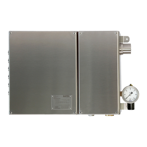
Ex d Control Station
Type 07-4230-..../...
BARTEC
GmbH Max-Eyth-Straße 16
97980 Ba Mergentheim
Germany
Tel.: +49 7931 597-0
Fax: +49 7931 597-119
info@bartec. e
www.bartec. e
Reservation Technical ata subject to change without notice. Changes, errors an
misprints may not be use as a basis for any claim for amages.
EN 1/5
Explosion protection
Technical data
Maximum Ex protection type
Depen ing on the installe components; ob-
serve the specifications on the type label.
ATEX
Ex protection type
II 2G
Ex b eb ia/ib [ib]
IIA, IIB resp. IIC T6, T5 resp. T4
II 2(1)G
Ex b eb ia/ib [ia]
IIA, IIB resp. IIC T6, T5 resp. T4
CE 0044
Certi ication
Ex control station: PTB 03 ATEX 1138
Empty closure: PTB 03 ATEX 1137 U
IECEx
Ex protection type
Ex b eb ia/ib [ia] IIA, IIB resp. IIC T6,
T5 resp. T4
Ex b eb ia/ib [ib] IIA, IIB resp. IIC T6,
T5 resp. T4
Certi ication
Ex control station: IECEx PTB 11.0038
Empty closure: IECEx PTB 11.0026U
Ambient temperature
Depen ing on the installe parts; observe
specifications on the type label.
-20 °C to +55 °C
(-4 °F to +131 °F)
Approved or zones
1 an 2
Components
Only Ex-certifie components may be in-
stalle in the junction box.
Follow the components manufacturer’s
mounting irections an safety instructions.
Other applicable documents
–
Circuit iagram
–
Mounting instructions/operating instruc-
tions for the installe components
–
Delivery note
The retention of these ocuments is man a-
tory.
Electrical data
Rate voltage: up to 690 V
Power issipation: max. 67 W
Protection class
IP 54 (IEC 60529)
Rated cross-section o conductor
Max. 16 mm
2
Weight
Approx. 4 kg (8.82 lb)
Mechanical strength
Impact energy max. 7 Nm
Enclosure material
Aluminium
Lid closure
Cheesehea screws,
ISO 4762-M8 x 25-A2-70 or A4-70
Dimensions
See page 4.
01
-4230-7D0001/C-12/12-STVT-294265
Note on instructions
When working in hazar ous areas, the safety of
personnel an equipment epen s on com-
pliance with the
relevant safety regulations. The
people in charge of installation an mainten-
ance bear a special responsibility. It is essential
that they have an exact knowle ge of the
applicable rules an regulations.
The instructions provi e a summary of the most
impor
tant safety measures an must be rea by
everyone working with the pro uct so that they
will be familiar with the correct han ling of the
pro uct.
The instructions have to be kept for future
reference an must be available throughout the
expecte life of the pro uct.
Description
These Ex control stations
are use wherever
electrical components are nee e in potentially
explosive environments in z
one 1 (certifie
hazar sub-
groups IIA, IIB, IIC, temperature
classes T4, T5, T6). Electrical operating equip-
ment, such as contactors, relays an controls
are fitte as require .
Electrical connections can be establishe either
with a flange -on junction box
with “Ex e“ type
of protection or irectly with cables an cable
entries that are approve for the hazar o
us
area.
If the evices contain intrinsically safe circuits or
Ex i components, the electrical limits that are
ecisive for “intrinsic safety” (see accompanying
ocuments) must be a here to.

Operational Instruction
(Translation)
Ex d Control Station
Type 07-4230-..../...
BARTEC
GmbH Max-Eyth-Straße 16
97980 Ba Mergentheim
Germany
Tel.: +49 7931 597-0
Fax: +49 7931 597-119
info@bartec. e
www.bartec. e
Reservation Technical ata subject to change without notice. Changes, errors an
misprints may not be use as a basis for any claim for amages.
EN 2/5
01
-4230-7D0001/C-12/12-STVT-294265
Sa ety Instructions
The Ex control station
may be use only
within the specifie temperature class an the
temperature range in icate for it (see type
label).
The Ex control station
is not suitable for use
in Zone 0. The Ex control station
may be
operate only if it is clean an not amage in
any way.
Utiliz
ation in areas other than those specifie
an the mo ifications of the pro uct by anyone
other than the manufa
cturer are not permitte
an will exempt BARTEC from liability for
efects an any further liability.
The generally applicable statutory rules an
other bin ing irectives relating to workplace
safety, acci ent prevention an environmental
protection must be observe .
When using electrical systems, the relevant
regulations on installation an operation must
be complie with. The specifications on the
type label must be observe .
Observe the applicable laws an irectives
when commissioning or restarting ope
ration.
Always follow the safety instructions on the
operating equipment.
Marking
Particularly important points in these instruc-
tions are marke with a symbol:
DANGER in icates a hazar ous situation
which, if not avoi e , will result in eath
or
serious injury.
WARNING in icates a hazar ous
situation
which, if not avoi e , coul
result in eath or
serious injury.
CAUTION in icates a hazar ous situation
which, if not avoi e , coul result in minor
or
mo erate injury.
NOTICE is use to a ress practices not
relate to personal injury.
Note
Important instructions and information on
effective, economical and environmentally
compatible handling.
Standards con ormed to
EN 60079-0:2009
EN 60079-1:2007
EN 60079-7:2007
EN 60079-11:2007
as well as
EN 60439-2:2000 + A1:2005
EN 62208:2003
EN 60445:2010
EN 60529:1991 + A1:2000
Note
For the standards for the installed parts, see
the separate documentation for the built-
in
component.
Assembly / Disassembly
Death or serious injury due to incorrect
assembly.
Metallic enclosures in hazar ous areas
require equipotential bon ing with at least
4
mm². The connections must be secure
against self loosening.
Risk o injury due to incorrect proceedings.
Only authoriz
e an qualifie personnel
who are authorize an traine to assem-
ble electrical components in hazar ous
(potentially explosive) areas
may o any of
the assembly, isassembly, installation an
commissioning work.
The relevant installation an operating
regulations must be observe when
setting
up or operating explosion-
proof electric
systems.
Always isconnect the Ex control station
from voltage before assembling / isas-
sembling.
Follow the components mounting instructi-
ons/operating instructions.
Check when assembling:
•Mount the Ex control station with resis-
tance to torsion on an even supporting
surface.
Fixing imensions an the holes
to be ma e, see rawings on page 4.
•
Secure the connections against self
loosening.
Note
For enclosures set up outdoors it may be
necessary to imp
lement measures to ensure
operation in accordance with the intended
purpose (e.g. shelter from the rain or an outer
enclosure with a suitable protection class).
Death or serious injury due to a potentially
explosive atmosphere.
Never open the Ex control station
in the
presence of a potentially explosive atmos-
phere.
Always isconnect the Ex control station
from voltage before opening it.
Pay attention at the opening/closing of flame-
proof enclosures:
•Disconnect the Ex control station
from
voltage.
•
Loosen the screws in the cover cam until
they are no longer engage with the
threa s.
•
Unscrew the li to the left an make sure
it can’t fall off.
•Close the en
closure again in reverse
or er.
Installation
Death or serious injury due to improper use.
Extensions or mo ifications to the
Ex
control station
are only permissible if the
manufacturer’s approval is obtaine first.
The IEC/EN60079-14 must be observe .
Check when installing:
•
When connecting cables an con uctors
to operating equipment with
the “Ex e”
type of protection, use Ex-
certifie cable
entries that are suitable for the respective
types of cables an con uctors. They
must conform to the “Ex e” type of protec-
tion an have a suitable sealing element
to maintain the control station’s prot
ection
class.
•
Connect metallic cable entries to the
earthing system.
•Seal unuse cable entry holes with Ex-
certifie stopping plugs.
•When connecting irectly to the flame-
proof enclosure, use Ex-
certifie entries
that are suitable for the enclosure capaci-
ty, the gas sub-group an the con uctor.
Take care when connecting con uctors:
•
Always use suitable crimping tools when
crimping the wire-
en ferrules to ensure a
consistent quality of pressing each time.
•Take care
to establish the connection
properly.
•Tighten a
ll terminal points (inclu ing those
not in use) securely.

Operational Instruction
(Translation)
Ex d Control Station
Type 07-4230-..../...
BARTEC
GmbH Max-Eyth-Straße 16
97980 Ba Mergentheim
Germany
Tel.: +49 7931 597-0
Fax: +49 7931 597-119
info@bartec. e
www.bartec. e
Reservation Technical ata subject to change without notice. Changes, errors an
misprints may not be use as a basis for any claim for amages.
EN 3/5
01
-4230-7D0001/C-12/12-STVT-294265
Commissioning
Before commissioning, check that:
•The evice has been installe in compli-
ance with regulations.
•The enclosure is not amage .
•T
he connection has been establishe
properly.
•The cables have been lai correctly.
•All screws have been tightene securely.
•The evice functions perfectly.
Transport, Storage
Damage to the Ex d control station through
incorrect transport or incorrect storage.
Transport an storage is permissible in
original packaging only.
Operation
Death or serious injury through improper
use.
The Ex control station
may be operate
only within the technical limits that apply to
it (see page 1).
Maintenance and Fault Clearance
Death or serious injury through damaged
lameproo encapsulation.
The threa e gaps must be protecte .
They must not be machine or varnish
e
at any time later.
Defective parts in the flameproof encapsu-
lation must be replace with original parts
imme iately.
Risk o injury due to incorrect proceedings.
Only authoriz
e qualifie personnel are
allowe to o any of the work relating to
maintenance an fault clearance.
IEC/EN 60079-17 must be observe .
Maintenance work
The operator of the Ex control station
must
keep it in goo con ition, operate it correctly,
monitor it, an clean it regularly.
•Visually inspect the threa e gap.
•Visually inspect the flameproof encapsu-
lation for amage.
•Check sealings for effectiveness.
•
Replace ol or amage sealings with
new original seals.
•
Check that the connection terminals,
cable & con uctor entries are secure.
Note
In the course of maintenance particular atten-
tion must be paid to checking that the parts
essential for the type of protection and proper
functioning are in good condition.
Fault Clearance
The Ex control station i
s efective if the
flameproof encapsulation
is amage an /or if
one of the compo
nents oes not function any
longer.
In this case:
•Imme iately replace the
efective parts in
the flameproof encapsulation
with original
parts.
•Replace or repair the efective compo-
nents with original parts.
Note
Follow the components mounting instructi-
ons/operating instructions to replace or repair
the components.
Accessories,
S
pare
P
arts
See BARTEC catalogue.
Disposal
The components in the Ex control station
contain metal an plastic parts.
Therefore the statutory requirements for ispos-
ing of electronic scrap must be observe (e.g.
isposal by an approve isposal company).
Service Address
BARTEC GmbH
Max-Eyth-Straße 16
97980 Ba Mergentheim
Germany
Tel.: +49 7931 597-0
Fax: +49 7931 597-119

Operational Instruction
(Translation)
Ex d Control Station
Type 07-4230-..../...
BARTEC
GmbH Max-Eyth-Straße 16
97980 Ba Mergentheim
Germany
Tel.: +49 7931 597-0
Fax: +49 7931 597-119
info@bartec. e
www.bartec. e
Reservation Technical ata subject to change without notice. Changes, errors an
misprints may not be use as a basis for any claim for amages.
EN 4/5
01
-4230-7D0001/C-12/12-STVT-294265
Dimensions
in mm (in)
Ex d aluminium enclosure Lid closed I
Lid with inspection window Ø 80 mm (3.15”) II

Operational Instruction
(Translation)
Ex d Control Station
Type 07-4230-..../...
BARTEC
GmbH Max-Eyth-Straße 16
97980 Ba Mergentheim
Germany
Tel.: +49 7931 597-0
Fax: +49 7931 597-119
info@bartec. e
www.bartec. e
Reservation Technical ata subject to change without notice. Changes, errors an
misprints may not be use as a basis for any claim for amages.
EN 5/5
01
-4230-7D0001/C-12/12-STVT-294265
Table of contents
Other Bartec Control Unit manuals

Bartec
Bartec 07-3323-3 Series User manual

Bartec
Bartec RFID Snap-on Module User manual

Bartec
Bartec VOLUTANK Petro 3003 User manual

Bartec
Bartec 07-61.1 Series Quick start guide

Bartec
Bartec 17-A1Z0-0005 User manual

Bartec
Bartec POLARIS SMART HMI 17-71V6-1 Series User manual

Bartec
Bartec APEXmpc Instruction Manual

Bartec
Bartec APEXmv 07-37A2-2211 730 Series User manual

Bartec
Bartec APEXpy 07-37A2-2111/ 520Series User manual

Bartec
Bartec 17-A1Z0-0005 User manual