1
MINI FLY
2
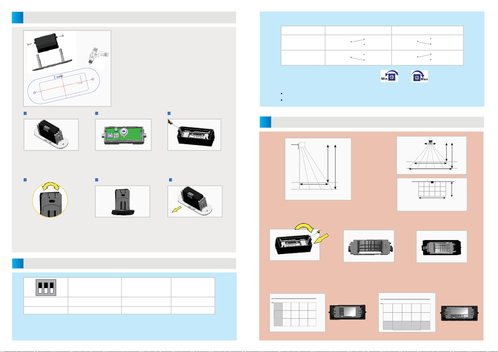
Remove the aluminum screws on
each side of MFCA bracket with
screwdriver.
Open the front cover, setting and chec-
king the position of dip-switch and poten-
tiometer (take dip-switch&potentiometer
setting for reference.)
Install the masking lens if needed,
and get related detection field(
take detection field setting for
reference.)
Connecting the cable, and fix the sen-
sor to MFCA base with 2 black screws
, notice the mounting direction, and
make sure the position of wire connec-
tor is facing outside the door(MFCA).
Step 1. Step 2. Step 3.
Step 4. Step 6.Step 5.
Dip-switch 1 Dip-switch 2 Dip-switch 3
on Strong interference mode Passive output(NC) Hold time:2s
off Factory mode Active output(NO) Hold time:0.5s
54
Working model setting ( Dip-switch 1)
Factory mode: Suit for normal working environment (factory setting).
Strong interference mode: Suit for complex environment with lots of interference source ( this will increase the response time about 10%.)
Stick the template on the ceiling and cut out the hole.
Clip the sensor on the MFCA with screws. If needed
to change the factory settings, please follow up the
following steps (step1-step6):
Protect the sensor periphery before sawing
Mounting template
Ceiling aperture
Þ[ Þ[
The sensor must be firmly fastened in order to avoiad vibrations.
Mounting tips:
When mounting the MINI FLY, make sure you adjusting the angle
before tightening the screws.
Always use the aluminum screws to fasten the internal bracket
and the black screws to fix the sensor.
After changing the parameter,
close the front cover, installed the
bracket, and tighten two screws on
each side of the bracket after adjust
the angle .
"+" stands for the detection field
towards person. MFCA maximum angle
is +4°.
"-" stands for the detection field
towards doors. MFCA maximum angle
is -4°.
MOUNTING & SETTING
DIP-SWITCH SETTING
Outside the door
MINI FLY
3
The above drawings show the typical sensing field dimensions.
You can move the sensor’s detcion field through change the angle of MFCA bracket ( -4° to +4°) .
Relay configurations Active mode Passive mode
DETECTION
NO DETECTION
Relay model setting (Dip-switch 2)
Adjustment the sensitivity with potentiometer
LED:
Profile view
Flat view
Front view
COM (3)
COM (3)
COM (3)
COM (3)
NO (4)
NO (4)
NO (4)
NO (4)
NC (5)
NC (5)NC (5)
NC (5)
P P
FP FP FP
P'HSWK
PP
PP
P P
FP FP FP FP FP
P
P
P
P +HLJKWP
*UUXZNXKYNURJ
When sensor is power on , it flash10 seconds.
Position the screwdriver as shown to
remove the masking lens.
To adjust the sensing field , use
the masking lens. To tailor the
sensing field, cut the segments.
Use the guide pins to insert the
masking lens on the front cover.
IS
*UUXZNXKYNURJ
Sensing field examples:
*UUXZNXKYNURJ
IS
Sensing field
No detection field
Sensing field
No detection
field
DETECTION FIELD SETTING
When sensor detecting movement, LED light up.


